
50
DC to 2000 MHz
Monolithic Amplifiers
Drop-In
MAR+ SERIES
CASE STYLE: VV105
Features
Electrical Specifications *
REV. OR
M107249
MAR+ SERIES
060905
Page 1 of 2
∑ wideband, DC to 2000 MHz
∑ high gain, up to 32.5 dB @ 100 MHz
∑ low noise
∑ MAR-1+, MAR-3+, MAR-4+ are equivalent to MSA-0185,
MSA-0385, MSA-0485, respectively.
∑ cascadable
∑ protected by US Patent, 6,943,629 (except MAR-6+)
MODEL
NO.
FREQ.
2
(MHz)
GAIN (dB)
Typical at MHz
MAXIMUM
POWER
(dBm)
DYNAMIC
RANGE
VSWR
(:1)
Typ.
ABSOLUTE
MAXIMUM
RATING
6
(25∫C)
DC
OPERATING
POWER
7
at Pin 3
THERMAL
RESISTANCE
5
PRICE
$
f
L
f
U
100
1000
2000
Note
1
Min.
Output
(1 dB
Compr.)
Typ.
Input
(no dam-
age)
NF
(dB)
Typ.
IP3
(dBm)
Typ.
In
Out
I
(mA)
P
(mW)
Cur-
rent
(mA)
Device
Volt
Typ.
∫C/W
Qty.
(30)
MAR-1
+
DC
1000
17.8
16.5
--
15
+2.5
+13
3.5
+14.0
1.3
1.2
40
200
17
5.0
115
0.99
MAR-3
+
DC
2000
12.5
12.0
10.5
8.0
+10.0
+13
6.0
+23.0
1.5
1.7
70
400
35
5.0
115
1.19
MAR-4
+
DC
1000
8.3
8.0
--
7.0
+12.5
+13
7.0
+25.5
1.5
1.9
85
500
50
5.25
100
1.29
MAR-6
+
DC
2000
22
20
17
15
+3.0
+13
3.0
+14.5
1.7
1.7
50
200
16
3.50
120
1.16
Applications
∑ cellular
∑ PCN instrumentation
NOTES:
1. Minimum gain over the full frequency range and temperature range.
2. Low frequency cutoff determined by external coupling capacitors.
3. Frequency at which output power, NF and IP3 are specified: 500 MHz for MAR-1+ and MAR-6+,
1000 MHz for all other models.
4. MAR-6+ models potentially unstable with very high VSWR terminations.
5. Thermal resistance jc is from hottest junction in device to mounting surface of leads.
6. Permanent damage may occur if any of these limits are exceeded. These ratings are not intended for continuous
normal operation.
7. Supply voltage must be connected to pin 3 through a bias resistor in order to prevent damage. See "Biasing MMIC Am
plifiers" in minicircuits.com/application.html. Reliability predictions are applicable at specified current & normal
operating conditions.
Maximum Ratings
Operating Temperature
-40∞C to 85∞C
Storage Temperature
-55∞C to 100∞C
Pin Connections
RF IN
1
RF OUT
3
DC
3
GROUND
2,4
Model Identification
Model No.
Marking
MAR-1+
A01
MAR-3+
A03
MAR-4+
A04
MAR-6+
A06
INTERNET
http://www.minicircuits.com
P.O. Box 350166, Brooklyn, New York 11235-0003 (718) 934-4500 Fax (718) 332-4661
Distribution Centers NORTH AMERICA 800-654-7949 ∑ 417-335-5935 ∑ Fax 417-335-5945 ∑ EUROPE 44-1252-832600 ∑ Fax 44-1252-837010
Mini-Circuits
Æ
Mini-Circuits ISO 9001 & ISO 14001 Certified
MTTF vs. Junction Temp.
0
1
10
100
1,000
10,000
100,000
1,000,000
80 90 100 110 120 130 140 150 160 170 180 190 200 210
Junction Temperature (∞ C)
M
T
T
F
(
Y
e
a
r
s
)
MAR-1+,-3+,-4+
MTTF vs. Junction Temp
1
10
100
1,000
10,000
100,000
Junction Temperature (∞C)
M
T
T
F
(
Y
e
a
r
s
)
80 100 120 140 160 180 200
MAR-6+
Prefix letter (optional) designates assembly location
+ RoHS compliant in accordance
with EU Directive (2002/95/EC)
The +Suffix has been added in order to identify RoHS
Compliance. See our web site for RoHS Compliance
methodologies and qualifications.
* Test data based on models tested with bent leads per case style WW107
A
B
C
D
E
F
G
wt
.085
.060
.008
.020
.250
.012
.025 grams
2.16
1.52
0.20
0.51
6.35
0.30
0.64
.015
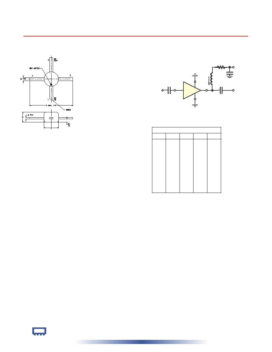
Outline Dimensions ( )
inch
mm
Outline Drawing
Page 2 of 2
MAR+ SERIES
INTERNET
http://www.minicircuits.com
P.O. Box 350166, Brooklyn, New York 11235-0003 (718) 934-4500 Fax (718) 332-4661
Distribution Centers NORTH AMERICA 800-654-7949 ∑ 417-335-5935 ∑ Fax 417-335-5945 ∑ EUROPE 44-1252-832600 ∑ Fax 44-1252-837010
Mini-Circuits
Æ
Mini-Circuits ISO 9001 & ISO 14001 Certified
4
2
3
1
Cblock
IN
Cblock
Ibias
OUT
Vd
RFC (Optional)
Cbypass
Vcc
Rbias (Required)
Typical Biasing Configuration
Resistor Values ("1%" Res.)
Vcc
MAR-1+ MAR-3+ MAR-4+ MAR-6+
7
118
57.6
34.8
215
8
178
86.6
54.9
280
9
237
115
75
340
10
294
143
95.3
402
11
357
169
115
464
12
412
200
133
536
13
464
226
154
590
14
536
255
174
665
15
590
287
196
715