INTERNET
http://www.minicircuits.com
P.O. Box 350166, Brooklyn, New York 11235-0003 (718) 934-4500 Fax (718) 332-4661
Distribution Centers NORTH AMERICA 800-654-7949 ∑ 417-335-5935 ∑ Fax 417-335-5945 ∑ EUROPE 44-1252-832600 ∑ Fax 44-1252-837010
Mini-Circuits
Æ
Mini-Circuits ISO 9001 & ISO 14001 Certified
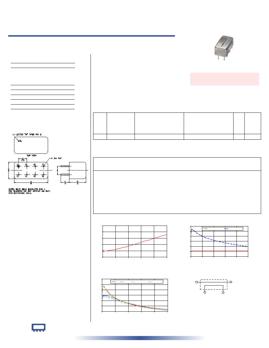
50 1 to 400 MHz
Bi-Directional Coupler
Plug-In
CASE STYLE: A01
PRICE: $13.70 ea. QTY. (1-9)
Outline Dimensions ( )
inch
mm
Maximum Ratings
Pin Connections
Outline Drawing
Directional Coupler Electrical Specifications
REV. A
M98898
PDC-10-1BD
WZ/TD/CP
060724
A
B
C
D
E
F
.770
.800
.385
.400
.370
.400
19.56 20.32
9.78 10.16
9.40 10.16
G
H
J
K
wt
.200
.20
.14
.031
grams
5.08
5.08
3.56
0.79
5.2
Typical Performance Data
PDC-10-1BD+
PDC-10-1BD
Operating Temperature
-55∞C to 100∞C
Storage Temperature
-55∞C to 100∞C
Features
∑ wideband, 1 to 400 MHz
∑ up to 4W power input
∑ excellent directivity, 35 dB typ.
∑ low insertion loss, 0.8 dB typ.
∑ rugged welded construction, hermetically sealed
Applications
∑ VHF/UHF
∑ communication receivers & transmmitters
∑ instrumentation
PDC-10-1BD
MAINLINE LOSS
0.4
0.6
0.8
1.0
1.2
1.4
0
80
160
240
320
400
FREQUENCY (MHz)
MAINLINE
LOSS
(dB)
at RF level of -10 dBm
PDC-10-1BD
COUPLING & DIRECTIVITY
0
10
20
30
40
50
60
0
80
160
240
320
400
FREQUENCY (MHz)
COUPLING
&
DIRECTIVITY
(dB)
IN-CPL FWD
IN-CPL-REV
at RF level of -10 dBm
PDC-10-1BD
RETURN LOSS
10
15
20
25
30
35
40
0
80
160
240
320
400
FREQUENCY (MHz)
R
E
T
U
R
N
L
O
S
S
(
d
B
)
IN
OUT
CPL FWD
CPL REV
at RF level of -10 dBm
electrical schematic
CPL
FORWARD
CPL
REVERSE
IN
OUT
INPUT
1
OUTPUT
4
COUPLED (forward)
3
COUPLED (reverse)
6
GROUND
2,5,7,8
CASE GROUND
2,5,7,8
+ RoHS compliant in accordance
with EU Directive (2002/95/EC)
The +Suffix identifies RoHS Compliance. See our web site
for RoHS Compliance methodologies and qualifications.
Frequency
(MHz)
Mainline Loss
(dB)
Coupling
(dB)
Directivity
(dB)
Return Loss
(dB)
In-Out
In-Cpl Fwd
Out-Cpl Rev Out-Cpl Fwd
In-Cpl Rev
In
Out
Cpl Fwd
Cpl Rev
1.00
0.63
11.50
11.50
81.10
45.13
28.35 22.22
22.43
29.02
5.50
0.57
11.47
11.45
46.78
52.71
33.44 24.48
24.09
33.36
10.00
0.60
11.49
11.48
41.73
53.31
33.34 24.67
24.02
32.94
20.00
0.60
11.49
11.48
37.25
51.62
31.02 24.71
23.55
31.09
40.00
0.61
11.51
11.48
34.59
47.08
26.87 24.06
22.62
27.54
80.00
0.65
11.55
11.54
32.34
40.59
22.30 21.81
20.63
22.68
160.00
0.75
11.63
11.67
27.76
32.42
17.43 17.71
16.91
17.30
240.00
0.87
11.70
11.84
23.89
27.12
14.58 14.90
14.36
14.21
320.00
1.00
11.74
12.05
20.01
23.15
12.81 13.06
12.71
12.19
400.00
1.12
11.74
12.27
17.04
19.89
11.60 11.78
11.62
10.87
FREQ.
(MHz)
COUPLING
(dB)
MAINLINE LOSS
1
(dB)
DIRECTIVITY
(dB)
VSWR
(:1)
POWER
INPUT, W
Nom. Flatness
L
M
U
L
M
U
L
MU
f
L
-f
U
Typ. Max. Typ. Max. Typ. Max. Typ. Min. Typ. Min. Typ. Min.
Typ.
Max. Max.
1-400
11.5±0.5
±0.5
0.6
0.9
0.8
1.1
0.9
1.3
55
35
35
20
22
15
1.2
2.0
4.0
L = low range [f
L
to 10 f
L
] M = mid range [10 f
L
to f
U
/2] U= upper range [f
U
/2 to f
U
]
1. Mainline loss includes theoretical power loss at coupled port.