2 Way-0∞ 50
3700 to 4200 MHz
Power Splitter/Combiner
Ultra-Small Ceramic
CASE STYLE: FV1206-1
PRICE: $ 2.50 ea. QTY (10-49)
$ 0.99 ea. QTY (100)
SCN-2-45
INSERTION LOSS
3.0
3.2
3.4
3.6
3.8
4.0
3700
3800
3900
4000
4100
4200
FREQUENCY(MHz)
I
N
SERTI
O
N
LO
SS (
d
B)
S-1(dB)
S-2 (dB)
SCN-2-45
ISOLATION
0
5
10
15
20
25
30
3700
3800
3900
4000
4100
4200
FREQUENCY (MHz)
IS
OL
A
T
ION
(d
B
)
SCN-2-45
RETURN LOSS
0
5
10
15
20
25
30
35
3700
3800
3900
4000
4100
4200
FREQUENCY (MHz)
RETURN LO
SS (
d
B)
S-RETURN LOSS
1-RETURN LOSS
2-RETURN LOSS
Typical Performance Data
Frequency
(MHz)
Insertion Loss
(dB)
S-1
Amplitude
Unbalance
(dB)
Isolation
(dB)
(dB)
S-2
Phase
Unbalance
(deg.)
Maximum Ratings
Pin Connections
Features
SUM PORT
2
PORT 1
6
PORT 2
4
GROUND
1,3,5
PORT 1-2
resistor external 100 OHMS
Applications
Operating Temperature
-55∞C to 100∞C
Storage Temperature
-55∞C to 100∞C
Power Input (as a splitter)
4W* max.
Splitter Electrical Specifi cations
REV. A
M98898
SCN-2-45
ED-11378C/2
AD/TD/CP
051107
∑ isolation resistor, external 100 ohms
∑ low insertion loss, 0.7 dB typ.
∑ excellent amplitude unbalance, 0.2 dB typ.
∑ excellent phase unbalance, 1.5 deg. typ.
∑ high isolation, 22 dB typ.
∑ excellent power handling, 4W as splitter
∑ small size, 0.12"X0.06"X0.035"
∑ ESD non-sensitive
∑ temperature stable LTCC technology
∑ wrap around terminations for excellent solderability
∑ low cost
∑ patent pending
∑ maritime mobile
Typ. Max.
PHASE
UNBALANCE
(Degrees)
INSERTION LOSS
(dB)
ABOVE 3.0 dB
AMPLITUDE
UNBALANCE
(dB)
MODEL
NO.
FREQUENCY
(MHz)
RETURN LOSS
(dB)
ISOLATION
(dB)
Typ. Min.
Typ. Max.
Typ. Max.
INPUT
Typ.
OUTPUT
Typ.
*derate linearly to 1.3W at 100∞C ambient, power input as
combiner is limited by rating of extemal 100
resistor.
3700.00
3.55
3.37
0.18
16.04
1.57
17.81
22.02
28.10
3720.00
3.55
3.38
0.17
16.28
1.65
18.21
21.85
27.94
3740.00
3.54
3.39
0.15
16.49
1.66
18.58
21.83
27.36
3760.00
3.53
3.40
0.13
16.69
1.60
18.81
21.77
27.02
3780.00
3.53
3.41
0.12
16.91
1.46
18.96
21.52
26.95
3800.00
3.53
3.41
0.12
17.16
1.31
19.12
21.17
26.69
3864.00
3.54
3.38
0.16
17.92
1.09
19.67
20.59
25.75
3896.00
3.54
3.36
0.18
18.33
1.16
20.06
20.04
24.89
3960.00
3.54
3.34
0.19
19.05
1.26
20.35
19.56
23.33
4016.00
3.54
3.35
0.19
19.83
1.35
20.24
19.39
22.30
4044.00
3.54
3.35
0.19
20.24
1.35
20.20
19.35
21.98
4072.00
3.55
3.36
0.19
20.68
1.35
19.94
18.95
21.14
4100.00
3.55
3.36
0.19
21.14
1.38
19.60
18.59
20.57
4150.00
3.56
3.37
0.19
21.95
1.40
18.95
18.16
20.17
4200.00
3.58
3.38
0.19
22.97
1.44
18.34
17.92
19.66
S
2
1
Return Loss
(dB)
SCN-2-45
(+)
3700-4200
0.7
1.0
20 13
1.5
4
0.2
0.4
14
17
3800-4100
0.7
1.0
22 15
1.5
4
0.2
0.4
16
17
RF OUT-1
RF OUT-2
RF IN
6
4
2
100
EXTERNAL
SCN-2-45+
SCN-2-45
electrical schematic
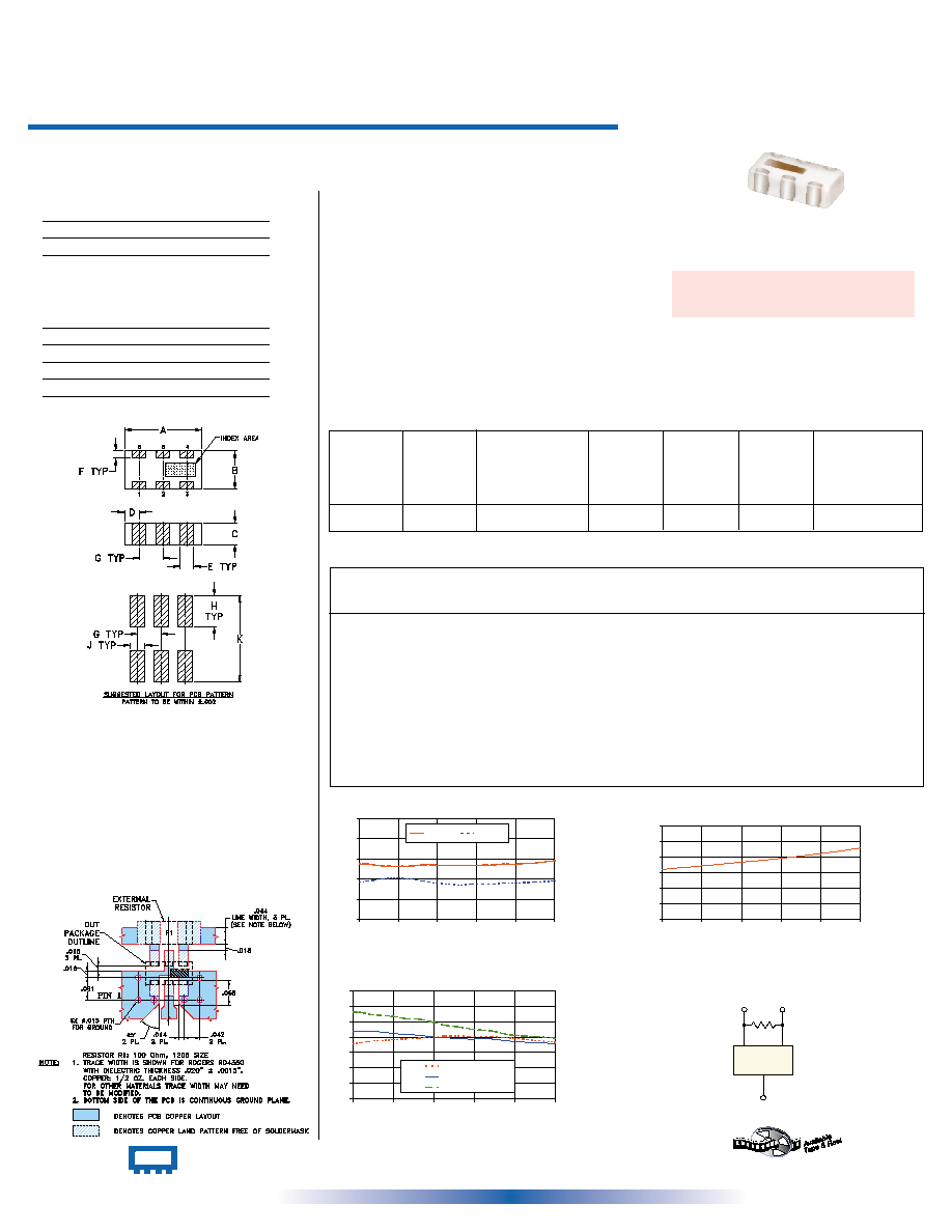
Outline Dimensions ( )
Outline Drawing
A
B
C
D
E
F
.126
.063
.037
.024
.022
.012
3.20
1.60
0.94
0.61
0.56
0.30
G
H
J
K
wt
.039
.042
.024
.123
grams
0.99
1.07
0.61
3.12
.020
inch
mm
+ RoHS compliant in accordance
with EU Directive (2002/95/EC)
See our web site for RoHS Compliance methodologies
and qualifi cations.
INTERNET http://www.minicircuits.com
P.O. Box 350166, Brooklyn, New York 11235-0003 (718) 934-4500 Fax (718) 332-4661
Distribution Centers
NORTH AMERICA 800-654-7949 ∑ 417-335-5935 ∑ Fax 417-335-5945 ∑ EUROPE 44-1252-832600 ∑ Fax 44-1252-837010
Mini-Circuits
Æ
Mini-Circuits ISO 9001 & ISO 14001 Certified
Demo Board MCL P/N: TB-252
Suggested PCB Layout (PL-129)