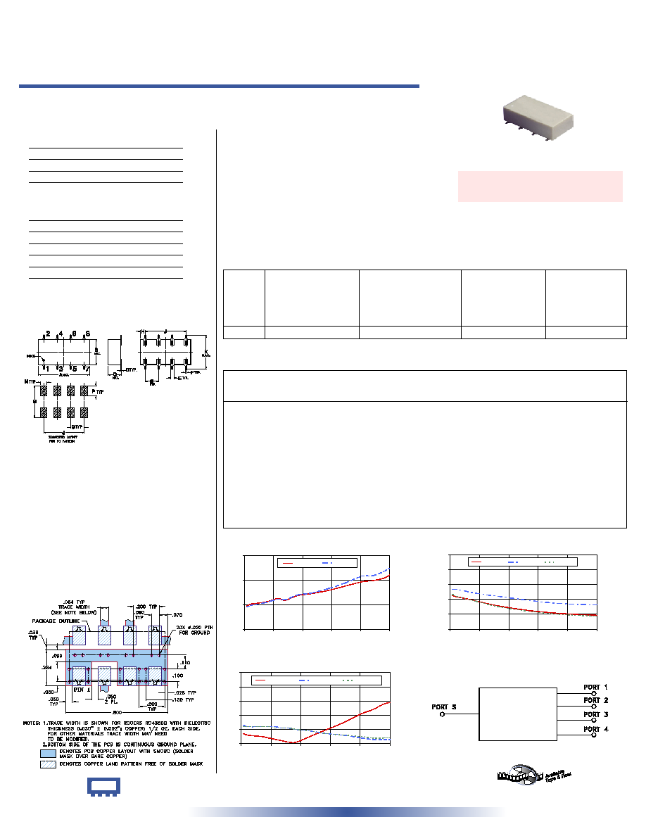
4 Way-0∞ 50
10 to 650 MHz
Power Splitter/Combiner
Surface Mount
SCP-4-1W+
SCP-4-1W
CASE STYLE: YY101
PRICE: $26.95 ea. QTY (1-9)
SCP-4-1W
INSERTION LOSS
6.0
6.4
6.8
7.2
0
130
260
390
520
650
FREQUENCY (MHz)
I
N
S
E
R
T
I
O
N
L
O
S
S
(
d
B
)
S-1(dB)
S-3(dB)
SCP-4-1W
ISOLATION
10
22
34
46
58
70
0
130
260
390
520
650
FREQUENCY (MHz)
I
S
O
L
A
T
I
O
N
(
d
B
)
1-2(dB)
2-3(dB)
3-4(dB)
SCP-4-1W
VSWR
1.0
1.1
1.2
1.3
1.4
1.5
0
130
260
390
520
650
FREQUENCY (MHz)
V
S
W
R
#S-VSWR
#1-VSWR
#3-VSWR
Demo Board MCL P/N: TB-36
Suggested PCB Layout (PL-073)
Outline Dimensions ( )
inch
mm
Maximum Ratings
Pin Connections
Features
∑ VHF/UHF
∑ receivers/transmitters
∑ federal and defense communication
SUM PORT
3
PORT 1
2
PORT 2
4
PORT 3
6
PORT 4
8
GROUND
1,5,7
∑ wideband, 10 to 650 MHz
∑ excellent amplitude unbalance, 0.4 dB typ.
Applications
Operating Temperature
-40∞C to 85∞C
Storage Temperature
-55∞C to 100∞C
Power Input (as a splitter)
1W max.
Internal Dissipation
0.25W max.
Outline Drawing
Splitter Electrical Specifications
L
Typ. Min.
M
Typ. Min.
U
Typ. Min.
FREQ.
RANGE
(MHz)
PHASE
UNBALANCE
(Degrees)
L
Max.
U
Max.
M
Max.
ISOLATION
(dB)
INSERTION LOSS (dB)
ABOVE 6 dB
L
Typ. Max.
M
Typ. Max.
U
Typ. Max.
AMPLITUDE
UNBALANCE
(dB)
L
Max.
U
Max.
M
Max.
f
L
-f
U
10-650
34 28
23 18 21 15 0.7 1.0 0.9 1.5 1.1 1.9
3
7
12
0.2
0.4
0.7
REV. B
M102713
SCP-4-1W
HY/TD/CP
060118
L = low range [f
L
to 10 f
L
] M = mid range [10 f
L
to f
U
/2] U = upper range [f
U
/2 to f
U
]
Freq.
(MHz)
Insertion Loss
(dB)
Amp.
Unbal.
(dB)
Isolation
(dB)
S-1
S-2
S-3
1-2
3-4
VSWR
S
Phase
Unbal.
(deg.)
VSWR
2
VSWR
3
VSWR
1
2-3
S-4
VSWR
4
Typical Performance Data
2
4
6
8
1
3
5
7
A
N
M
G
J
P
B
C
D
G
E
F
H
J
K
10.00
6.38
6.36
6.36
6.36
0.02
37.18 42.07 38.05
0.07
1.07
1.13
1.13
1.12
1.12
30.00
6.41
6.39
6.39
6.38
0.02
36.10 42.30 36.46
0.12
1.06
1.12
1.12
1.12
1.12
90.00
6.44
6.43
6.43
6.42
0.02
33.76 39.74 33.67
0.43
1.05
1.12
1.12
1.12
1.12
120.00
6.47
6.46
6.46
6.44
0.03
32.46 38.76 32.19
0.58
1.04
1.12
1.12
1.12
1.12
150.00
6.50
6.49
6.49
6.47
0.03
31.21 38.02 30.82
0.70
1.03
1.12
1.12
1.11
1.12
180.00
6.47
6.47
6.48
6.45
0.03
29.92 37.23 29.49
0.85
1.02
1.11
1.11
1.11
1.11
210.00
6.51
6.52
6.52
6.49
0.04
28.87 36.52 28.36
0.95
1.01
1.11
1.11
1.11
1.11
240.00
6.55
6.56
6.56
6.52
0.04
27.96 35.86 27.40
1.10
1.01
1.10
1.11
1.10
1.10
300.00
6.58
6.59
6.59
6.54
0.05
26.21 34.39 25.59
1.33
1.05
1.09
1.09
1.09
1.09
375.00
6.63
6.65
6.66
6.58
0.08
24.48 32.64 23.81
1.69
1.10
1.07
1.08
1.07
1.08
450.00
6.70
6.75
6.75
6.63
0.12
23.16 31.19 22.46
1.94
1.15
1.06
1.07
1.06
1.06
525.00
6.77
6.86
6.86
6.70
0.15
22.23 30.20 21.51
2.32
1.21
1.04
1.05
1.05
1.04
575.00
6.79
6.88
6.87
6.69
0.19
21.76 29.83 21.04
2.45
1.24
1.03
1.05
1.04
1.04
625.00
6.83
6.95
6.94
6.73
0.22
21.37 29.74 20.65
2.66
1.28
1.03
1.05
1.04
1.03
650.00
6.88
7.01
6.99
6.77
0.25
21.19 29.79 20.47
2.73
1.29
1.03
1.05
1.04
1.03
A
B
C
D
E
F
G
0.75
0.38
0.28
0.01
0.05
0.02
0.2
19.05
9.65
7.11
0.25
1.27
0.51
5.08
H
J
K
M
N
P
wt
0.075
0.6
0.45
0.47
0.1
0.15
grams
1.91
15.24
11.43
11.94
2.54
3.81
1.60
electrical schematic
INTERNET
http://www.minicircuits.com
P.O. Box 350166, Brooklyn, New York 11235-0003 (718) 934-4500 Fax (718) 332-4661
Distribution Centers NORTH AMERICA 800-654-7949 ∑ 417-335-5935 ∑ Fax 417-335-5945 ∑ EUROPE 44-1252-832600 ∑ Fax 44-1252-837010
Mini-Circuits
Æ
Mini-Circuits ISO 9001 & ISO 14001 Certified
+ RoHS compliant in accordance
with EU Directive (2002/95/EC)
The +Suffix identifies RoHS Compliance. See our web site
for RoHS Compliance methodologies and qualifications.