L = low range [f
L
to 10 f
L
] M = mid range [10 f
L
to f
U
/2] U= upper range [f
U
/2 to f
U
]
FREQ.
RANGE
(MHz)
ISOLATION
(dB)
INSERTION LOSS (dB)
ABOVE 3.0 dB
PHASE
UNBALANCE
(Degrees)
AMPLITUDE
UNBALANCE
(dB)
f
L
-f
U
L
M
U
L
M
U
L
M
U
L
M
U
Typ. Min Typ. Min Typ. Min Typ. Max. Typ. Max. Typ. Max. Max.
Max.
Max.
Max.
Max.
Max.
2-500
40
20
32
20
30
20
0.2
0.6
0.3 0.75 0.6
1.0
2.0
3.0
4.0
0.2
0.3
0.5
A
B
C
D
E
F
G
H
J
.375
.500
.23
.020
.075
.250
.425
.187
.050
9.53 12.70
5.84
0.51
1.91
6.35 10.80
4.75
1.27
K
L
M
N
P
Q
R
S
T
wt.
.050
.070
.270
.540
.060
.095
.445
.208
.415 grams
1.27
1.78
6.86 13.72
1.52
2.41 11.30
5.28 10.54
0.8
SYPS-2-1
2 Way-0� 50 2 to 500 MHz
Power Splitter/Combiner
Surface Mount
INTERNET
http://www.minicircuits.com
P.O. Box 350166, Brooklyn, New York 11235-0003 (718) 934-4500 Fax (718) 332-4661
Distribution Centers NORTH AMERICA 800-654-7949 � 417-335-5935 � Fax 417-335-5945 � EUROPE 44-1252-832600 � Fax 44-1252-837010
Mini-Circuits
�
Mini-Circuits ISO 9001 & ISO 14001 Certified
Typical Performance Data
Splitter Electrical Specifications
Maximum Ratings
Operating Temperature
-40�C to 85�C
Storage Temperature
-55�C to 100�C
Power Input (as a splitter)
1W max.
Internal Dissipation
0.125W max.
Outline Drawing
Outline Dimensions ( )
inch
mm
electrical schematic
REV.OR
M94166
SYPS-2-1
HY/TD/CP
060830
CASE STYLE: TTT167
PRICE: $7.95 ea. QTY. (1-9)
Features
� wideband, 2 to 500 MHz
� low insertion loss, 0.3 dB typ.
� high isolation, 32 dB typ.
Applications
� VHF/UHF
� communications systems
� receivers & transmitters
� instrumentation
Pin Connections
SUM PORT
3
PORT 1
1
PORT 2
2
GROUND
4,5,6
Demo Board MCL P/N: TB-12
Suggested PCB Layout (PL-079)
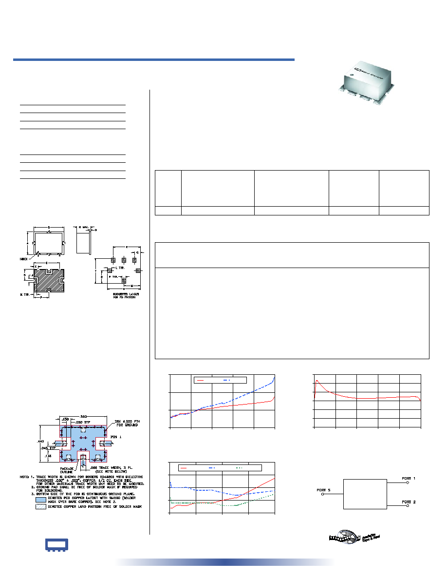
SYPS-2-1
INSERTION LOSS
3.0
3.2
3.4
3.6
0
100
200
300
400
500
FREQUENCY (MHz)
INSERTION
LOSS
(dB)
S-1(dB)
S-2(dB)
SYPS-2-1
ISOLATION
20
25
30
35
40
45
50
0
100
200
300
400
500
FREQUENCY (MHz)
ISOLATION (dB)
SYPS-2-1
VSWR
1.00
1.05
1.10
1.15
1.20
0
100
200
300
400
FREQUENCY (MHz)
V
S
W
R
#S-VSWR
#1-VSWR
#2-VSWR
Frequency
(MHz)
Insertion Loss
(dB)
Amplitude
Unbalance
(dB)
Isolation
(dB)
Phase
Unbalance
(deg.)
VSWR
S
VSWR
1
VSWR
2
S-1
S-2
2.84
3.12
3.12
0.00
36.81
0.01
1.02
1.12
1.06
4.47
3.11
3.12
0.00
40.46
0.02
1.02
1.11
1.05
7.03
3.11
3.11
0.00
44.30
0.01
1.02
1.10
1.04
10.86
3.13
3.12
0.01
46.85
0.03
1.02
1.10
1.04
26.91
3.13
3.14
0.00
44.74
0.07
1.03
1.10
1.04
49.59
3.16
3.15
0.00
41.78
0.08
1.03
1.10
1.04
66.66
3.16
3.15
0.00
40.46
0.18
1.03
1.10
1.04
100.87
3.17
3.17
0.00
38.79
0.28
1.04
1.09
1.04
149.64
3.21
3.22
0.01
37.29
0.35
1.04
1.09
1.04
161.93
3.21
3.23
0.01
37.11
0.39
1.04
1.09
1.04
201.16
3.22
3.25
0.03
36.51
0.47
1.05
1.08
1.03
249.89
3.24
3.28
0.04
36.36
0.52
1.06
1.07
1.03
254.97
3.24
3.27
0.03
36.38
0.59
1.06
1.07
1.03
479.07
3.30
3.50
0.20
37.41
0.80
1.18
1.10
1.10
498.34
3.35
3.57
0.22
35.04
0.75
1.20
1.12
1.12