INTERNET http://www.minicircuits.com
P.O. Box 350166, Brooklyn, New York 11235-0003 (718) 934-4500 Fax (718) 332-4661
Distribution Centers NORTH AMERICA 800-654-7949 ∑ 417-335-5935 ∑ Fax 417-335-5945 ∑ EUROPE 44-1252-832600 ∑ Fax 44-1252-837010
Mini-Circuits
Æ
ISO 9001 CERTIFIED
178
020710
features
l
wide bandwidth, 0.5-1000 MHz
l
instrument model, with built-in power supply,110/220V operation
l
high power output,
(at 3.5 dB compression)
45 dBm typical for TIA-900-10
42 dBm typical for TIA-1000-4
37 dBm typical for TIA-1000-1R8
l
high gain,
38 dB typical for TIA-1000-1R8
34 dB typical for TIA-900-10
l
high reverse isolation,
80 dB typical for TIA-900-10, TIA-1000-1R8
55 dB typical for TIA-1000-4
l
100% Burn-In at +25
o
C, 48 hours
l
thermally self-protected, led indicator
NOTES:
*
NF above 400 MHz. At low frequency, NF Increases to 16 dB Typ.
C.
Prices and Specifications subject to change without notice.
D.
For Quality Control Procedures see Table of Contents, Section 0,
see "Mini-Circuits Guarantees Quality" article.
1.
For TIA-1000 models, add dash 2 (-2) to model no. for 220V
operation.
2.
Gain and maximum output power specified at 25
o
C±5
o
C., over
temperature, specifications degrade approximately 1dB, gain
flatness ±2.5dB maximum for TIA-10001R8 and TIA-1000-4.
3.
Open load is not recommended, potentially can cause
damage. With no load, derate max input power by 20 dB.
4.
VSWR specified at:
350-900 MHz for TIA-900-10
350-1000 MHz for TIA-1000-4
340-1000 MHz for TIA-1000-1R8
5.
Operating temperature: 0
o
C to +55
o
C.
Storage temperature: -40
o
C to +70
o
C.
6.
All TIA models are protected under U.S. patent 5, 101, 171.
TIA
up to 10W (+40 dBm) output
A
MPLIFIERS
50
RF Instrument
H
IGH
P
OWER
0.5 to 1000 MHz
case
wt.
no.
A
B
C
D
grams
NOTES
AP175
inch
9.8
5.0
6.7
0.2
3500
A10, D7, G1, G2
mm 248.9 127.0 170.2
5.1
AP176
inch
19.5
6.0
12.5
0.2
9500
A10, D7, G1, G2
mm 495.3 152.4 317.5
5.1
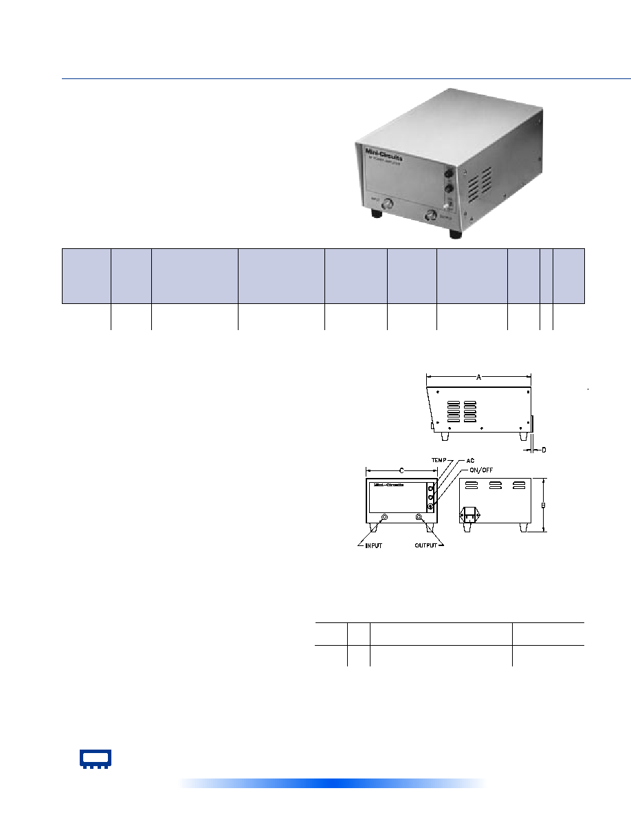
Outline drawing and dimensions
A10. Case material: aluminum alloy. Finish: grey paint.
D7.
Connectors: BNC only.
G1.
Keep area adjacent to fan and louvers clear to permit air flow to pass.
Caution: Do not insert anything especially conductors or fingers into
case opening. Physical injury, shock or death may occur.
G.2
Configured for either 110 volt or 220 volt AC operation; specify when
ordering.
GAIN
(dB)
MAXIMUM POWER
(dBm)
f
L
-f
U
AC
POWER
FREQ.
(MHz)
MODEL
NO.
C
O
N
N
E
C
T
I
O
N
CASE
STYLE
Qty.
(1-9)
PRICE
$
VSWR
DYNAMIC
RANGE
Input
Max.
(no
damage)
Output
(1 dB
Comp.)
Typ. Min.
Min.
IP3
(dBm)
Typ.
In
Out
Volt
(note1)
VA
Max.
Flatness
Max.
NF
(dB)
Typ.
Freq.
Hz
TIA-900-10
100-900
28
±2.5
+42
+40
+25
13
51
2.5:1
2.5:1
110
50/60
475
AP176
-- 3,695.00
TIA-1000-4
100-1000
19
±1.5
+39
+36
+25
12
48
2.5:1
2.5:1
110
50/60
400
AP176
-- 1,995.00
TIA-1000-1R8
0.50-1000
35
±2.0
+35
+32
+7
8*
45
1.9:1
2.5:1
110
50/60
140
AP175
-- 1,495.00

The Design Engineers Search Engine
Provides Actual Data Instantly
At:
http://www.minicircuits.com
In Stock... Immediate Delivery
For Custom Versions Of Standard Models
Consult Our Applications Dept.
Mini-Circuits
Æ
179
V
ERY
H
IGH
P
OWER
50W, 20 to 1000MHz
features
l
saturated power 50W typ. (LZY-1) and 32W typ. (LZY-2)
l
high power with low distortion, -32 dBc typ. (LZY-1) and -45 dBc typ.
(LZY-2) harmonics at 20 watts
l
wide bandwidth, usable 10 - 525 MHz and 475 - 1050 MHz
l
high gain, 42 dB typ. (LZY-1) and 47 dB typ. (LZY-2)
l
unconditionally stable
l
self protected against excessive drive, high case temp., reverse
polarity and shorting/unshorting transients at dc input
l
electronic shutoff by grounding the shut-off terminal, reduces
output by 50 dB. Open
circuiting terminal restores full power within
100 µ sec.
l
cool operation with integral fan, 15∞ C typ. rise
l
graceful degradation, +20 to +30V DC
l
can withstand short and open circuit at output for 2 minutes while
delivering 20
watts
NOTES:
*
80-512 MHz, at 20 MHz 11.6 dB typ.
**
At 25W output for LZY-1 and 20W for LZY-2; includes fan
B.
Connector types and case mounted options, case finishes
are given in section 0, see "Case styles & Outline Drawings".
C.
Prices and Specifications subject to change without notice.
D.
For Quality Control Procedures see Table of Contents, Section 0,
"Mini-Circuits Guarantees Quality" article. For environmental
Specifications see Amplifier Selection Guide.
1.
Absolute max. dc voltage: +30V
2.
Operating air-ambient temp. for specified performance:
-10∞C to 50∞C
3.
Max. storage temp.: -55∞C to 100∞C
i
VSWR 9:1 typ. up to 450 MHz, all specifications for 50 ohm load.
Self-Cooled
020710
up to 50W (+47 dBm) output
LZY-X
LZY
e
To order without heat sink and fan, add suffix -X to model number.
Alternative heat sinking and heat removal must be provided by customer to
ensure proper performance. See application note AN-60-004 for LZY-1,
AN-60-005 for LZY-2 . Deduct $100 from price list.
e
GAIN
(dB)
POWER
(dBm)
f
L
-f
U
DC
POWER
FREQ.
(MHz)
MODEL
NO.
C
O
N
N
E
C
T
I
O
N
CASE
STYLE
Qty.
(1-9)
PRICE
$
Note B
VSWR
DYNAMIC
RANGE
Max.
Input
(no
damage)
Min.
Output
(1 dB
Comp.)
Min.
IP3
(dBm)
Typ.
In
Out
Volt
(V)
Max.
Current**
(A)
Flatness
Max.
NF
(dB)
Typ.
Max.
Output
Typ.
LZY-1
20 - 512
39
±1.5
+44
+47
+10
8.6*
54
2.0:1
i
+26
7.3
BT412
-- 1995.00
LZY-2
500 -1000
40
±1.5
+43
+45
+10
8.0
54
2.0:1
3.5:1
+28
8.0
BT451
-- 2195.00