50
DC to 2000 MHz
Monolithic Amplifiers
Surface Mount
VAM+ SERIES
VAM SERIES
CASE STYLE: MMM168
Maximum Ratings
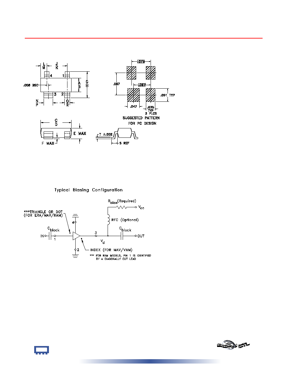
Pin Connections
Features
RF IN
1
RF OUT
3
DC
3
GROUND
2,4
Operating Temperature
-20∞C to 85∞C
Storage Temperature
-55∞C to 100∞C
Electrical Specifications
REV. OR
M98898
VAM SERIES
051130
Page 1 of 2
∑ wideband, DC to 2000MHz
∑ cascadable
∑ protected by US Patent, 6,943,629 (except for VAM-6)
MODEL
NO.
FREQ.
(MHz)
GAIN (dB)
Typical at GHz
MAXIMUM
POWER
(dBm)
DYNAMIC
RANGE
VSWR
(:1)
Typ.
ABSOLUTE
MAXIMUM
RATING
6
(25∫)
DC
OPERATING
POWER
7
at Pin 3
THERMAL
RESISTANCE
5
PRICE
$
f
L
f
U
0.1
1
2
Note 1
Min.
Output
(1 dB
Compr.)
Typ.
Input
(no dam-
age)
NF
(dB)
Typ.
IP3
(dBm)
Typ.
In
Out
I
(mA)
P
(mW)
Cur-
rent
(mA)
Device
Volt
Typ.
∫C/W
Qty.
(30)
VAM-3
(+)
DC
2000
11.5
11.0
9.5
7.5
+9.0
+13
6.0
+22.0
1.5
1.7
60
240
35
4.70
500
1.19
VAM-6
(+)
DC
2000
19.5
15.0
10.0
8.0
+2.0
+13
3.0
+14.0
1.6
1.5
40
125
16
3.30
505
1.16
VAM-7
(+)
DC
2000
13.0
12.0
9.8
7.8
+5.5
+13
5.0
+18.0
1.5
1.5
50
175
22
3.80
505
1.31
Applications
∑ cellular
∑ PCN
∑ instrumentation
∑ UHF/VHF
NOTES:
1. Minimum gain at highest frequency at full temperature range, except roomtemperature for Dash-4 models.
2. Low frequency cutoff determined by external coupling capacitors.
3. Frequency at which output power, NF and IP3 are specified: 500 MHz for VAM-6(+).
4. VAM-6(+) potentially unstable with very high VSWR terminations.
5. Thermal resistance
jc is from hottest junction in device to mounting surface of leads.
6. Permanent damage may occur if any of these limits are exceeded. These ratings are not intended for
continuous normal operation.
7. Supply voltage must be connected to pin 3 through a bias resistor in order to prevent damage. See "Biasing
MMIC Amplifiers" in minicircuits.com/application.html. Reliability predictions are applicable at specified current
& normal operating conditions.
+ RoHS compliant in accordance
with EU Directive (2002/95/EC)
See our web site for RoHS Compliance methodologies
and qualifications.
1
10
100
1,000
10,000
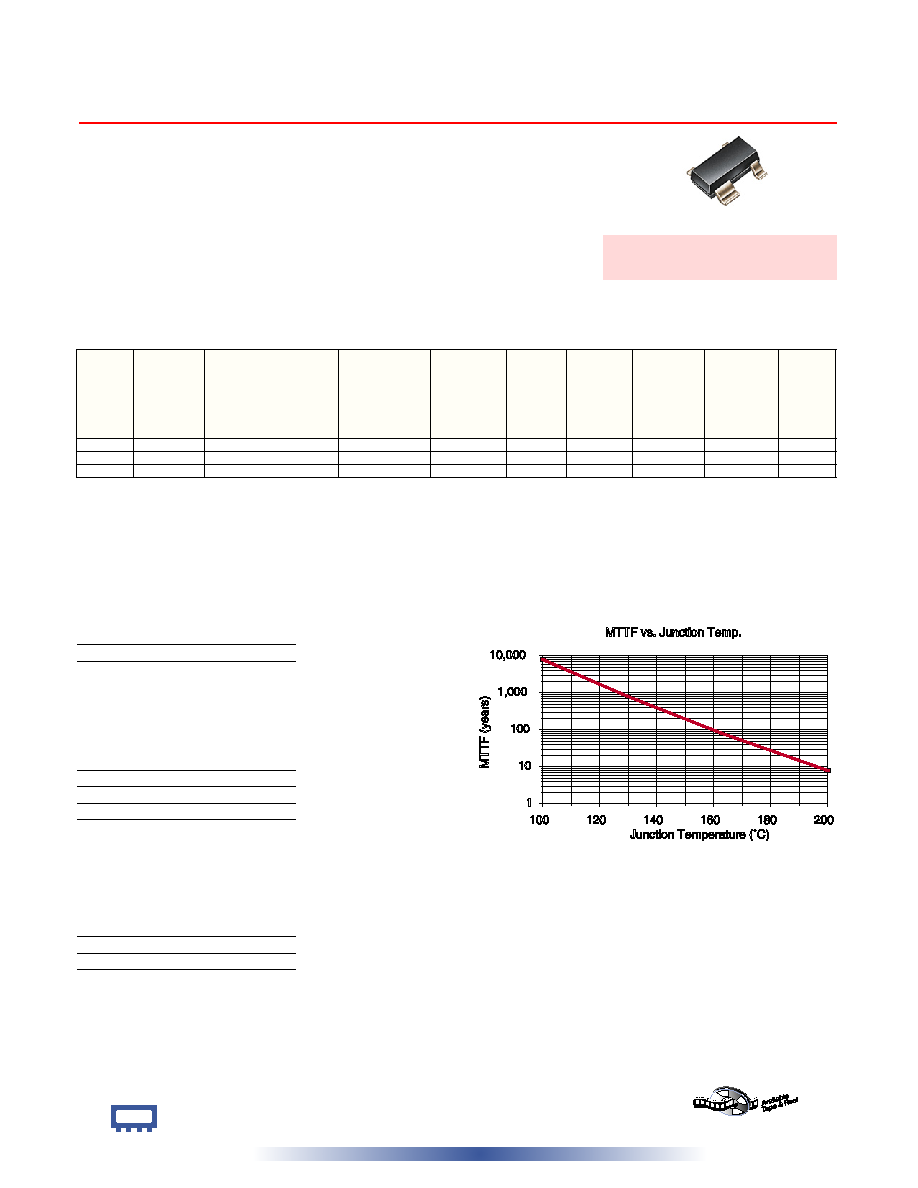
M
T
T
F
(
y
e
a
r
s
)
100
120
140
160
180
200
Junction Temperature (∞C)
MTTF vs. Junction Temp.
Model Identification
VAM-3(+)
03
VAM-6(+)
06
VAM-7(+)
07
INTERNET
http://www.minicircuits.com
P.O. Box 350166, Brooklyn, New York 11235-0003 (718) 934-4500 Fax (718) 332-4661
Distribution Centers NORTH AMERICA 800-654-7949 ∑ 417-335-5935 ∑ Fax 417-335-5945 ∑ EUROPE 44-1252-832600 ∑ Fax 44-1252-837010
Mini-Circuits
Æ
Mini-Circuits ISO 9001 & ISO 14001 Certified
A
B
C
D
E
F
G
H
J
K
L
M
N
P
Q
R
S
T
wt.
.045 .055 .105 .120 .047 .005 .083 .104 .070 .080 .018 .024 .030 .036 .015
.021
.023
.004 grams
1.14 1.40 2.67 3.05 1.19 0.13 2.11 2.64 1.78 2.03 0.46 0.61 0.76 0.91 0.38
0.53
0.58
0.10
.01
Outline Dimensions ( )
inch
mm
Outline Drawing
Page 2 of 2
VAM+ SERIES
VAM SERIES
INTERNET
http://www.minicircuits.com
P.O. Box 350166, Brooklyn, New York 11235-0003 (718) 934-4500 Fax (718) 332-4661
Distribution Centers NORTH AMERICA 800-654-7949 ∑ 417-335-5935 ∑ Fax 417-335-5945 ∑ EUROPE 44-1252-832600 ∑ Fax 44-1252-837010
Mini-Circuits
Æ
Mini-Circuits ISO 9001 & ISO 14001 Certified