INTERNET
http://www.minicircuits.com
P.O. Box 350166, Brooklyn, New York 11235-0003 (718) 934-4500 Fax (718) 332-4661
Distribution Centers NORTH AMERICA 800-654-7949 ∑ 417-335-5935 ∑ Fax 417-335-5945 ∑ EUROPE 44-1252-832600 ∑ Fax 44-1252-837010
Mini-Circuits
Æ
Mini-Circuits ISO 9001 & ISO 14001 Certified
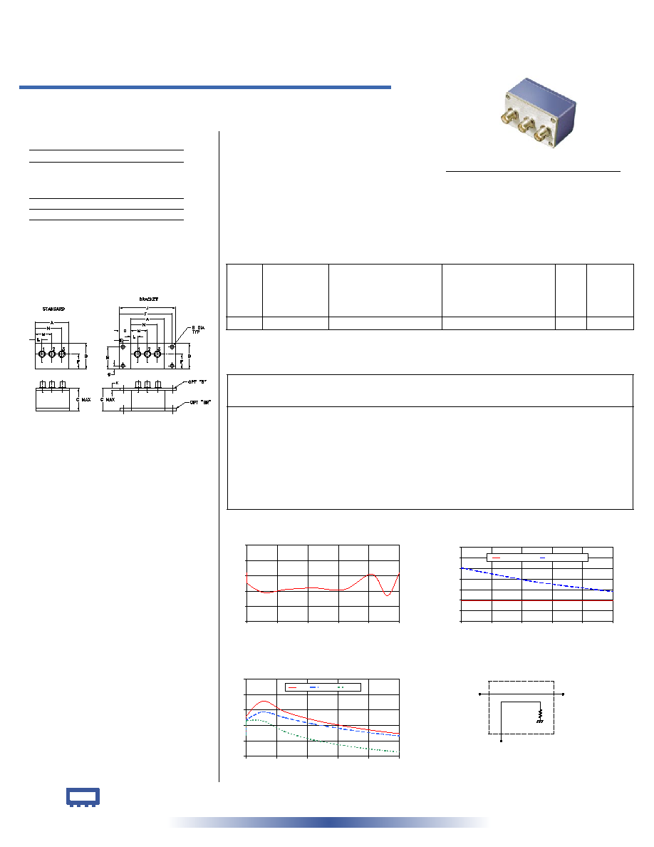
Typical Performance Data
Directional Coupler Electrical Specifications
Maximum Ratings
Coaxial Connections
INPUT
3
OUTPUT
2
COUPLED
1
Operating Temperature
-55∞C to 100∞C
Storage Temperature
-55∞C to 100∞C
Outline Drawing
Outline Dimensions ( )
inch
mm
ZDC-20-3
MAINLINE LOSS
0.0
0.1
0.2
0.3
0.4
0.5
0
50
100
150
200
250
FREQUENCY (MHz)
MAINLINE
LOSS
(dB)
at RF level of -10 dBm
ZDC-20-3
COUPLING & DIRECTIVITY
0
10
20
30
40
50
60
70
0
50
100
150
200
250
FREQUENCY (MHz)
C
O
U
P
L
I
N
G
&
D
I
R
E
C
T
I
V
I
T
Y
(
d
B
)
COUPLING
DIRECTIVITY
at RF level of -10 dBm
ZDC-20-3
ZDC-20-3
RETURN LOSS
10
18
26
34
42
50
0
50
100
150
200
250
FREQUENCY (MHz)
RETURN
LOSS
(dB)
IN
OUT
CPL
at RF level of -10 dBm
electrical schematic
INPUT
OUTPUT
COUPLED
50 0.2 to 250 MHz
Directional Coupler
REV. OR
M93849
ZDC-20-3
WZ/TD/CP
060801
Coaxial
A
B
C
D
E
F
G
H
2.25
1.38
1.24
.50
.150 3.100
.138 1.238
57.15 35.05 31.50 12.70
3.81 78.74
3.51 31.45
J
K
L
M
N
P
S
wt
3.25
.10
.40
1.15
1.86
.64
.150 grams
82.55
2.54 10.16 29.21 47.24 16.26
3.81
74.0
CASE STYLE: M22
Connectors Model
Price
Qty.
BNC
ZDC-20-3
$45.95 ea. (1-9)
BRACKET (OPTION"B")
$5.00
(1+)
BRACKET (OPTION"BR")
$1.50
(1+)
Frequency
(MHz)
Mainline Loss
(dB)
In-Out
Coupling
(dB)
In-Cpl
Directivity
(dB)
In
Return Loss
(dB)
Out
Cpl
Features
∑ excellent directivity, 33 dB typ.
∑ excellent insertion loss, 0.25 dB typ.
∑ rugged shielded case
Applications
∑ HF/VHF/UHF
∑ instrumentation
∑ communication receivers & transmitters
∑ amateur radio
FREQ.
RANGE
(MHz)
COUPLING
(dB)
MAINLINE LOSS
1
DIRECTIVITY
(dB)
VSWR
(:1)
POWER
INPUT
(W)
L
M
U
L
M
U
L
MU
f
L
-f
U
Nom.
Flatness Typ. Max. Typ. Max. Typ. Max. Typ. Min. Typ. Min. Typ. Min.
Typ.
Max.
Max.
0.2-250
19.5±0.5
±0.5
0.35
0.6
0.25
0.5
0.35
0.6
36
30
33
25
25
20
1.2
1.5
4.0
L = low range [f
L
to 10 f
L
] M = mid range [10 f
L
to f
U
/2] U= upper range [f
U
/2 to f
U
]
1. Mainline loss includes theoretical power loss at coupled port.
0.20
0.32
19.34
50.22
21.46
21.09
20.80
0.60
0.28
19.37
49.85
28.15
26.69
26.38
1.00
0.25
19.33
50.58
30.85
28.75
28.35
28.00
0.19
19.29
47.42
38.60
33.01
28.36
64.00
0.21
19.31
43.53
33.07
30.00
22.73
110.00
0.22
19.40
38.54
28.85
26.79
18.52
160.00
0.21
19.42
34.38
25.72
24.09
15.58
205.00
0.31
19.64
31.27
23.51
22.14
13.69
230.00
0.17
19.51
29.52
22.48
21.25
12.86
250.00
0.32
19.82
28.26
21.75
20.60
12.29