INTERNET http://www.minicircuits.com
P.O. Box 350166, Brooklyn, New York 11235-0003 (718) 934-4500 Fax (718) 332-4661
Distribution Centers NORTH AMERICA 800-654-7949 ∑ 417-335-5935 ∑ Fax 417-335-5945 ∑ EUROPE 44-1252-832600 ∑ Fax 44-1252-837010
Mini-Circuits
Æ
ISO 9001 CERTIFIED
020710
v ZFRSC-42
DC-4200
6.2
6.5
7.0
0.1
0.2
0.1
0.5
0.4
1.4
1
3
5
0.1
0.2
0.5
K18
ar
59.95
n ZFRSC-2075
DC-2000
6.2
6.6
7.0
0.1
0.2
0.3
0.6
0.5
1.4
1
2
5
0.1
0.2
0.5
K18
ar
59.95
ZFRSC-2050
DC-2000
6.2
6.6
7.0
0.1
0.2
0.3
0.6
0.5
1.4
1
2
5
0.1
0.2
0.5
K18
ar
59.95
PRSC-2050
DC-2000
6.0
6.2
6.5
0.1
0.3
0.2
0.7
0.5
1.0
1
3
5
0.1
0.3
0.5
C145
au
31.95
ZFRSC
L = DC to 100 MHz
M = mid range [100 MHz to f
U
/2]
U = upper range [f
U
/2 to f
U
]
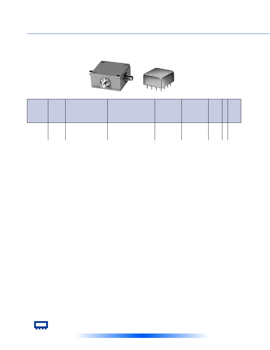
Above models are resistive power dividers to enable frequency coverage from dc to the highest rated frequency. Since
resistive power dividers do not provide a high degree of isolation (basically isolation equals the insertion loss between
ports), an amplifier such as Mini-Circuits' ZFL series is recommended when high isolation is required. Matched power
rating 0.75W, internal load dissipation 0.375W.
PRSC
NOTES:
n
Denotes 75 Ohm model, for coax connector models 75 Ohm
BNC connectors are standard.
v
Available only with SMA connectors
A.
General Quality Control Procedures, Environmental Specifica-
tions, Hi-Rel and MIL description are given in General
Information (Section 0).
B.
Connector types and case mounted options, case finishes are
given in section 0, see "Case styles & Outline Drawings".
C.
Prices and specifications subject to change without notice.
1.
Absolute maximum power, voltage and current ratings:
1a. Matched power rating,
Model ZAPDQ ....................... 10 Watt
all other models ................... 1 Watt
1b. Internal load dissipation ...... 0.125 Watt
122
ISOLATION
dB
INSERTION LOSS, dB
Above 6dB
PHASE
UNBALANCE
Degrees
f
L
-f
U
M
Max.
L
Max.
U
Max.
AMPLITUDE
UNBALANCE
dB
U
Max.
M
Max.
L
Max.
FREQ.
RANGE
MHz
MODEL
NO.
M
Typ.
L
Typ.
U
Typ.
L
Typ. Max.
M
Typ. Max.
U
Typ. Max.
C
O
N
N
E
C
T
I
O
N
CASE
STYLE
Qty.
(1-9)
PRICE
$
Note B
P
OWER
S
PLITTERS
/C
OMBINERS
2 W
AY
-0∞ R
ESISTIVE
DC to 4200 MHz
50
The Design Engineers Search Engine
Provides Actual Data Instantly
At:
http://www.minicircuits.com
In Stock... Immediate Delivery
For Custom Versions Of Standard Models
Consult Our Applications Dept.
Mini-Circuits
Æ
Æ
123
pin and coaxial connections
see case style outline drawings for pin connections
PORT
ar
at
au
SUM PORT
3
2
5
PORT 1
1
1
3
PORT 2
2
3
15
GND EXT.
--
--
1,2,4,8,9,12,13,14,16
CASE GND
--
--
1,2,4,8,9,12,13,14,16
ZAPDQ-2
1000-2000
22
16
0.4
1.4
6.0
0.8
F14
ar
79.95
ZAPDQ-4
2000-4200
22
16
0.4
0.9
8.0
1.0
F14
ar
79.95
ZMSCQ-2-50
25-50
30
20
0.3
0.7
3.0
1.5
M21
at
61.95
ZMSCQ-2-90
55-90
30
20
0.3
0.7
3.0
1.2
M21
at
61.95
ZMSCQ-2-120
80-120
25
18
0.3
0.7
3.0
1.5
M21
at
61.95
ZMSCQ-2-180
120-180
23
15
0.3
0.7
4.0
1.2
M21
at
61.95
ZSCQ-2-90
55-90
30
20
0.3
0.7
3.0
1.2
M22
at
54.95
ZMSCQ-2
ZSCQ-2
NSN GUIDE
MCL NO.
NSN
ZAPDQ-4
5985-01-412-9064
ZMSCQ-2-250
5985-01-394-4982
ZFRSC-2050B
5985-01-310-5748
ZFRSC-2075
5985-01-266-6144
ZFRSC-42
5985-01-332-3083
L = low range [f
L
to 10 f
L
]
M = mid range [10 f
L
to f
U
/2]
U = upper range [f
U
/2 to f
U
]
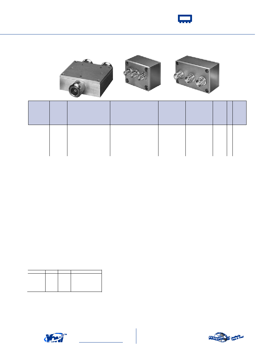
ZAPDQ
030717
ISOLATION
dB
INSERTION LOSS, dB
Avg. of Coupled Outputs
less 3 dB
PHASE
UNBALANCE
Degrees
f
L
-f
U
Max.
AMPLITUDE
UNBALANCE
dB
Max.
FREQ.
RANGE
MHz
MODEL
NO.
Typ. Min.
C
O
N
N
E
C
T
I
O
N
CASE
STYLE
Qty.
(1-9)
PRICE
$
Note B
Typ. Max.
Plug-In & Coaxial
2 W
AY
-90∞
25 to 4200 MHz