L = low range [f
L
to 10 f
L
] M = mid range [10 f
L
to f
U
/2] U= upper range [f
U
/2 to f
U
]
FREQ.
RANGE
(MHz)
ISOLATION
(dB)
INSERTION LOSS (dB)
ABOVE 3.0 dB
PHASE
UNBALANCE
(Degrees)
AMPLITUDE
UNBALANCE
(dB)
f
L
-f
U
L
M
U
L
M
U
L
M
U
L
M
U
Typ. Min Typ. Min Typ. Min Typ. Max. Typ. Max. Typ. Max. Max.
Max.
Max.
Max.
Max.
Max.
1-750
30
20
28
20
25
20
0.2
0.5
0.4
0.8
0.8
1.0
2
4
4
0.15
0.15
0.30
A
B
C
D
E
F
G
H
1.25
1.25
.75
.63
.38
1.00
.125 1.000
31.75
31.75
19.05
16.00
9.65
25.40
3.18 25.40
J
K
L
M
N
P
Q
wt
--
--
.125
1.688
2.18
.75
.07 grams
--
--
3.18
42.88
55.37
19.05
1.78
70.0
ZFSC-2-1W
2 Way-0� 50 1 to 750 MHz
Power Splitter/Combiner
Coaxial
INTERNET
http://www.minicircuits.com
P.O. Box 350166, Brooklyn, New York 11235-0003 (718) 934-4500 Fax (718) 332-4661
Distribution Centers NORTH AMERICA 800-654-7949 � 417-335-5935 � Fax 417-335-5945 � EUROPE 44-1252-832600 � Fax 44-1252-837010
Mini-Circuits
�
Mini-Circuits ISO 9001 & ISO 14001 Certified
Typical Performance Data
Maximum Ratings
Operating Temperature
-55�C to 100�C
Storage Temperature
-55�C to 100�C
Power Input (as a splitter)
1W max.
Internal Dissipation
0.125W max.
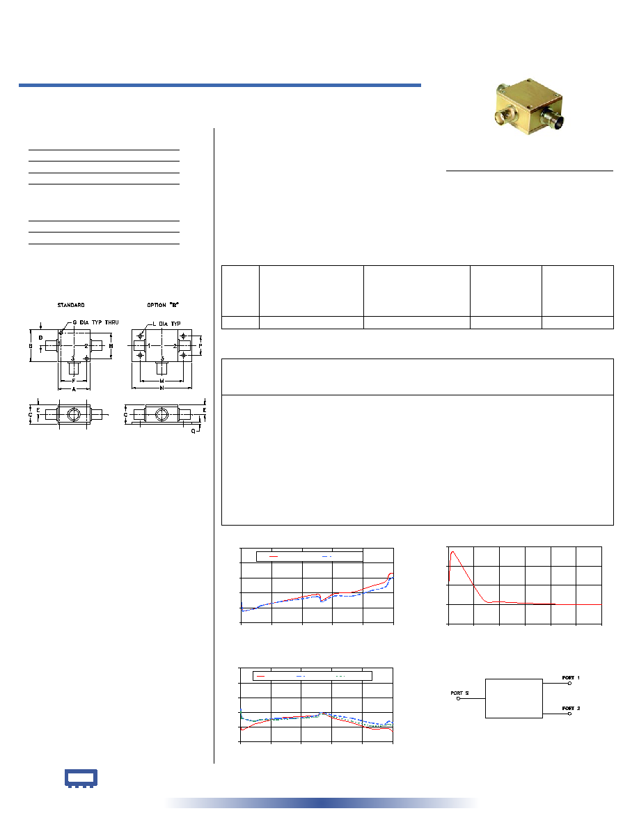
Outline Drawing
Outline Dimensions ( )
inch
mm
electrical schematic
REV. OR
M94482
ZFSC-2-1W
HY/TD/CP
060915
Features
� low insertion loss, 0.4 dB typ.
� high isolation, 28 dB typ.
� excellent amplitude unbalance, 0.1 dB typ.
� excellent phase unbalance, 0.5 deg. typ.
� very good return loss, VSWR, 1.15:1 typ.
� rugged shielded case
Applications
� VHF/UHF
� federal & defense communication
Coaxial Connections
SUMPORT
3
PORT 1
1
PORT 2
2
CASE STYLE: K18
Connectors Model
Price
Qty.
BNC
ZFSC-2-1W
$48.95 (1-9)
SMA
ZFSC-2-1W-S
$53.95
(1-9)
N-TYPE
ZFSC-2-1W-N
$53.95
(1-9)
BRACKET (OPTION "B")
$2.50
(1+)
ZFSC-2-1W
INSERTION LOSS
3.0
3.2
3.4
3.6
3.8
4.0
0
150
300
450
600
750
FREQUENCY (MHz)
INSERTION
LOSS
(dB)
S-1(dB)
S-2(dB)
ZFSC-2-1W
ISOLATION
20
25
30
35
40
0
50
100
150
200
250
300
FREQUENCY (MHz)
ISOLATION
(dB)
ZFSC-2-1W
VSWR
1.0
1.1
1.2
1.3
1.4
1.5
0
150
300
450
600
750
FREQUENCY (MHz)
V
S
W
R
#S-VSWR
#1-VSWR
#2-VSWR
Splitter Electrical Specifications
Frequency
(MHz)
Insertion Loss
(dB)
Amplitude
Unbalance
(dB)
Isolation
(dB)
Phase
Unbalance
(deg.)
VSWR
S
VSWR
1
VSWR
2
S-1
S-2
BNC version shown
For option B with N-type connectors, dimension "C" increases to 0.94 inches.
1.00
3.27
3.27
0.00
31.01
0.01
1.10
1.22
1.21
5.00
3.17
3.16
0.01
38.19
0.02
1.08
1.17
1.16
10.00
3.16
3.16
0.00
38.65
0.14
1.08
1.16
1.16
68.00
3.19
3.19
0.01
26.38
0.07
1.12
1.14
1.14
97.00
3.23
3.23
0.00
25.75
0.09
1.13
1.15
1.15
184.00
3.28
3.28
0.01
25.18
0.09
1.16
1.16
1.15
271.00
3.33
3.31
0.02
24.97
0.20
1.17
1.16
1.16
380.00
3.38
3.35
0.03
24.99
0.24
1.18
1.18
1.17
395.00
3.30
3.28
0.02
24.95
0.21
1.20
1.20
1.19
460.00
3.39
3.36
0.03
25.18
0.22
1.16
1.18
1.17
550.00
3.41
3.36
0.05
25.42
0.31
1.13
1.16
1.14
640.00
3.49
3.43
0.06
25.07
0.36
1.09
1.13
1.11
710.00
3.55
3.48
0.07
23.78
0.48
1.09
1.12
1.11
730.00
3.65
3.58
0.07
23.32
0.59
1.09
1.14
1.12
750.00
3.67
3.61
0.07
22.79
0.58
1.07
1.13
1.11