L = low range [f
L
to 10 f
L
] M = mid range [10 f
L
to f
U
/2] U= upper range [f
U
/2 to f
U
]
FREQ.
RANGE
(MHz)
ISOLATION
(dB)
INSERTION LOSS (dB)
ABOVE 4.8 dB
PHASE
UNBALANCE
(Degrees)
AMPLITUDE
UNBALANCE
(dB)
f
L
-f
U
L
M
U
L
M
U
L
M
U
L
M
U
Typ. Min Typ. Min Typ. Min Typ. Max. Typ. Max. Typ. Max. Max.
Max.
Max.
Max.
Max.
Max.
1-1000
35
20
20
18
20
17
0.2
0.5
0.7
1.4
1.0
2.0
3
6
10
0.2
0.4
0.9
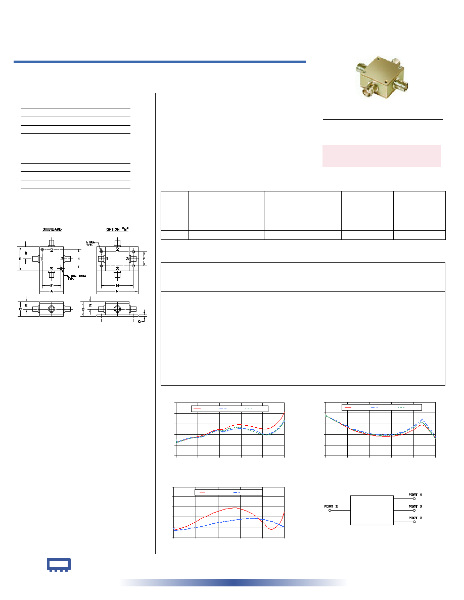
ZFSC-3-4
INSERTION LOSS
4.5
4.9
5.3
5.7
6.1
6.5
0
200
400
600
800
1000
FREQUENCY (MHz)
INSERTION
LOSS
(dB)
S-1(dB)
S-2(dB)
S-3(dB)
ZFSC-3-4
ISOLATION
10
16
22
28
34
40
0
200
400
600
800
1000
FREQUENCY (MHz)
ISOLATION
(dB)
1-2 (dB)
1-3 (dB)
2-3 (dB)
INTERNET
http://www.minicircuits.com
P.O. Box 350166, Brooklyn, New York 11235-0003 (718) 934-4500 Fax (718) 332-4661
Distribution Centers NORTH AMERICA 800-654-7949 � 417-335-5935 � Fax 417-335-5945 � EUROPE 44-1252-832600 � Fax 44-1252-837010
Mini-Circuits
�
Mini-Circuits ISO 9001 & ISO 14001 Certified
Typical Performance Data
Maximum Ratings
Coaxial Connections
SUMPORT
S
PORT 1
1
PORT 2
2
PORT 3
3
Operating Temperature
-55�C to 100�C
Storage Temperature
-55�C to 100�C
Power Input (as a splitter)
1W max.
Internal Dissipation
0.375W max.
Outline Drawing
Outline Dimensions ( )
inch
mm
ZFSC-3-4+
ZFSC-3-4
electrical schematic
3 Way-0� 50 1 to 1000 MHz
Power Splitter/Combiner
REV. A
M104318
ZFSC-3-4
HY/TD/CP
060905
Coaxial
A
B
C
D
E
F
G
H
1.25
1.25
.75
.63
.38 1.000
.125 1.000
31.75 31.75 19.05 16.00
9.65 25.40
3.18 25.40
J
K
L
M
N
P
Q
wt
--
--
.125 1.688
2.18
.75
.07 grams
--
--
3.18 42.88 55.37 19.05
1.78
75.0
CASE STYLE: J17
Connectors Model
Price
Qty.
BNC
ZFSC-3-4(+)
$59.95 (1-9)
SMA
ZFSC-3-4-S(+)
$64.95
(1-9)
N-TYPE
ZFSC-3-4-N(+)
$64.95
(1-9)
BRACKET (OPTION "B")
$2.50
(1+)
Features
� very wideband, 1 to 1000 MHz
� low insertion loss, 0.7 dB typ.
� rugged shielded case
Applications
� cellular
� instrumentation
� communication system
Freq.
(MHz)
Insertion Loss
(dB)
Amp.
Unbal.
(dB)
Isolation
(dB)
Phase
Unbal.
(deg.)
VSWR
S
VSWR
1
VSWR
2
VSWR
3
S-1
S-2
S-3
1-2
1-3
2-3
ZFSC-3-4
VSWR
1.0
1.2
1.4
1.6
1.8
2.0
0
200
400
600
800
1000
FREQUENCY (MHz)
V
S
W
R
#S-VSWR
#1-VSWR
Splitter Electrical Specifications
For option B with N-Type connectors, dimension "C" increases
to 0.94 inches.
+ RoHS compliant in accordance
with EU Directive (2002/95/EC)
The +Suffix identifies RoHS Compliance. See our web site
for RoHS Compliance methodologies and qualifications.
BNC version shown
1.00
5.10
5.09
5.10
0.01
33.57
32.78
33.29
0.07
1.20
1.18
1.18
1.18
4.20
5.02
5.02
5.02
0.00
32.41
32.18
32.26
0.06
1.15
1.13
1.13
1.13
7.00
5.00
5.01
5.01
0.01
32.31
32.19
32.24
0.06
1.14
1.13
1.13
1.13
10.00
5.01
5.02
5.01
0.01
32.25
32.20
32.23
0.08
1.14
1.13
1.13
1.13
127.00
5.16
5.17
5.16
0.01
28.28
28.76
28.53
0.18
1.22
1.16
1.16
1.16
244.00
5.27
5.23
5.24
0.04
24.51
25.17
24.87
0.59
1.36
1.21
1.21
1.21
361.00
5.47
5.44
5.43
0.04
22.37
23.12
22.78
0.36
1.48
1.27
1.27
1.27
440.00
5.51
5.41
5.45
0.11
21.40
22.18
21.86
0.43
1.54
1.30
1.30
1.30
500.00
5.62
5.48
5.54
0.15
21.02
21.83
21.51
0.48
1.57
1.32
1.33
1.32
590.00
5.68
5.53
5.56
0.15
20.99
21.88
21.58
0.43
1.57
1.35
1.36
1.34
710.00
5.60
5.49
5.43
0.17
22.20
23.34
23.02
0.76
1.46
1.37
1.37
1.35
800.00
5.52
5.33
5.31
0.20
24.69
26.47
25.94
1.01
1.30
1.35
1.35
1.33
880.00
5.57
5.36
5.33
0.24
27.31
30.51
28.51
0.98
1.15
1.31
1.30
1.27
960.00
5.86
5.61
5.59
0.28
22.98
24.19
22.90
1.16
1.29
1.24
1.22
1.19
1000.00
6.15
5.82
5.86
0.33
19.85
20.65
19.71
2.67
1.51
1.19
1.16
1.14