INTERNET http://www.minicircuits.com
P.O. Box 350166, Brooklyn, New York 11235-0003 (718) 934-4500 Fax (718) 332-4661
Distribution Centers NORTH AMERICA 800-654-7949 ∑ 417-335-5935 ∑ Fax 417-335-5945 ∑ EUROPE 44-1252-832600 ∑ Fax 44-1252-837010
Mini-Circuits
Æ
ISO 9001 CERTIFIED
130
020710
see Yoni for
Performance
Data and
curves
u AD3PS-1
1-300
40 23
35 20
27 18
0.3 0.8
0.4
1.0
0.8 1.5
1
4
6
0.2
0.3
0.5
CJ725
ma
9.95***
NEW
JPS-3-1
5-300
34 25
33 23
32 20
0.3 0.6
0.3
0.7
0.5 1.4
2
4
6
0.4
0.4
0.6
BH292
jg
13.95
L2
U2
L2
U2
L2 U2
L2 U2
JPS-3-1W
50-750
23 17
26 17
0.4 1.0
0.9
1.4
6
7
0.3
0.6
BH292
jg
14.95
MSC-3-1W
50-750
22 18
22 17
0.4 1.0
0.9
1.5
4
7
0.4
0.7
A03
jq
21.95
u LRPS-3-1J
10-300
25 20
25 20
25 20
0.2 0.6
0.3
0.8
0.5 1.2
2
3
4
0.1
0.3
0.7
QQQ569
gt
19.95
u LRPS-3-850J
500-850
23 16
0.7
1.6
8
0.9
QQQ569
hc 16.95
SCP-3-1
1-300
30 25
25 20
20 15
0.3 0.6
0.4
0.8
0.7 1.5
1
2
4
0.1
0.15
0.5
YY101
bd 16.95
PSC-3-1
1-200
45 30
40 30
40 25
0.6 1.0
0.4
0.7
0.6 1
1
2
4
0.15 0.2
0.3
A01
bb 25.95
PSC-3-1A
1-300
38 30
33 23
29 22
0.2 0.5
0.2
0.7
0.6 1.5
1
3
5
0.2
0.3
0.6
A01
bb 28.95
PSC-3-1W
5-500
25 20
31 15
25 15
0.4 0.8
0.4
1.4
0.8 1.4
2
3
5
0.1
0.3
0.6
A01
bc 37.95
< PSC-3-2
0.01-30
35 30
40 25
30 25
0.25 0.45
0.15 0.45
0.45 0.75
1
2
4
0.2
0.3
0.4
A01
bb 37.95
n PSC-3-1-75
1-200
35 23
35 25
35 25
0.6 1.0
0.3
0.7
0.6 1
2
3
4
0.15 0.2
0.3
bb 25.95
PSC-3-13
1-200
45 35
45 30
37 30
0.25 0.5
0.35 0.6
0.35 0.8
1
3
4
0.1
0.2
0.2
A01
bb 31.95
PSC-3-13-39
0.5-50
47 33
46 35
40 33
0.15 0.4
0.15 0.4
0.15 0.4
1
1
2
0.1
0.1
0.1
A01
bb 31.95
ZN3PD-900
800-900
30 20
0.2
0.4
--
0.5
1.09 1.30 1.09 1.30
UU181
be 74.95
ZN3PD-900W
650-1050
22 15
0.3
0.8
--
0.8
1.09 1.80 1.09 1.30
UU181
be 69.95
L = low range [f
L
to 10 f
L
]
M = mid range [10 f
L
to f
U
/2]
U = upper range [f
U
/2 to f
U
]
L
2
= (f
L
to f
U
/2)
U
2
= (f
U
/2 to f
U
)
SCP
LRPS-J
NOTES:
u
Aqueous washable. For non-aqueous washable requirements, LRPS
models available in case style QQQ130.
o
Non-hermetic
n
Denotes 75 Ohm model, for coax connector models 75 Ohm BNC
connectors are standard.
<
At low range frequency band (f
L
to 10 f
L
), linearly derate maximum
input power by 13 dB.
J
When specification for only M range given, specifications apply to
entire frequency range.
*** Price for quantities 10-49.
A.
General Quality Control Procedures, Environmental Specifications,
Hi-Rel and MIL description are given in General Information (Section
0).
B.
Connector types and case mounted options, case finishes are given
in section 0, see "Case styles & Outline Drawings".
C.
Prices and specifications subject to change without notice.
1.
Absolute maximum power, voltage and current ratings:
1a. Matched power rating, models ZA3PD, ZN3PD
10 Watt
model AD3PS-1
0.5 Watt
other models
1 Watt
1b.
Internal load dissipation 0.375 Watt, except models JPS-3-1,
JPS-3-1W, MSC-3-1W, ZFSC-3-4-75, 0.5 Watt.
AD3PS-1, ZB3PD-2400, 0.25 Watt
ZN3PD
JPS
PSC-3
SURFACE MOUNT
MSC-3
ADPS
ISOLATION
dB
INSERTION LOSS, dB
Above 4.8dB
PHASE
UNBAL.
Degrees
f
L
-f
U
M
J
J
J
J
J
Max.
L
Max.
U
Max.
AMPLITUDE
UNBAL.
dB
U
Max.
M
J
J
J
J
J
Max.
L
Max.
FREQ.
RANGE
MHz
MODEL
NO.
M
J
J
J
J
J
Typ. Min.
L
Typ. Min.
U
Typ. Min.
L
Typ. Max.
M
J
J
J
J
J
Typ. Max.
U
Typ. Max.
C
O
N
N
E
C
T
I
O
N
CASE
STYLE
Qty.
(1-9)
PRICE
$
Note B
VSWR (:1)
S
Typ. Max.
OUT
Typ. Max.
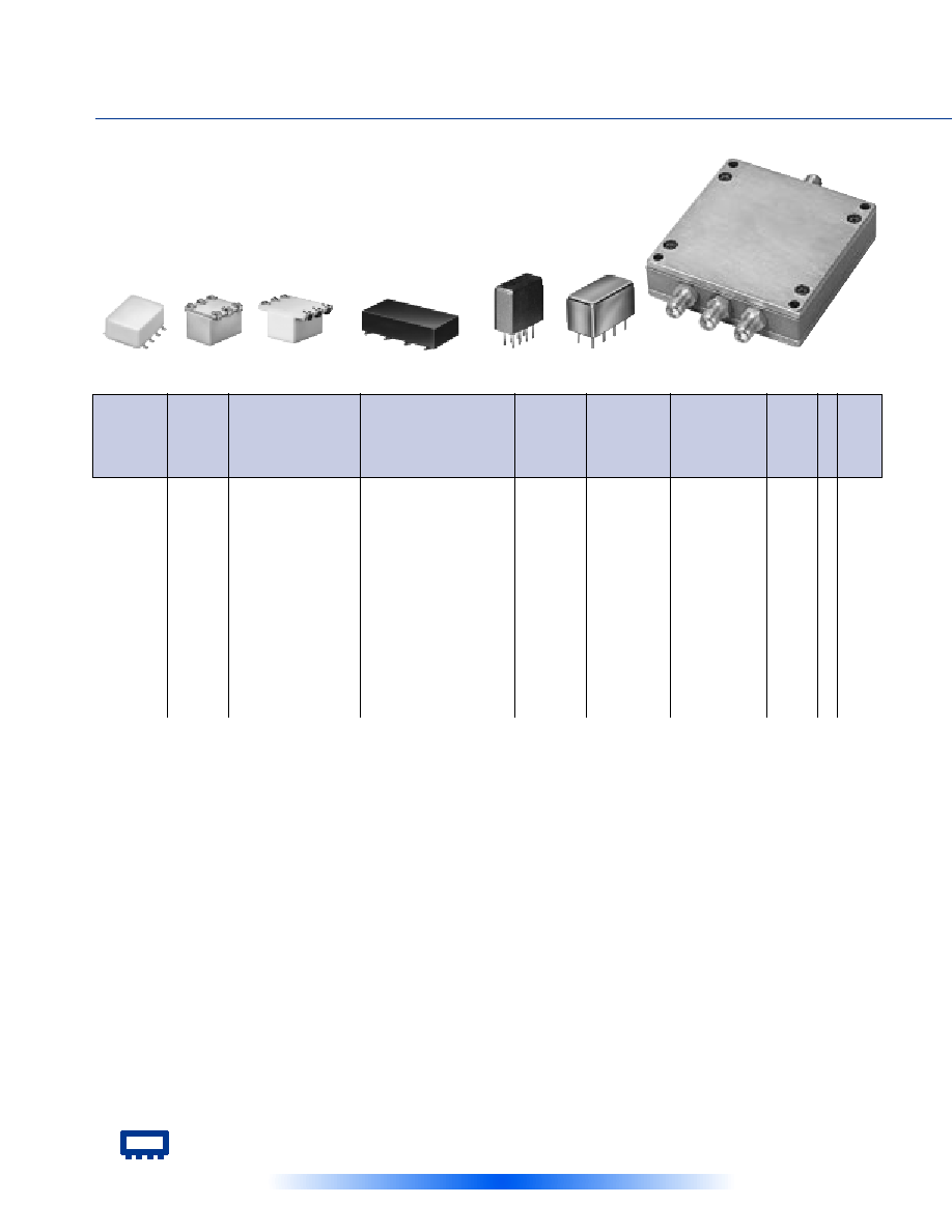
P
OWER
S
PLITTERS
/C
OMBINERS
3 W
AY
-0∞
10 kHz to 4.2 GHz
50&75
see suggested PCB layout: PL-063 for AD3PS-1
PL-097 for JPS-3 models
The Design Engineers Search Engine
Provides Actual Data Instantly
At:
http://www.minicircuits.com
In Stock... Immediate Delivery
For Custom Versions Of Standard Models
Consult Our Applications Dept.
Mini-Circuits
Æ
Æ
030328
131
**
ZFSC-3-1
1-500
30
20
30
20
25
18
0.4
0.75
0.5
0.9
0.8
1.2
2
3
4
0.2
0.3
0.4
J17
be
51.95
ZFSC-3-1W
2-750
30
20
30
20
25
18
0.4
0.75
0.5
1.0
1.0
1.6
3
5
7
0.2
0.3
0.5
J17
be
53.95
ZFSC-3-13
1-200
45
30
48
35
37
30
0.25 0.5
0.35 0.6
0.35 0.6
1
3
5
0.1
0.2
0.2
J17
be
51.95
ZFSC-3-4
1-1000
35
20
20
18
20
17
0.2
0.5
0.7
1.4
1.0
2.0
3
6
10
0.2
0.4
0.9
J17
be
59.95
n ZFSC-3-4-75
1-1000
34
22
27
17
23
15
0.2
0.5
0.4
1.2
1.2
2.0
3
6
10
0.5
0.7
0.9
J17
be
59.95
NEW
ZB3PD-2400W
700-2400
25
17
0.5
1.2
8
0.9
UU182
mw
99.95
ZA3PD-1
500-1000
20
14
20
14
20
14
0.3
0.6
0.3
0.6
0.3
0.6
--
--
--
0.4
0.4
0.4
CC51
be
89.95
ZA3PD-1.5
750-1500
20
14
20
14
20
14
0.3
0.7
0.3
0.7
0.3
0.7
--
--
--
0.4
0.4
0.4
CC51
be
89.95
ZA3PD-2
1000-2000
20
15
20
15
20
15
0.3
0.6
0.3
0.6
0.3
0.6
--
--
--
0.3
0.3
0.3
CC51
be
89.95
ZA3PD-4
2000-4200
18
14
18
14
18
14
0.7
1.0
0.7
1.0
0.7
1.0
--
--
--
0.9
0.9
0.9
CC51
be
89.95
ZCSC-3-R3
2-300
32
28
31
28
32
22
0.3
0.8
0.4
1.0
0.8
1.2
1
2
3
0.1
0.3
0.3
UU233
be
43.95
ZMSC-3-1
1-200
45
35
40
25
40
25
0.3
0.5
0.4
0.7
0.6
1
1
2
4
0.15
0.2
0.3
P26
be
57.95
ZSC-3-1
1-200
45
30
40
25
40
25
0.3
0.5
0.4
0.7
0.6
1.0
1
2
4
0.15
0.2
0.3
P25
be
51.95
< ZSC-3-2*
0.01-30
35
30
40
25
30
25
0.25 0.45
0.15 0.45
0.45 0.75
1
2
4
0.2
0.3
0.4
P25
be
61.95
n ZSC-3-1-75
1-200
35
30
35
25
35
25
0.6
1.0
0.4
0.7
0.6
1.0
2
3
4
0.15
0.2
0.3
P25
be
52.95
L = low range [f
L
to 10 f
L
]
M = mid range [10 f
L
to f
U
/2]
U = upper range [f
U
/2 to f
U
]
pin and coaxial connections
see case style outline drawings
PORT
bb
bc
bd
be
gt
hc
jg
jq
ma
mw
SUM PORT
6
1
6
S
6
6
1
1
1
S
PORT 1
1
5
1
1
1
1
6
5
8
1
PORT 2
2
7
2
2
2
3
4
6
5
2
PORT 3
5
8
5
3
3
4
3
2
4
4
NOT USED
--
--
--
--
--
--
--
--
--
3
GND EXT.
3,4,7,8
2,3,4,6
3,4,7,8
--
4,5
2,5
2,5
3,4,7,8
2,3,6,7
--
CASE GND
3,4,7,8
2,3,4,6
--
--
--
--
--
3,4,7,8
--
--
DEMO BOARD
--
--
--
--
--
--
--
TB-211
TB-83
--
ZCSC-3
ZA3PD
ZFSC-3
MIL-P-23971/15, NSN GUIDE
MCL NO.
NSN
PSC-3-1
6625-01-015-6027
PSC-3-1W
5985-01-295-5898
PSC-3-13
6625-01-249-8011
ZA3PD-2
5895-01-357-3919
ZFSC-3-1(SMA)
5895-01-361-8520
ZFSC-3-1
6625-01-235-6873
ZFSC-3-13
5895-01-335-1824
ZFSC-3-13(SMA)
5985-01-409-0884
ZFSC-3-4(SMA)
6625-01-333-1126
ZFSC-3-4(BNC)
6625-01-454-7617
ZMSC-3-1B(SMA)
6625-01-170-0102
ZSC-3-1
6625-01-327-4755
ZSC-3-1B(BNC)
6625-01-008-9566
ZSC-3-1BR
5985-01-462-0144
ZSC-3-2BR
5985-01-315-2870
ZSC-3-2B(BNC)
5820-01-120-9320
ISOLATION
dB
INSERTION LOSS, dB
Above 4.8dB
PHASE
UNBALANCE
Degrees
f
L
-f
U
M
J
J
J
J
J
Max.
L
Max.
U
Max.
AMPLITUDE
UNBALANCE
dB
U
Max.
M
J
J
J
J
J
Max.
L
Max.
FREQ.
RANGE
MHz
MODEL
NO.
M
J
J
J
J
J
Typ. Min.
L
Typ. Min.
U
Typ. Min.
L
Typ. Max.
M
J
J
J
J
J
Typ. Max.
U
Typ. Max.
C
O
N
N
E
C
T
I
O
N
CASE
STYLE
Qty.
(1-9)
PRICE
$
Note B
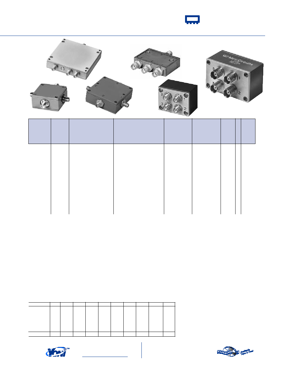
ZMSC-3
Surface Mount
t
, Plug-In & Coaxial
ZB3PD
ZSC-3