
+Vo
PFM
Isolation
Ref.Amp
+Vin
-Vin
-Vo
On/Off
Block Diagram
Wide Range
2:1
Low Cost
$
Low Profile
Remote on/off
I/O Isolation
1000
VDC
Low Noise
Minmax's MCW1000-Series power modules are low-profile dc-dc
converters that operate over input voltage ranges of 4.5-9VDC,
9-18VDC, 18-36VDC and 36-75VDC which provide precisely regulated
single output voltages of 3.3V, 5V and 12VDC.
The -40] to +85] operating temperature range makes it ideal for
data communication equipments, mobile battery driven equipments,
distributed power systems, telecommunication equipments, mixed
analog/digital subsystems, process/machine control equipments,
computer peripheral systems and industrial robot systems.
The modules have a maximum power rating of 2W and a typical
full-load efficiency of 81%, continuous short circuit, 30mV output ripple,
built-in filtering for both input and output minimize the need for external
filtering.
Internal SMD Construction
UL 94V-0 Package Material
Temperature Performance -40] to +85]
Low Ripple and Noise
Remote On/Off Control
Low Cost
2:1 Wide Input Range
MTBF > 1,000,000 Hours
1000VDC Isolation
High Efficiency up to 81%
Key Features
2W, Wide Input Range SIP, Single Output DC/DC Converters
MCW1000 Series
REV:0 2005/04
MINMAX
1
79
53
42
167
12
MCW1043
73
57
100
400
5
MCW1042
71
500
8
49
125
500
3.3
48
( 36 ~ 75 )
MCW1041
81
103
42
167
12
MCW1033
77
109
100
400
5
MCW1032
72
200
10
96
125
500
3.3
24
( 18 ~ 36 )
MCW1031
80
209
42
167
12
MCW1023
77
217
100
400
5
MCW1022
73
300
20
184
125
500
3.3
12
( 9 ~ 18 )
MCW1021
75
534
42
167
12
MCW1013
73
548
100
400
5
MCW1012
70
400
40
471
125
500
3.3
5
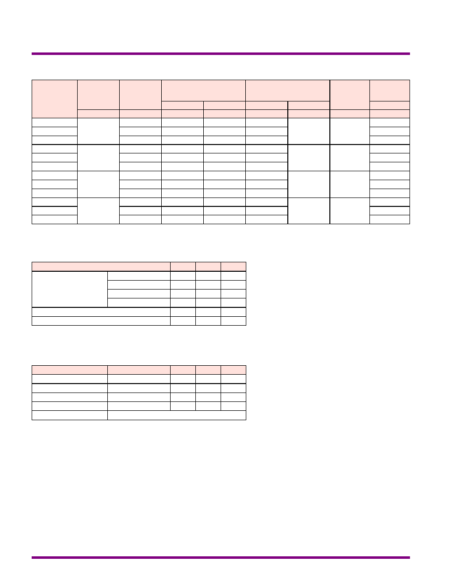
( 4.5 ~ 9 )
MCW1011
% (Typ.)
mA (Typ.)
mA (Typ.)
mA (Typ.)
mA
mA
VDC
VDC
@Max. Load
@No Load
@Max. Load
Min.
Max.
Efficiency
Reflected
Ripple
Current
Input Current
Output Current
Output
Voltage
Input
Voltage
Model
Number
Model Selection Guide
Free-Air Convection
Cooling
%
95
---
Humidity
]
+105
-55
Storage Temperature
]
+90
-40
Case
Operating Temperature
]
+85
-40
Ambient
Operating Temperature
Unit
Max.
Min.
Conditions
Parameter
Environmental Specifications
Exceeding the absolute maximum ratings of the unit could cause damage.
These are not continuous operating ratings.
mW
3500
---
Internal Power Dissipation
]
260
---
Lead Temperature (1.5mm from case for 10 Sec.)
VDC
100
-0.7
48VDC Input Models
VDC
50
-0.7
24VDC Input Models
VDC
25
-0.7
12VDC Input Models
VDC
15
-0.7
5VDC Input Models
Input Surge Voltage
( 1000 mS )
Unit
Max.
Min.
Parameter
Notes :
1. Specifications typical at Ta=+25], resistive load,
nominal input voltage, rated output current unless
otherwise noted.
2. Transient recovery time is measured to within 1%
error band for a step change in output load of 75%
to 100%.
3. Ripple & Noise measurement bandwidth is 0-20
MHz.
4. These power converters require a minimum
output loading to maintain specified regulation.
5. Operation under no-load conditions will not
damage these modules; however, they may not
meet all specifications listed.
6. All DC/DC converters should be externally fused at
the front end for protection.
7. Other input and output voltage may be available,
please contact factory.
8. Specifications subject to change without notice.
Absolute Maximum Ratings
MCW1000 Series
2
MINMAX
REV:0 2005/04
K Hours
---
---
1000
MIL-HDBK-217F @ 25], Ground Benign
MTBF
KHz
650
300
100
Switching Frequency
pF
120
65
---
100KHz,1V
Isolation Capacitance
M[
---
---
1000
500VDC
Isolation Resistance
VDC
---
---
1100
Flash Tested for 1 Second
Isolation Voltage Test
VDC
---
---
1000
60 Seconds
Isolation Voltage Rated
Unit
Max.
Typ.
Min.
Conditions
Parameter
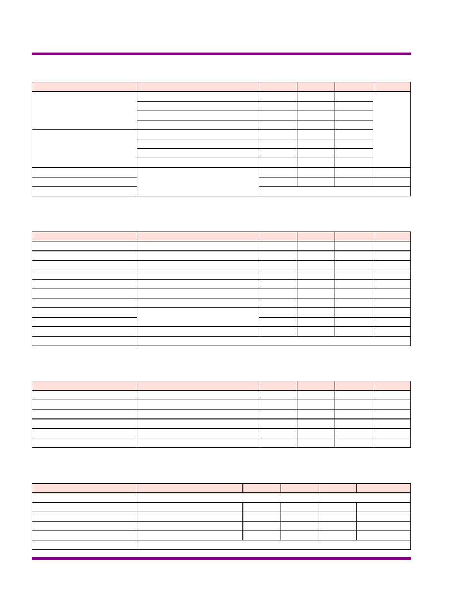
General Specifications
Continuous
Output Short Circuit
%/]
{0.02
{0.01
---
Temperature Coefficient
%
{5
{3
---
Transient Response Deviation
uS
300
100
---
25% Load Step Change
Transient Recovery Time
%
---
---
120
Over Power Protection
mV rms
15
---
---
Ripple & Noise (20MHz)
mV P-P
75
---
---
Over Line, Load & Temp.
Ripple & Noise (20MHz)
mV P-P
50
30
---
Ripple & Noise (20MHz)
%
{0.75
{0.5
---
Io=25% to 100%
Load Regulation
%
{0.5
{0.3
---
Vin=Min. to Max.
Line Regulation
%
{2
{1
---
Output Voltage Accuracy
Unit
Max.
Typ.
Min.
Conditions
Parameter
Output Specifications
Capacitor type
Input Filter
mW
1500
---
---
Short Circuit Input Power
A
1
---
---
All Models
Reverse Polarity Input Current
34
22
---
48V Input Models
17
11
---
24V Input Models
8.5
6.5
---
12V Input Models
4
3.5
---
5V Input Models
Under Voltage Shutdown
36
24
16
48V Input Models
18
12
8
24V Input Models
9
7
4.5
12V Input Models
VDC
4.5
4
3.5
5V Input Models
Start Voltage
Unit
Max.
Typ.
Min.
Model
Parameter
Input Specifications
Referenced to Negative Input
Control Common
mA
1
---
---
Vin-RC = 5.0V
Control Input Current ( off )
mA
-0.4
---
---
Vin-RC = 0V
Control Input Current ( on )
mA
0.2
0.1
---
Device Standby Input Current
VDC
15
---
2.7
Supply Off
Under 0.6 VDC or Open Circuit, drops down to 0VDC by 2mV/]
Supply On
Unit
Max.
Typ.
Min.
Conditions
Parameter
Remote On/Off Control
MCW1000 Series
REV:0 2005/04
MINMAX
3
uF
170
1000
2200
Maximum Capacitive Load
Unit
12V
5V
3.3V
Models by Vout
Capacitive Load
135mA Slow - Blow Type
350mA Slow - Blow Type
700mA Slow - Blow Type
1500mA Slow - Blow Type
48V Input Models
24V Input Models
12V Input Models
5V Input Models
Input Fuse Selection Guide
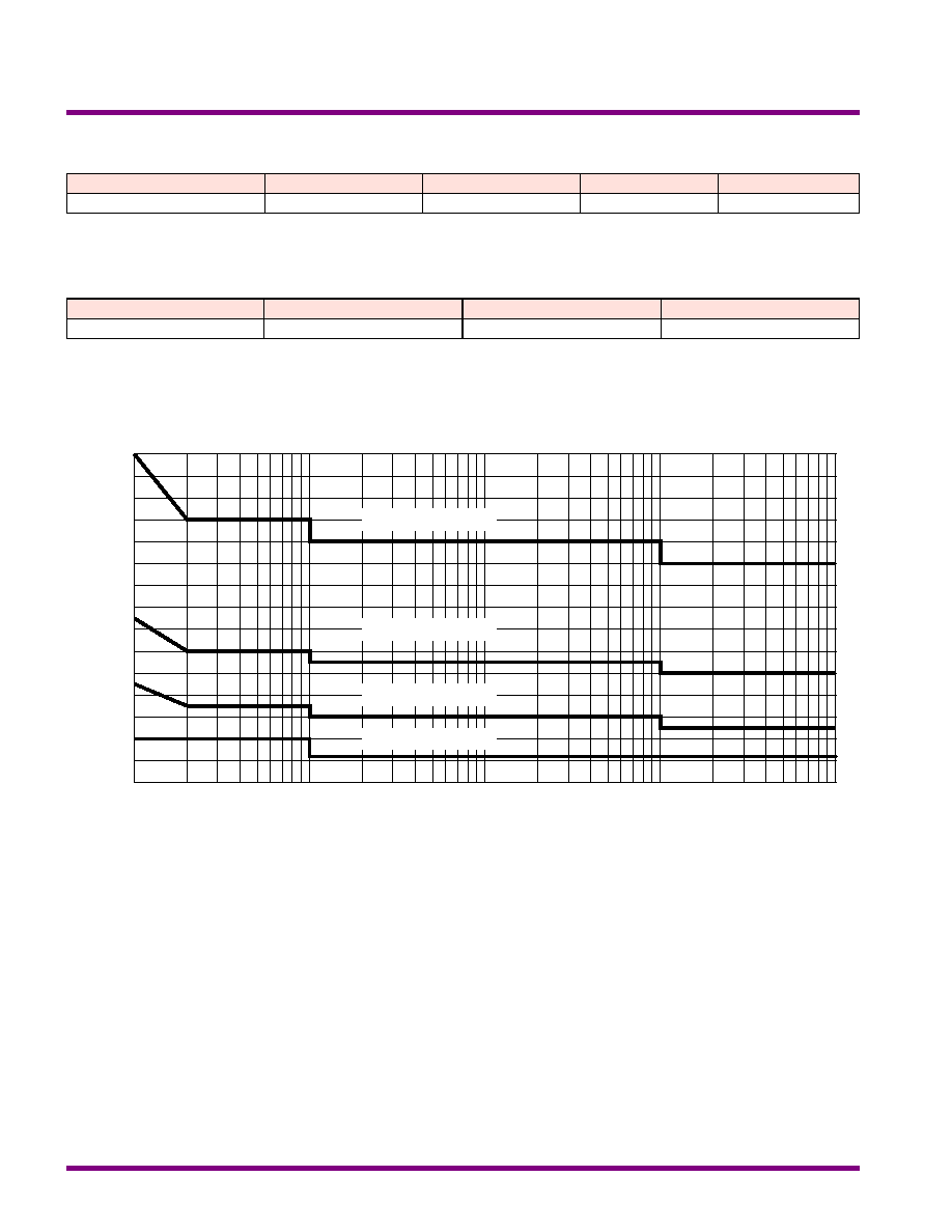
Input Voltage Transient Rating
MCW1000 Series
4
MINMAX
REV:0 2005/04
Vin ( VDC )
10uS
150
140
130
120
110
100
90
80
70
60
100uS
1mS
10mS
100mS
50
40
30
20
10
0
48VDC Input Models
24VDC Input Models
12VDC Input Models
5VDC Input Models
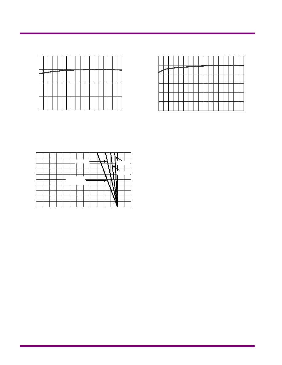
Derating Curve
]
Ambient Temperature
Output Power (%)
0
20
40
60
80
100
-40
50
60
80
100
110
90
70
400LFM
200LFM
100LFM
Natural
convection
Efficiency vs Output Load
Efficiency vs Input Voltage
30
40
50
60
70
80
90
Load Current(%)
Efficiency(%)
100
60
40
20
10
80
50
60
70
80
90
Efficiency (%)
Input Voltage (V)
Nom
Low
High
MCW1000 Series
REV:0 2005/04
MINMAX
5