PRODUCT INFORMATION
Europe: Tel (46) 8 58 02 45 00
Fax (46) 8 58 02 01 10
Tel (44) 1291 436180
Fax (44) 1291 436771
America: Tel 1-800-96MITEL Fax (613) 592-6909
Asia:
Tel (65) 293 5312
Fax (65) 293 8527
840
nm
1A239
High-Performance LED
Datacom, General Purpose
11960.11 & .12 1996-01-23
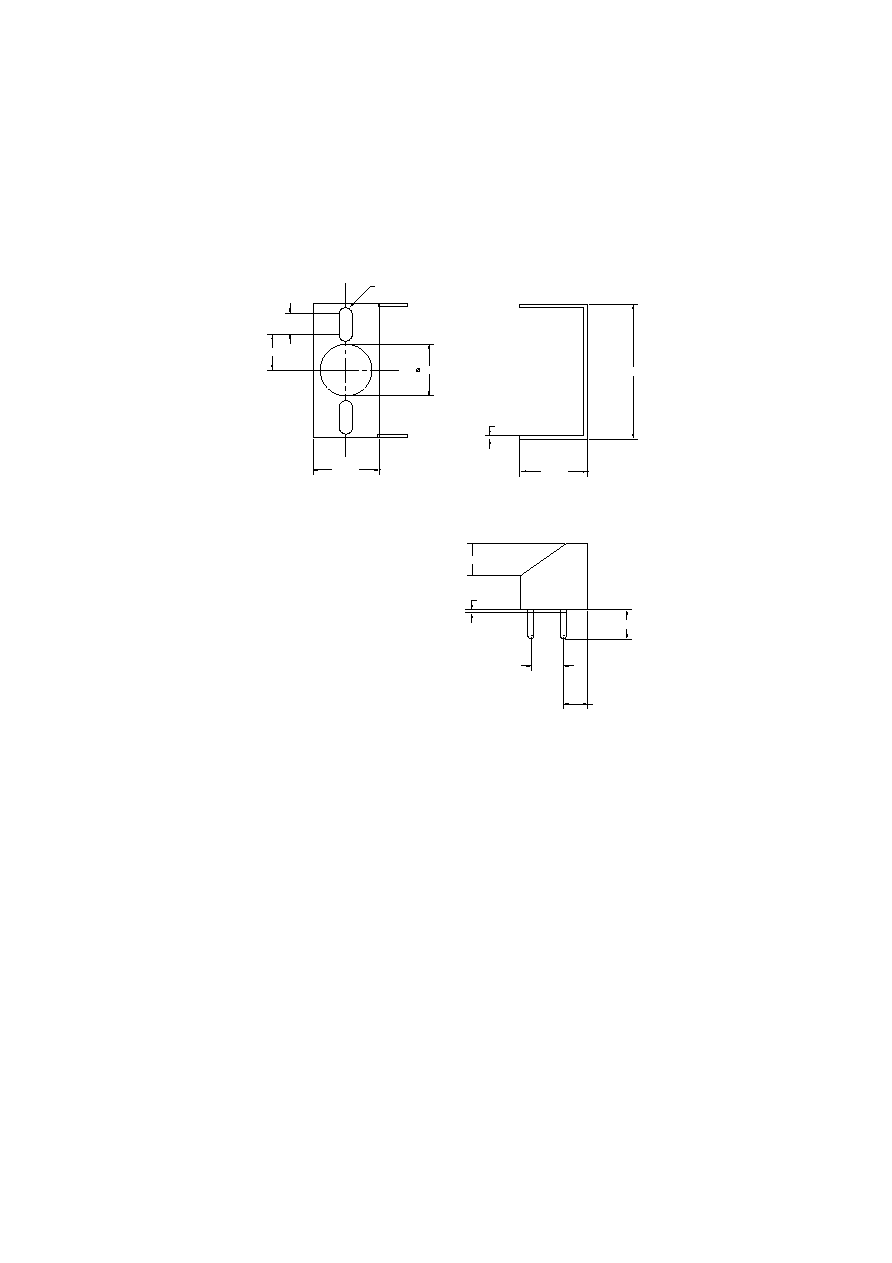
0.6
14
ÿ1.5
ÿ4.7
3.7
0.4
5.4
2.5
CASE
ANODE
CATHODE
BOTTOM VIEW
The diode chip is isolated from the case.
TO-46 Package With Lens
All dimensions in mm
This device is designed for Ethernet
and general applications and offers an
excellent price/performance ratio for
cost-effective solutions. Since it oper-
ates at low drive current, it generates
minimal heat -- reducing cooling
requirements in systems employing
large numbers of LEDs.
Thermal Characteristics
Fiber:
50/125 m
Graded
Index
NA=0.20
Optical and Electrical Characteristics
(25∞ C Case Temperature)
Absolute Maximum Ratings
Note 1: Measured at the exit of 100 meters of fiber.
Note 2: 1A239A version with Fiber-Coupled Power > 80 W available on request.
PARAMETER
SYMBOL
MIN.
TYP.
MAX.
UNIT
Thermal Resistance - Infinite Heat Sink
Rthjc
300
C/W
Thermal Resistance - No Heat Sink
Rthja
600
C/W
Temperature Coefficient - Optical Power
dP/dTj
-0.4
%/ C
Temperature Coefficient -Wavelength
d /dTj
0.3
nm/ C
PARAMETER
SYMBOL
LIMIT
Storage Temperature
Tstg
-55 to +125 C
Operating Temperature
(derating: Fig.4)
Top
-55 to +125 C
Electrical Power Dissipation
(derating: Fig.4)
Ptot
130 mW
Continuous Forward Current
(f 10 kHz)
I
F
60 mA
Peak Forward Current
(duty cycle 50%, f 1 MHz)
I
FRM
100 mA
Reverse Voltage
V
R
1.5 V
Soldering Temperature
(2mm from the case for 10 sec)
Tsld
260 C
PARAMETER
SYMBOL
MIN.
TYP.
MAX.
UNIT
TEST CONDITION
Fiber-Coupled Power
Pfiber
50
90
W
I
F
=50 mA
(Fig.1, 2,& 3) (Table 1)
(Note 1,2)
Rise and Fall Time
tr,tf
7
10
ns
I
F
=50 mA
(10-90%)
(no bias)
Bandwidth
fc
50
MHz
I
F
=50 mA
(3dBel)
Peak Wavelength
p
820
840
860
nm
I
F
=50 mA
Spectral Width
(FWHM)
50
nm
I
F
=50 mA
Forward Voltage
(Fig.5)
V
F
1.8
2.0
V
I
F
=50 mA
Reverse Current
I
R
20
A
V
R
=1V
Capacitance
C
250
pF
V
R
= 0V, f=1 MHz
840
nm
1A239
High-Performance LED
0
20
40
60
80
100
%
0.5
1.0
1.5
2.0
2.5 3.0 mm
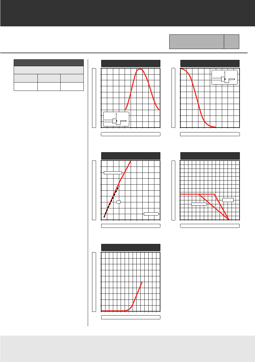
z - AXIAL DISPLACEMENT OF FIBER
RELA
TIVE FIBER-COUPLED PO
WER
r
r = opt.
ÿc = 50 µm
z
FIGURE 1
0
20
40
60
80
100
%
0
20
40
60
80
100 µm
r - RADIAL DISPLACEMENT OF FIBER
RELA
TIVE FIBER-COUPLED PO
WER
r
z = opt.
ÿc = 50 µm
z
FIGURE 2
0
20
40
60
80
100
%
0
40
80
120
160
200 mA
RELA
TIVE FIBER-COUPLED PO
WER
FORWARD CURRENT
50% DUTY CYCLE
DC
HEAT SINKED
FIGURE 3
FORWARD VOLTAGE
FORWARD CURRENT
mA
200
100
0
0
1
2
3
V
FIGURE 5
mW
300
200
100
0
0
50
100
150°C
MAX. ELECTRICAL POWER DISSIPATION
NO HEAT SINK
OPERATING TEMPERATURE
FIGURE 4
INFINITE
HEAT SINK
Core Diameter/Cladding Diameter
Numerical Aperture
50/125 m
62/125 m
100/140 m
0.20
0.275
0.29
Table 1
Typical Fiber-Coupled Power
90 W
150 W
250 W

PRODUCT INFORMATION
Europe: Tel (46) 8 58 02 45 00
Fax (46) 8 58 02 01 10
Tel (44) 1291 436180
Fax (44) 1291 436771
America: Tel 1-800-96MITEL Fax (613) 592-6909
Asia:
Tel (65) 293 5312
Fax (65) 293 8527
103326 1994-09-20
ST-2A
Package
Emitter or Detector in ST
Æ
Package
Mitel emitters and detectors can be
provided in this low-profile ST
Æ
package. The device is electrically
isolated from the ST
Æ
receptacle to
facilitate electrical connection. And
optimum fiber-coupled power or
responsivity is ensured by active
alignment against the fiber.
Mechanical Outline of Diode in ST-2A Housing
(ST is a registered trademark of AT&T)
All Dimensions in mm
*
The fiber-coupled power/responsivity is guaranteed to meet the LED/PIN data sheet - provided a ferrule meeting this specification is used.
Absolute Maximum Ratings
Thermal Characteristics
Note 2: Add Rthjc for emitter or detector to estimate the total thermal resistance.
Note 1: Temperature range can be extended to -55∞ to +125∞C on request.
12.7
MARKING SIDE
SLOT SIDE
9.5
7.89
2-56 UNC - 2B
max.0.5
min.12
20.1
3.9
5.4
7.6
3/8"-32 UNEF
0.006
FIBER
END
ÿ2.5
ÿ2.502
+0.01
0
+0
-0.004
MATING FERRULE
*
(not included)
PARAMETER
SYMBOL
LIMIT
Operating & Storage Temperature
Tstg, Top
-40 to + 85 C
ST-2A (Note 1)
PARAMETER
SYMBOL
MIN.
TYP.
MAX.
UNIT
Thermal Resistance - Infinite Heat Sink
Rthcc
40
C/W
(Note 2)
Thermal Resistance - No Heat Sink
Rthca
200
C/W
(Note 2)
Thermal Resistance - On PC Board
Rthca
80
C/W
(Note 2)