 | –≠–ª–µ–∫—Ç—Ä–æ–Ω–Ω—ã–π –∫–æ–º–ø–æ–Ω–µ–Ω—Ç: MF431ST | –°–∫–∞—á–∞—Ç—å:  PDF PDF  ZIP ZIP |
14
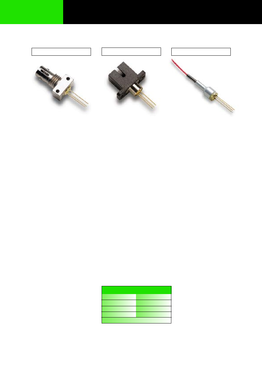
Description
This family of PIN Photodiodes is designed for Datacom, Telecom
and General purpose applications. Their unique design combines high
bandwidth with high responsivity for single-mode as well as multimode
fibers up to 62.5µm core diameter. The MF432 PIN Photodiode is
available in ST, SC, or Pigtail package.
Specially-designed connectors and clips for PC board assembly
are included in deliveries of MF432 in SC and Pigtail configurations.
The MF431 LED is the recommended transmitter for these PIN
photodiodes.
ST Assembly
SC Assembly
Pigtail Assembly
MF432 ST
MF432 SC
MF432 Pigtail
ST Applications
∑
FDDI
∑
ESCON
∑
ATM-SDH/SONET 155,
622 and 2488Mbps
∑
FITL - Fiber In The Loop
∑
FTTH/FTTC - Fiber To
The Home/Curb
∑
Intra-Office
Telecommunications
∑
General Purpose
Pigtail Applications
∑
ATM-SDH/SONET 155,
622 and 2488Mbps
∑
FITL - Fiber In The Loop
∑
FTTH/FTTC - Fiber To
The Home/Curb
SC Applications
∑
FDDI
∑
ESCON
∑
ATM-SDH/SONET 155,
622 and 2488Mbps
∑
FITL - Fiber In The Loop
∑
FTTH/FTTC - Fiber To
The Home/Curb
∑
Intra-Office
Telecommunications
∑
General Purpose
13325.11 1997-04-01
13326.11 1997-04-01
13327.11 1997-04-01
Features-All MF432 Devices
∑
1300 and 1550nm PIN
Photodiode
∑
2.5GHz Bandwidth
∑
Designed for Single-Mode
and Multi-Mode Fiber
∑
Aligned in ST
Æ
, SC
Receptacle or with a
Single-Mode Fiber Pigtail
∑
Tested to Bellcore
TA-NWT-000983
∑
High Return Loss in Pigtail
Configuration
MF432
Datacom, Telecom, General Purpose PIN Photodiodes
Ordering Information
PART #
RECEPTACLE
MF431 ST
ST
MF 432 SC
SC
MF 432 Pigtail
Pigtail
-40∞C to +85∞C

15
ST
SC
Pigtail
FIBER
EMITTER
BOTTOM VIEW
ANODE
CASE
CATHODE
MF432
PIN
Datacom, Telecom, General Purpose PIN Photodiodes
MF432
MF432 Functional Diagram For ST, SC and Pigtail

16
Optical & Electrical Characteristics (Case Temperature -25 to +70∞C)
Units
A/W
GHz
pF
nA
Test Conditions
=1300nm (Note 1)
=1550nm V
R
=5V
V
R
=5V R
L
=50
(Note 1)
V
R
=5V f=1MHz
T
Case
=25∞C
T
Case
=70∞C
V
R
=5V
(Note 2)
Max.
1.2
3
50
Min.
0.7
0.8
2.5
40
Typ.
0.8
1.0
0.8
55
Symbol
R
f
c
C
I
d
RL
Parameter
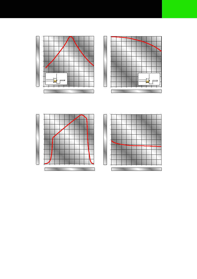
Responsivity (Fig 1, 2, 3)
Bandwidth
Capacitance (Fig 4)
Dark Current
Return Loss
Note 1: Data for 10/125µm single-mode fiber (NA=0.11) to 62.5/125µm graded index fiber (NA=0.275).
Note 2: With 10/125µm single-mode fiber pigtail (NA:0.11).
Absolute Maximum Ratings*
Units
∞C
∞C
V
∞C
Max.
+85
+85
20
260
Min.
-40
-40
Symbol
T
stg
T
op
V
R
T
sld
Parameter
Storage Temperature
Operating Temperature
Reverse Voltage
Soldering Temperature (Note 1)
Thermal Characteristics
*Exceeding these values may cause permanent damage. Functional operation under these conditions is not implied.
Note 1: 2mm from the case for 10s.
Units
%/ ∞C
Max.
Min.
Typ.
5
Symbol
dI
d
/dT
j
Parameter
Temperature Coefficient - Dark Current
MF432
Datacom, Telecom, General Purpose PIN Photodiodes
17
0
2.0
pF
0
5
10 V
REVERSE VOLTAGE
CAP
A
CIT
ANCE
0
20
40
60
80
100
%
0
20
40
60
80
120
µ
m
r
z = opt.
ÿc = 62.5
µ
m
z
800
1000
1800
nm
0
100
%
1300
1500
0
20
40
60
80
100
%
0.5
1.0
1.5
2.0
2.5 3.0
mm
r
r = opt.
ÿc = 62.5
µ
m
z
900
1100 1200
1400
1600 1700
50
RELA
TIVE RESPONSIVITY
r - RADIAL DISPLACEMENT OF FIBER
RELA
TIVE RESPONSIVITY
z - AXIAL DISPLACEMENT OF FIBER
RELATIVE RESPONSIVITY
1.0
WAVELENGTH
Figure 1
Figure 2
Figure 3
Figure 4
Datacom, Telecom, General Purpose PIN Photodiodes
MF432
18
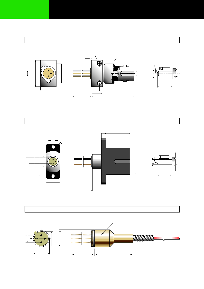
ÿ 6
0.4
2.5
5.4
min.12
MARKING
13
ÿ6.00
Fiber length 1m
ÿ2.3
ÿ7
.5
0.4
MARKING / SLOT SIDE
22
2.5
5.4
8.9
1.4 x 4
18
min. 12
12
2.5
7.95
0.006
FIBER
END
ÿ2.5
+0
-0.004
RECOMMENDED FERRULE
(not included)
13
18
12.7
MARKING SIDE
SLOT SIDE
9.5
0.4
7.89
2-56 UNC - 2B
max.0.5
min.12
20.1
3.9
5.4
7.6
3/8"-32 UNEF
0.006
FIBER
END
ÿ2.5
ÿ2.502
+0.01
0
+0
-0.004
RECOMMENDED
FERRULE
(not included)
5.4
2.5
Note: The PIN chip is isolated from the case. All dimensions in mm.
MF432
Datacom, Telecom, General Purpose PIN Photodiodes
MF432 ST Mechanical Data
MF432 SC Mechanical Data
MF432 Pigtail Mechanical Data