The NWK954 is a fully integrated, unmanaged, 4-port Fast
Ethernet Repeater conforming to the IEEE 802.3 100BASE-TX
Standard. The device integrates the 802.3 Repeater functions
with four 100BASE-TX PHY modules, enabling direct connection
to the isolation transformers with no additional PHY components.
It has built-in LED drivers for display of port activity and
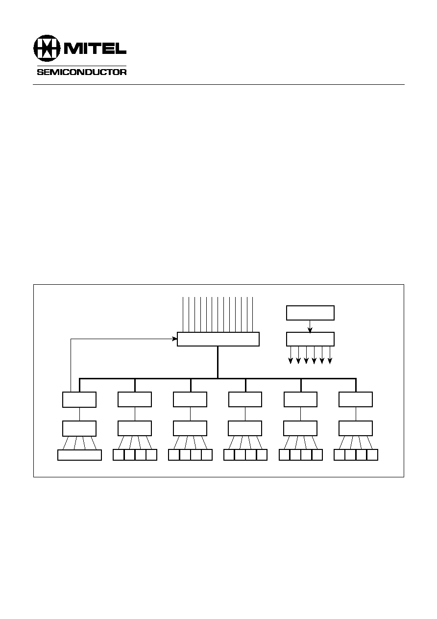
network utilization. There is a local expansion port which allows
up to six NWK954s to be cascaded to form a 24-port repeater
with no additional components.
With the addition of simple backplane driver/receivers, up to
eight 24-port repeaters can be stacked.
The NWK954 is supplied in a 128-pin PQFP and interfaces
to the twisted pair media through 1:1 isolation transformers.
QUAD RJ45
QUAD
MAGNETICS
NWK954
QUAD
MAGNETICS
NWK954
QUAD
MAGNETICS
NWK954
QUAD
MAGNETICS
NWK954
QUAD
MAGNETICS
NWK954
QUAD
MAGNETICS
NWK954
CLOCK DRIVERS
OSCILLATOR
BACKPLANE BUFFERS
BACKPLANE CONTROLS
LOCAL EXPANSION BUS
Fig. 1 System block diagram
FEATURES
s
Compliant with IEEE 802.3 100BASE-TX Repeater
Unit Specification
s
Incorporates four IEEE 802.3 Compliant 100BASE-TX
Ports
s
Local Expansion Port for Cascading to 24 Ports
s
Stackable Backplane for Expansion up to 192 Ports
s
Link/Activity LED and Receive Error LED for each Port
s
Collision LED
s
Five LED Network Utilization Display
s
Base Line Wander Correction
s
Power Saving on Unused Ports
s
Driven from a Single 25MHz Clock
s
Single 5V supply
s
Low Power CMOS Technology
s
128-pin PQFP package
ORDERING INFORMATION
NWK954D/CG/GH1N
NWK954
QUAD FAST ETHERNET REPEATER
PRELIMINARY INFORMATION
Supersedes January 1998 version, DS4842 - 1.1
DS4842-2.1 April 1998

NWK954
2
QUAD RJ45
QUAD
MAGNETICS
NWK954
QUAD
MAGNETICS
NWK954
QUAD
MAGNETICS
NWK954
QUAD
MAGNETICS
NWK954
QUAD
MAGNETICS
NWK954
QUAD
MAGNETICS
NWK954
CLOCK DRIVERS
OSCILLATOR
BACKPLANE BUFFERS
BACKPLANE CONTROLS
LOCAL EXPANSION BUS
Hub 0
Hub 1
Hub 2
Hub 3
Hub 4
Hub 5
Hub 6
Hub 7
Fig. 2 192-port stacked repeater

NWK954
3
1
2
3
4
5
6
7
8
9
10
11
12
13
14
15
16
17
18
19
20
21
22
23
24
25
26
27
28
29
30
31
32
96
95
94
93
92
91
90
89
88
87
86
85
84
83
82
81
80
79
78
77
76
75
74
73
72
71
70
69
68
67
66
65
33
34
35
36
37
38
39
40
41
42
43
44
45
46
47
48
49
50
51
52
53
54
55
56
57
58
59
60
51
62
63
64
IRD3
IRD2
DIGGND2
DIGVDD2
P0_RXLED_N
P0_ERLED_N
P1_RXLED_N
P1_ERLED_N
P2_RXLED_N
P2_ERLED_N
P3_RXLED_N
P3_ERLED_N
ACTLED_N4
ACTLED_N3
ACTLED_N2
ACTLED_N1
ACTLED_N0
DIGGND3
DIGVDD3
COLLED_N
BPDOE_N
BPDIE_N
BPCOLOE_N
BP
ACT
OUT_N
BPCOLIN_N
BP
ACTIN_N1
BP
ACTIN_N2
BP
ACTIN_N3
DIGGND4
DIGVDD4
IRD1
IRD0
IRD4
LACTOUT_N
DIGVDD1
DIGGND1
RESET_N
LACTIN_N1
LACTIN_N2
LACTIN_N3
LACTIN_N4
LACTIN_N5
TDC
TDIO
TA4
TA3
TA2
SUBVDD1
P0_RXGND3
P0_RXVDD3
P0_RXVDD2
P0_RXGND2
P0_RXGND1
P0_RXVDD1
P0_RXIN
P0_RXIP
P0_TXVDD3
P0_TXGND3
P0_TXREF
P0_TXGND2
P0_TXVDD2
P0_TXON
P0_TXOP
P0_GND1
BPCLK
BPCOL_N
DIGGND5
DIGVDD5
BPACTIN_N4
BPACTIN_N5
BPACTIN_N6
BPACTIN_N7
PSEN0
PSEN1
TXCLKIN
DIGGND6
DIGVDD6
VREFGND
VREFVDD
SUBVDD2
P3_RXGND3
P3_RXVDD3
P3_RXVDD2
P3_RXGND2
P3_RXGND1
P3�RXVDD1
P3_RXIN
P3_RXIP
P3_TXVDD3
P3_TXGND3
P3_TXREF
P3_TXGND2
P3_TXVDD2
P3_TXON
P3_TXOP
P3_TXGND1
128
127
126
125
124
123
122
121
120
11
9
11
8
11
7
11
6
11
5
11
4
11
3
11
2
11
1
11
0
109
108
107
106
105
104
103
102
101
100
99
98
97
P1_TXGND1
P1_TXOP
P1_TXON
P1_TXVDD2
P1_TXGND2
P1_TXREF
P1_TXGND3
P1_TXVDD3
P1_RXIP
P1_RXIN
P1_RXVDD1
P1_RXGND1
P1_RXGND2
P1_RXVDD2
P1_RXVDD3
P1_RXGND3
P2_RXGND3
P2_RXVDD3
P2_RXVDD2
P2_RXGND2
P2_RXGND1
P2_RXVDD1
P2_RXIN
P2_RXIP
P2_TXVDD3
P2_TXGND3
P2_TXREF
P2_TXGND2
P2_TXVDD2
P2_TXON
P2_TXOP
P2_TXGND1
NWK954
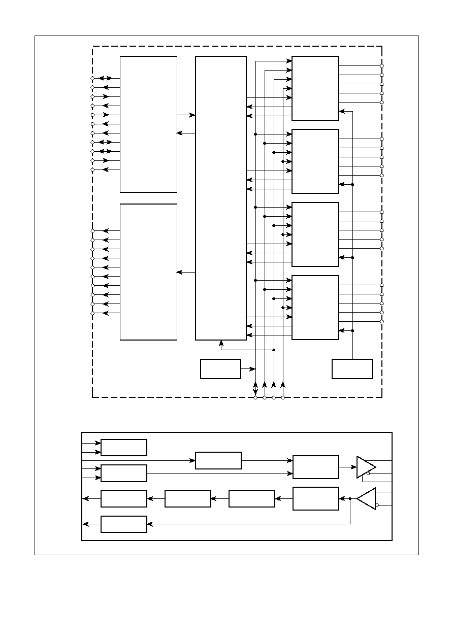
Fig. 3 Pin connections � top view
FUNCTIONAL DESCRIPTION
Overvlew
The NWK954 is a mixed-signal CMOS device which
integrates all of the functions required for an unmanaged 4-
port 100BASE TX repeater as defined in the IEEE 802.3
Standard. The device incorporates all of the necessary
100BASE-TX PHY functions to allow direct interfacing to a
quad 1:1 magnetics module with a modest number of external
passive components. The built-in expansion port allows
cascading of up to 6 NWK954s to build a 24-port repeater
with no additional components and also allows stacking of
up to eight 24-port repeaters with the addition of simple
backplane driver/receiver components. The operating status
of the device is indicated on 14 outputs designed to directly
drive LEDs. This high level of integration combined with low
power consumption and low pin count offers an efficient and
low cost solution for Fast Ethernet unmanaged repeater design.
Compliance with Standards
The NWK954 is designed for compliance with the IEEE 802.3
Standard, Clause 24 (100BASE-X PCS and PMA), Clause 25
(100BASE-TX PMD) and Clause 27 (Repeater for 100Mb/s
Baseband Networks). Clause 25 references the FDDI twisted
pair PMD Standard, henceforth referred to as TP-PMD.
Compatibility With Other Devices
The NWK954 is designed to connect directly to 5 other
NWK954 devices using the expansion bus. The Expansion Port
is identical to that used on the NWK950 Repeater Controller.
The Expansion Port may be connected to a backplane through
external driver/receivers. The backplane specification is identical
to that used by the NWK950, so repeaters using the NWK950
may be stacked with repeaters using the NWK954.
GP128
NWK954
4
PORT 0
TRANSCEIVER
P0_TXOP
P0_TXON
P0_TXREF
P0_RXIP
P0_RXIN
PORT 1
TRANSCEIVER
P1_TXOP
P1_TXON
P1_TXREF
P1_RXIP
P1_RXIN
PORT 2
TRANSCEIVER
P2_TXOP
P2_TXON
P2_TXREF
P2_RXIP
P2_RXIN
PORT 3
TRANSCEIVER
P3_TXOP
P3_TXON
P3_TXREF
P3_RXIP
P3_RXIN
RESET_N
PSEN [1:0]
TXCLKIN
T
A
[4:2]
VOLTAGE
REFERENCE
REPEATER
CONTROLLER
POWER-ON
RESET
IRD [4:0]
LACTOUT_N
LACTIN_N
BPACTOUT_N
BPACTIN_ N [7:1]
BPDIE_N
BPDOE_N
BPCLK
BPCOL_N
BPCOLIN_N
BPCOLOE_N
EXPANSION
PORT
ACTLED_N [4:0]
COLLED_N
P0_RXLED_N
P0_ERLED_N
P1_RXLED_N
P1_ERLED_N
P2_RXLED_N
P2_ERLED_N
P3_RXLED_N
P3_ERLED_N
LED
DRIVERS
TRANSCEIVER
CONTROL
SCRAMBLER
DESCRAMBLER
LINE
MONITOR
SIPO AND
DECODER
CLOCK
RECOVERY
EQUALIZER
AND BLW
CORRECTION
PISO
AND
ENCODER
125MHz
SYNTHESIZER
RX SIGNAL
DETECT
TX DRIVER
Port [3:0] transceiver details
Fig. 4 NWK954 block diagram
NWK954
5
Basic Repeater Function
The Repeater Controller monitors activity on the 4 twisted
pair ports and on the Expansion Port. When a packet is received
on one of the twisted pair ports it is forwarded to the other 3
twisted pair ports and to the Expansion Port. When a packet is
received on the Expansion Port it is forwarded to all 4 twisted
pair ports. When receive activity is detected on 2 or more ports
the Repeater Controller will send the jam signal to all twisted
pair ports for the duration of all activity associated with the
collision event.
Jabber Protection
The Repeater Controller provides receive jabber protection
to ensure that the network is not disrupted by excessively long
data streams. If a received data stream exceeds 65,536 bit times
then the receiving port will be shutdown. In the shutdown state
data received on the faulty port is ignored and packets received
from other ports are not transmitted to the faulty port. A port will
recover from the shutdown state when the incoming data stream
ends or if the device is reset.
Auto-Partition Function
The auto-partition function prevents faulty behaviour on a
network segment from disrupting the entire network. The
Repeater Controller counts consecutive collisions on each port
and will partition a port that causes more than 60 consecutive
collisions. In the partitioned state, packets received on the faulty
port will be ignored but packets received from other ports will
continue to be transmitted to the faulty port. The port will recover
from the partitioned state when valid activity is detected on the
port or if the device is reset.
Carrier Integrity Monitor
The Repeater Controller detects false carrier events on all
ports. A false carrier is defined as receive activity that does not
commence with the correct start-of-packet sequence. When a
false carrier event is detected, the Repeater Controller will
transmit the jam signal on all ports for the duration of the false
carrier event provided it does not exceed 450-500 bit times.
After this time the port will be isolated and the jam signal will
cease. The NWK954 will also isolate a port that suffers 2
successive false carrier events. In the isolated state, packets
received from the faulty port are ignored and packets received
from other ports are not transmitted to the faulty port. A port will
recover from the isolated state when a valid inter-packet gap is
detected and is followed by either a valid packet exceeding 450-
500 bit times or by an idle sequence exceeding 33000 (
�
25%)
bit times.
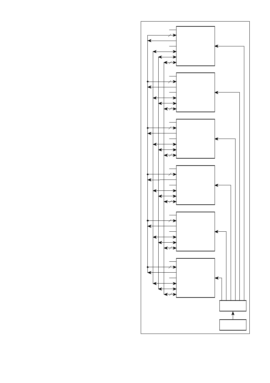
Expansion Port
The Expansion Port allows up to 6 NWK954s to be cascaded.
This allows a 24-port hub to be built with no additional external
components. The Expansion Port includes a 5-bit parallel
bidirectional data bus (IRD) which carries unscrambled symbol data
and a 25MHz sampling clock (BPCLK). Each NWK954 indicates
receive activity on any of its 4 twisted pair ports by asserting the
local activity output (LACTOUT_N). The LACTOUT_N signals from
each NWK954 connect to the local activity inputs (LACTIN_N) of all
the other cascaded NWK954s.
When a collision occurs between 2 twisted pair ports on an
NWK954, the event is communicated to other cascaded NWK954s
by asserting the collision signal (BPCOL_N). This instructs all
cascaded NWK954s to transmit the jam signal for the duration of
the collision event. BPCOL_N is also asserted when a collision occurs
between 2 twisted pair ports on different NWK954s.
Backplane
The Expansion Port allows hubs to be stacked via a backplane
bus. This requires the addition of some simple external driver/
receivers. The functional requirement for these components is
illustrated in Fig. 6. Contact Mitel for full details of recommended
components.
BPACTIN_ N [7:1]
LACTIN_N [5:1]
LACTOUT_N
BPCOLIN_N
BPCOL_N
BPCLK
IRD [4:0]
TXCLKIN
BPACTIN_ N [7:1]
LACTIN_N [5:1]
LACTOUT_N
BPCOLIN_N
BPCOL_N
BPCLK
IRD [4:0]
TXCLKIN
BPACTIN_ N [7:1]
LACTIN_N [5:1]
LACTOUT_N
BPCOLIN_N
BPCOL_N
BPCLK
IRD [4:0]
TXCLKIN
BPACTIN_ N [7:1]
LACTIN_N [5:1]
LACTOUT_N
BPCOLIN_N
BPCOL_N
BPCLK
IRD [4:0]
TXCLKIN
BPACTIN_ N [7:1]
LACTIN_N [5:1]
LACTOUT_N
BPCOLIN_N
BPCOL_N
BPCLK
IRD [4:0]
TXCLKIN
BPACTIN_ N [7:1]
LACTIN_N [5:1]
LACTOUT_N
BPCOLIN_N
BPCOL_N
BPCLK
IRD [4:0]
TXCLKIN
5
5
5
5
5
5
5
5
5
5
5
5
CLOCK
DRIVER
25MHz
OSCILLATOR
Fig. 5 Cascaded NWK954s