þÿ
TZ7-02-052 Rev.A(1/5)
29.Jan.2002
Approved
Charged
Approved
Customer
Approval
Specification for 10Gb/s
PIN PD and Preamp module
FU-321SPP-*7
A
B
C
D
x
Date
Approved
29.Jan.'02
T.Nambara
MITSUBISHI ELECTRIC.CORP.
TZ7-02-052 Rev.A(2/5)
29.Jan.2002
MITSUBISHI (OPTICAL DEVICES)
FU-321SPP-*7
PIN PD PREAMP MODULE FOR THE 1.31
µ
m WAVELENGTH RANGE
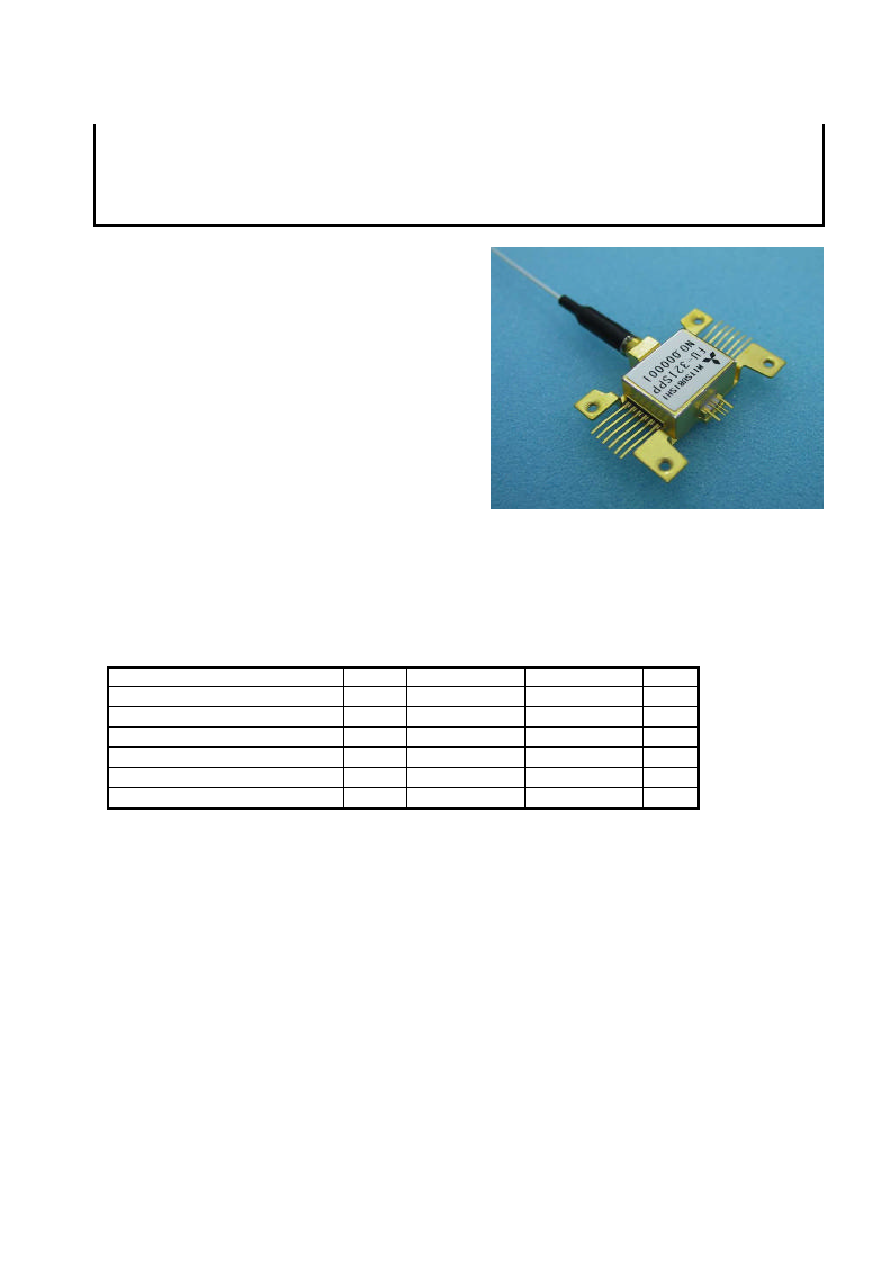
DESCRIPTION
FU-321SPP-*7 are PIN photodiode module with
preamplifier, designed for use in high-speed, long haul
optical communication systems.
The butterfly package contains an PIN photodiode
coupled with single-mode fiber pigtail and preamplifier.
FEATURES
·
High-sensitivity (-18dBm typ)
·
16pin butterfly package
·
Preamplifier supply voltage (-5.2V)
·
Photodiode bias voltage (+5V)
·
Trans impedance 1k
typical(RL=50
)
·
Trans impedance amp with limiting amp and
differential output (50
)
APPLICATION
10Gbps.optical receiver (OC-192, STM-64)
Extended reach datacom and telecom applications
Long haul optical communication systems
ABSOLUTE MAXIMUM RATINGS (Tc=25
°
C)
Parameter
Symbol
Conditions
Rating
Unit
PD Reverse voltage
Vpd
-
15
V
PD Reverse current (CW)
Ir
-
2
mA
PD Forward current (CW)
If
-
2
mA
Power supply voltage
Vss
-
-6.0~0.2
V
Operating case temperature
Tc
-
0~+70
°
C
Storage temperature
Tstg
-
-40~+85
°
C

TZ7-02-052 Rev.A(3/5)
29.Jan.2002
MITSUBISHI (OPTICAL DEVICES)
FU-321SPP-*7
PIN PD PREAMP MODULE FOR THE 1.31
µ
m WAVELENGTH RANGE
ELECTRICAL/OPTICAL CHARACTERISTICS
(Tc=25
°
C,
=1.3
µ
m,Vss=-5.2V ,Vpd=+5V unless otherwise noted)
Parameter
Symbol
Test Conditions
Limits
Unit
Min.
Typ.
Max.
Responsivity(Note 1)
R
CW
0.7
0.8
-
A/W
Transimpedance
Zt
AC,f=100MHz,RL=50
-
1
-
k
fc_High
AC,RL=50
-
8
-
GHz
Cutoff frequency(-3dB)
fc_Low
AC,RL=50
-
-
100
kHz
Average input equivalent
noise current density
in
AC,RL=50
,1MHz~7.5GHz
-
15
-
pA/
Hz
Output impedance
Zo
Single end (Note 2)
-
50
-
10MHz<f<8GHz
-
10
-
dB
Output return loss
S22
8GHz<f<12GHz
-
8
-
dB
Phase delay
Pd
200MHz<f<8GHz
-
40
-
ps
Sensitivity
Pr
-
-18
-15
Over load power
Po
AC,RL=50
,
NRZ, 10.7Gbps.,
PRBS=2
31
-1, BER=10
-12
(Note 1)
+1
-
-
dBm
Output voltage
Vo
AC,RL=50
,Pin=+1dBm
-
350
550
mVpp
Power supply voltage
Vss
-
-4.94
-5.2
-5.46
V
Power supply current
Iss
Vss=-5.2V
-
-
150
mA
Optical return loss
Prtn
-
27
-
-
dB
Note 1. Used post-amp bandwidth is 8GHz, Laser souse extinction ratio is 10dB.
Note 2. Please use output by AC coupling. Differential output.
OPTICAL FIBER SPECIFICATION
Parameter
Limits
Unit
Type
SM
-
Mode filed dia.
9.5
±
1
µ
m
Cladding dia.
125
±
2
µ
m
Jacket dia.
0.9 typ.
mm
Fiber length (L) (Note3)
1000~1200
mm
Note 3. See OUTLINE DIAGRAM
CONNECTOR OPTION
Type number
Connector type
Connector return loss
FU-321SPP-W7
SC connector
40dB(min.)
FU-321SPP-V7
FC/PC connector
40dB(min.)
FU-321SPP-7
With out connector
-
TZ7-02-052 Rev.A(4/5)
29.Jan.2002
MITSUBISHI (OPTICAL DEVICES)
FU-321SPP-*7
PIN PD PREAMP MODULE FOR THE 1.31
µ
m WAVELENGTH RANGE
DOCUMENTATION
Parameter
Symbol
Test conditions (Vpd=5V,Vss=-5.2V,Tc=25degC.)
Responsivity
R
CW
Cutoff frequency(-3dB)
fc_High
AC,RL=50
Sensitivity
Pr
AC,RL=50
,NRZ,10.7Gbps.,PRBS=2
31
-1, BER=10
-12
Power supply current
Iss
-
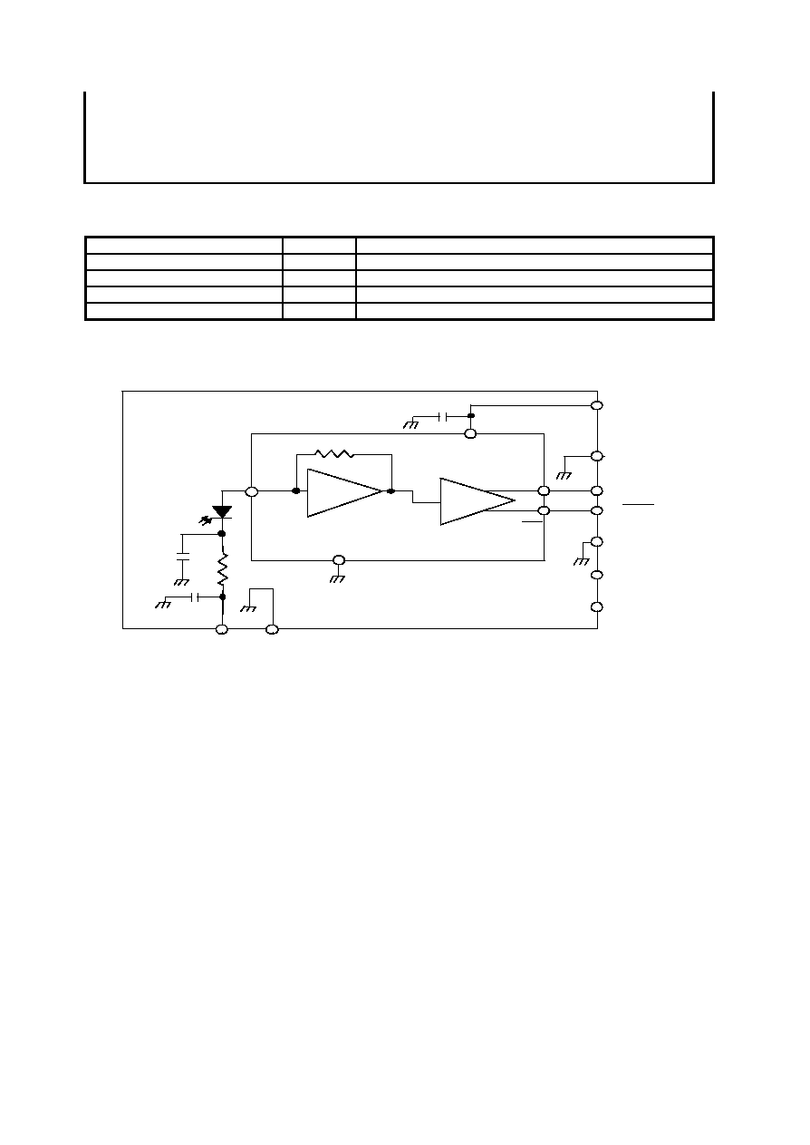
BLOCK DIAGRAM
T r a n s i m p e d a n c e a m p
P D
IN
OUT
OUT
1 V p d
2 G N D
1 0 G N D
7 G N D
11,12,13,
1 4 , 1 5,16
N C
4,5,6
N C
9 O U T
8 O U T
R f
Vss
3 Vss
GND
Limiting a m p
* Please use output by AC coupling.
*
*
TZ7-02-052 Rev.A(5/5)
29.Jan.2002
MITSUBISHI (OPTICAL DEVICES)
FU-321SPP-*7
PIN PD PREAMP MODULE FOR THE 1.31
µ
m WAVELENGTH RANGE
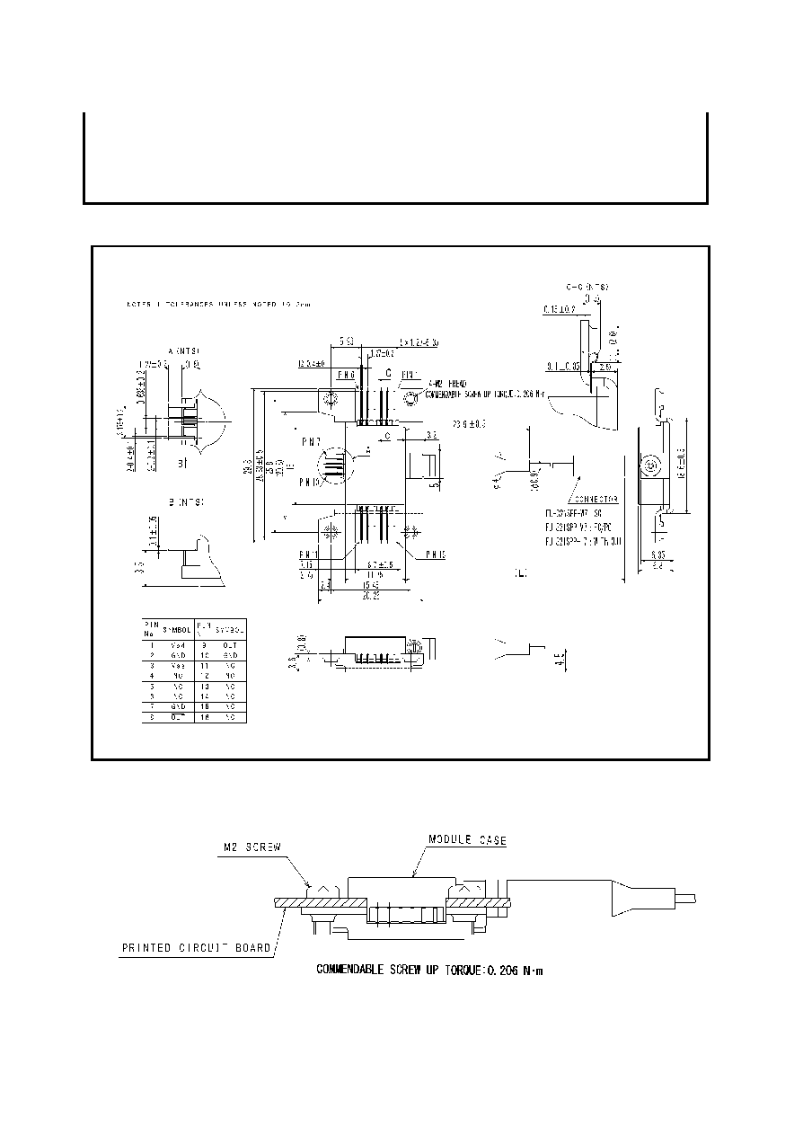
FU-321SPP-*7
OUTLINE DIAGRAM
(Unit : mm)
FU-321SPP-*7
SAMPLE MOUNTING
*1
*2
*3
*4