MITSUBISHI (OPTICAL DEVICES)
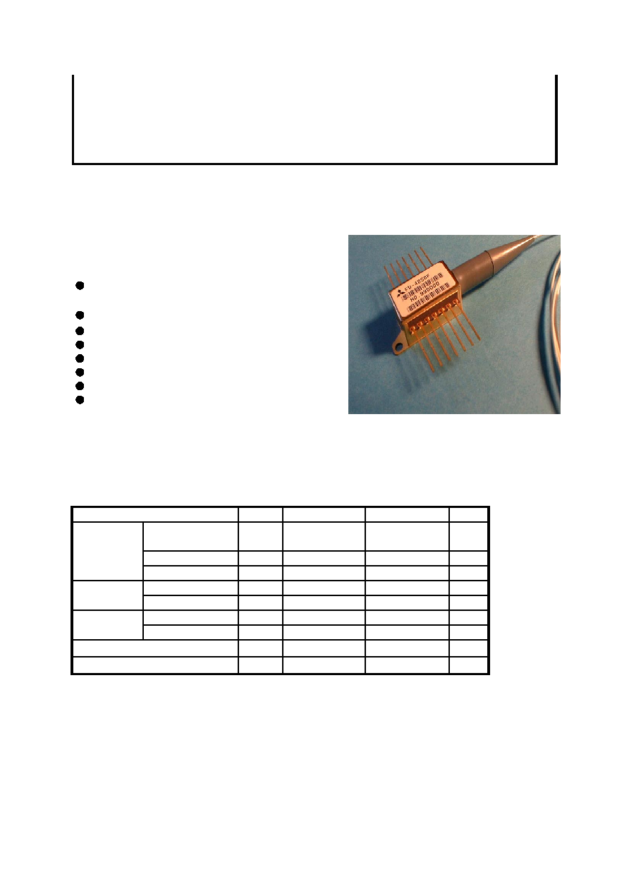
FU-48SDF-1
1.3
m
m DFB-LD MODULE WITH SINGLEMODE FIBER PIGTAIL
(BIAS CIRCUIT INTEGRATED, DIGITAL APPLICATION)
DESCRIPTION
Mod ule type FU-48SDF-1 is a 1.3
m
m DFB-LD mod ule
with single-mode optical fiber.
Th is mod ule is suitable to a light source for use in
2.5Gb/s digital optical communication systems.
FEATURES
Multi quantum wells (MQW) DFB Laser Diode
module
Input impedance is 25
W
Emission wavelength is in 1.3
m
m band
High-speed response
Built-in optical isolator
Built-in thermal electric cooler
Butterfly package
With photodiode for optical output monitor
APPLICATION
High speed transmission systems (~2.5Gb/s)
ABSOLUTE MAXIMUM RATINGS (Tld=25
°
C)
Parameter
Symbol
Conditions
Rating
Unit
Laser diode
Optical output power
from fiber end
Pf
CW
10
mW
Forword current
If
CW
150
mA
Reverse voltage
Vrl
-
2
V
Photodiode
Reverse voltage
Vrd
-
20
V
for monitoring
Forward current
Ifd
-
2
mA
Cooler
Cooler voltage
Vpe
-
2.4
V
(Note)
Cooler current
Ipe
-
1.2
A
Operating case temperature
Tc
-
-20~+65
°
C
Storage temperature
Tstg
-
-40~+70
°
C
No te. Even if the thermo-electric cooler (TEC) is operated within the rate d conditions, uncontrolled current loading
or operation without heatsink may easily damage the mod ule by exceeding the storage temperature range.
Th ermistor resistan ce should be properly mon itored by the feedback circuit during TE C operation to avoid
the catastrophic damage.
MITSUBISHI (OPTICAL DEVICES)
FU-48SDF-1
1.3
m
m DFB-LD MODULE WITH SINGLEMODE FIBER PIGTAIL
(BIAS CIRCUIT INTEGRATED, DIGITAL APPLICATION)
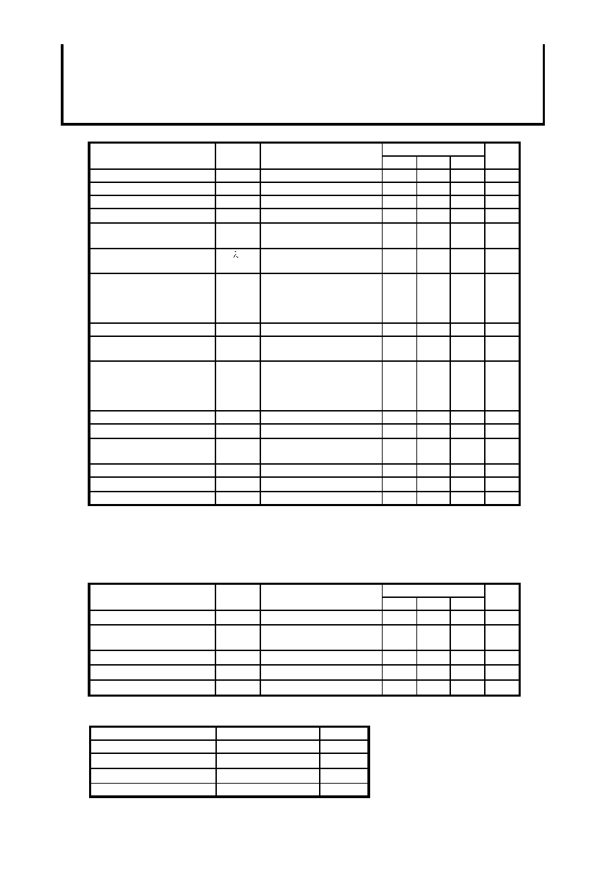
ELECTRICAL/OPTICAL CHARACTERISTICS (Tld=25
C,Tc=25
C, unless otherwise noted)
Parameter
Symbol
Test Conditions
Limits
Unit
Min.
Typ.
Max.
Threshold current
Ith
CW
-
15
40
mA
Operating current
Iop
CW
-
48
80
mA
Operating Voltage
Vop
CW,If=Iop (Note 1)
-
1.3
1.8
V
Input impedance
Zin
If=Iop
-
25
-
W
Optical output power from fib er
end
Pf
CW,If=Iop
4
6
-
mW
Light-emission central
wavelength
c
CW,If=Iop
1290
1310
1330
nm
Spectral width
(-20db full width)
Dl
2.5Gb/s NRZ
Mark ratio 50%
If_perk=Iop
Extinction ratio 8%
(Note 2)
-
0.4
-
nm
Side mode suppression ratio
Sr
CW,If=Iop
33
40
-
dB
Cutoff frequency
(-1,5dB optical)
fc
If=Iop
3.5
-
-
GHz
Rise and fall time
(10~90%)
tr,tf
2.5Gb/s NRZ
Mark ratio 50%
If_peak=Iop
Extinction ratio 8%
(Note 2)
-
-
150
ps
Relative intensity noise
Nr
CW,If=Iop
-
-155
-145
dB/Hz
Tracking error (Note 3)
Er
Tc=-20~+65
C,APC,ATC
-
0.3
-
dB
Differential efficiency
h
-
0.1
0.17
0.35
mW/
mA
Monitor current
Imon
CW,If=Iop,Vrd=5V
0.1
-
-
mA
Dark current (PD)
Id
Vrd=5V
-
0.1
1
m
A
Capacitance (PD)
Ct
Vrd=5V,f=1MHz
-
10
-
pF
Note 1. If: LD forward current
2. Optical return loss of the connectors should be greater than 40dB in order to get the specified
performance.
3. Er=MAX|10
¥
log(Pf(Tc)/Pf(25
C))|
THERMAL CHARACTERISTICS (Tld=25
C,Tc=-20~+65
C)
Parameter
Symbol
Test Conditions
Limits
Unit
Min.
Typ.
Max.
Thermistor resistance
Rth
Tld=25
C
9.5
10
10.5
k
W
B constant of thermistor
resistance
B
-
-
3950
-
K
Cooling capacity
D
T
Tc=65
C
40
-
-
C
Cooler current
Ipe
D
T=40
C
-
0.6
1
A
Cooler Voltage
Vpe
D
T=40
C
-
1.2
2
V
OPTICAL FIBER SPECIFICATION
Parameter
Limits
Unit
Type
SM
-
Mode filed dia.
9.5
±
1
m
m
Cladding dia.
125
±
2
m
m
Jacket dia.
0.9 typ.
mm
MITSUBISHI (OPTICAL DEVICES)
FU-48SDF-1
1.3
m
m DFB-LD MODULE WITH SINGLEMODE FIBER PIGTAIL
(BIAS CIRCUIT INTEGRATED, DIGITAL APPLICATION)
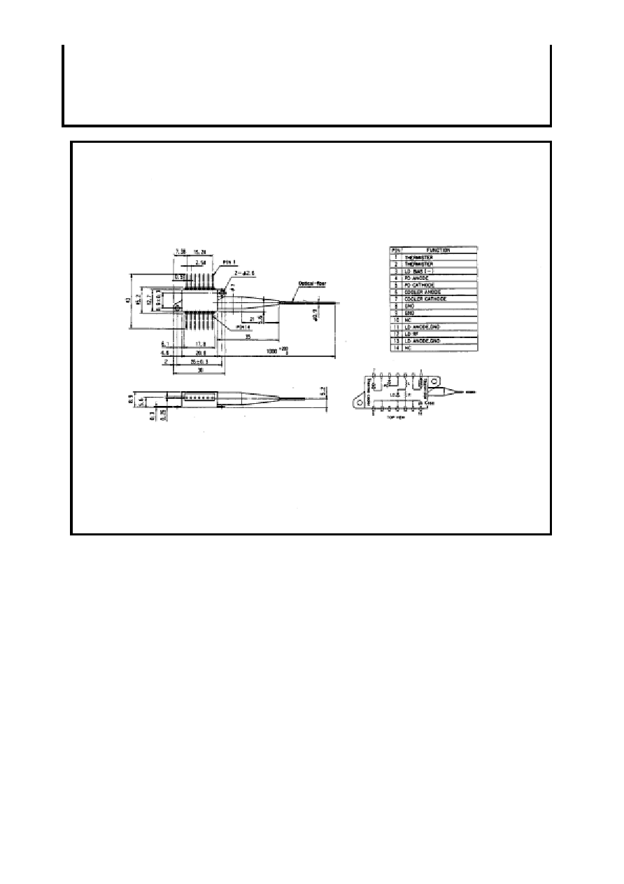
OUTLINE DIAGRAM
(Unit : mm)
FU-48SDF-1