
MITSUBISHI (OPTICAL DEVICES)
FU-653SEA-1Mx
1.55
µ
m EA MODULATOR INTEGLATED DFB-LD MODULE
(7 PIN PACKAGE WITH GPO CONNECTOR, 10GB/s DIGITAL APPLICATION)
DESCRIPTION
Module type FU-653SEA-1Mx is a 1.55
µ
m EA
modulator integrated DFB-LD module with single-
mode optical fiber.
This module is suitable to a light source for use in
10Gb/s digital optical communication systems.
FEATURES
l
Input impedance is 50
l
Integrated Electro-absorption Modulator
l
Distributed feed-back(DFB) Laser Diode
l
Emission wavelength is 1.55
µ
m band
l
Single mode optical fiber pigtail
l
Built-in optical isolator
l
Built-in thermoelectric cooler
l
7-pin Butterfly package with GPO connector
APPLICATION
STM-64, OC192 application
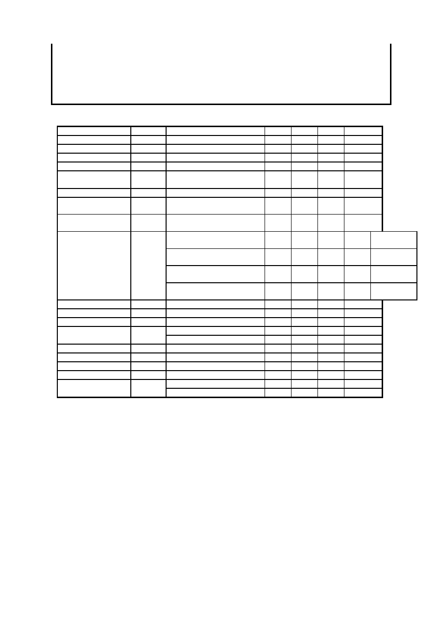
ABSOLUTE MAXIMUM RATINGS
Parameter
Symbol
Conditions
Rating
Unit
Optical output power
Pf
CW
6
mW
Forward current
If
CW
200
mA
Laser diode
Reverse voltage
Vrl
CW
2
V
Reverse voltage
Vrm
-
5
V
Modulator
Forward voltage
Vfm
-
1
V
Reverse voltage
Vrd
-
20
V
Photodiode for
monitoring
Forward current
Ifd
-
2
mA
Current
Ipe
-
1.5
A
Thermoelectric
cooler(Note1)
Voltage
Vpe
-
3
V
Operating case temperature
Tc
-
-20
70
∞
C
Storage temperature
Tstg
-
-40
85
∞
C
Note)
Even if the thermoelectric cooler (TEC) is operated within the rated conditions, uncontrolled current loading or
operation without heat sink may easily damage the module by exceeding the storage temperature range.
Thermistor resistance should be properly monitored by the feedback circuit during TEC operation to avoid the
catastrophic damage.
MITSUBISHI (OPTICAL DEVICES)
FU-653SEA-1Mx
1.55
µ
m EA MODULATOR INTEGLATED DFB-LD MODULE
(7 PIN PACKAGE WITH GPO CONNECTOR, 10GB/s DIGITAL APPLICATION)
ELECTRICAL/OPTICAL CHARACTERISTICS (Tld=Tset, Tc=25
∞
C unless otherwise noted)
Parameter
Symbol
Conditions(Note2)
Min.
Typ.
Max.
Unit
Threshold current
Ith
CW,Vm=0V
5
-
30
mA
Operating current
Iop
CW,Vm=0V
50
70
100
mA
Operating voltage
Vop
CW, If=Iop, Vm=0V
-
-
1.7
V
Input impedance
Zin
If=Iop
-
50
-
Optical output power
from fiber end
Pf
(Note 3,4)
-1
-
-
dBm
Wavelength
c
(Note 3,4)
1530
1550
1565
nm
Side mode
suppression ratio
Sr
(Note 3,4)
35
40
-
dB
Relative intensity
noise
RIN
CW, If=Iop, Vm=0V,10GHz
-
-
-135
dB/Hz
(Note 3,4), 130ps/nm
-
-
1.0
dB
FU-653SEA
-1M1
(Note 3,4), 800ps/nm
-
-
2.0
dB
FU-653SEA
-1M2
(Note 3,4), 36ps/nm
-
-
1.0
dB
FU-653SEA
-1M3
Dispersion penalty
Pp
(Note 3,4), 500ps/nm
-
-
2.0
dB
FU-653SEA
-1M4
Extinction ratio
Ex
(Note 3,4)
10
-
-
dB
Rise/fall time
tr/tf
(Note 3,4),20-80%
-
-
45
ps
Cutoff frequency
fc
If=Iop,Vm=-1V
10
-
-
GHz
If=Iop,Vm=-1V, f
5GHz
10
15
-
dB
RF return loss
S11
If=Iop,Vm=-1V, f
10GHz
5
7
-
dB
Tracking error
Er
If=Iop,Tc=-20
70
∞
C, Note 5
-
0.3
0.5
dB
Monitor current
Imon
If=Iop,Vrd=-5V
0.1
-
1.5
mA
Dark current(PD)
Id
Vrd=-5V
-
-
0.1
µ
A
Capacitance(PD)
Ct
Vrd=-5V
-
10
-
pF
Tc=25
∞
C
35
-
-
dB
Optical isolation
Iso
Tc=-20
70
∞
C
23
-
-
dB
Note 2 : Vm is EAM bias voltage at CW condition, Vpp and Voff are EAM amplitude and EAM high level
offset voltage respectively at modulation condition.
Note 3 : 9.95328Gbps, NRZ, PRBS2^23-1, If=Iop,Vpp=2.5V,Voff=0
-1.0V
Note 4 : Optical return loss of the connectors should be greater than 40dB in order to get specified performance.
Note 5 : Er=max
|
10
◊
log(Pf/Pf@25
∞
C)
|

MITSUBISHI (OPTICAL DEVICES)
FU-653SEA-1Mx
1.55
µ
m EA MODULATOR INTEGLATED DFB-LD MODULE
(7 PIN PACKAGE WITH GPO CONNECTOR, 10GB/s DIGITAL APPLICATION)
THERMAL CHARACTERISTICS
Limits
Unit
Parameter
Symbol
Conditions
(Note2)
Min.
Typ.
Max.
Thermistor resistance
Rth
Tc=25
∞
C,
9.5
10
10.5
B constant of Rth
-
-
-
3950
-
K
Cooler current
Ipe
If=Iop, Tc=70
∞
C
-
0.7
1.2
A
Cooler voltage
Vpe
If=Iop, Tc=70
∞
C
-
1.7
2.5
V
FIBER PIGTAIL SPECIFICATIONS
Parameter
Specification
Unit
Type
SM
-
Mode field diameter
9.5
±
1
µ
m
Cladding diameter
125
±
2
µ
m
Secondary coating outer diameter
0.9
±
0.1
mm
Connector
See fig.1
-
Optical return loss of connector
40(min)
dB

MITSUBISHI (OPTICAL DEVICES)
FU-653SEA-1Mx
1.55
µ
m EA MODULATOR INTEGLATED DFB-LD MODULE
(7 PIN PACKAGE WITH GPO CONNECTOR, 10GB/s DIGITAL APPLICATION)
OUTLINE DIAGRAM
Unit : mm
FU-653SEA-1M1/-1M2/-1M3/-1M4
Connector
type
Identical type number Dispersion
FU-653SEA-1M1
130ps/nm
FU-653SEA-1M2
800ps/nm
FU-653SEA-1M3
36ps/nm
No connector
FU-653SEA-1M4
500ps/nm
FU-653SEA-V1M1
130ps/nm
FU-653SEA-V1M2
800ps/nm
FU-653SEA-V1M3
36ps/nm
FC/PC
FU-653SEA-V1M4
500ps/nm
FU-653SEA-W1M1
130ps/nm
FU-653SEA-W1M2
800ps/nm
FU-653SEA-W1M3
36ps/nm
SC/PC
FU-653SEA-W1M4
500ps/nm
Pin No.
Function
1
Thermistor
2
Thermistor
3
LD bias (Anode)
4
Monitor PD (Anode)
5
Monitor PD (Cathode)
6
Cooler (Anode)
7
Cooler (Cathode)
Case
Ground
GPO connector
EAM/LD
Thermo cooler
PD
Thermistor
Pin1
Pin7
Connector