TZ7-01-403B (1/6)
25 September, 2002
Approved
Approved
Charged
Fujinawa
SPECIFICATION PROPOSAL
Wavelength-Selected Direct Modulated DFB-LD Module
FU-68SDF-x910MxxB
A
B
C
D
x
Date
Approved
26 Sep.'02 T.Nambara
MITSUBISHI ELECTRIC CORPORATION
Mitsubishi Electric Corporation reserves the right to make changes to the products or information contained herein
without notice. No liability is assumed as a result of their use or application.
PRELIMINARY
TZ7-01-403B (2/6)
MITSUBISHI (OPTICAL DEVICES)
FU-68SDF-x910MxxB
1.55
µ
m DFB-LD MODULE WITH SINGLEMODE FIBER PIGTAIL
(WAVELENGTH SELECTED, BIAS CIRCUIT INTEGRATED, DIGITAL APPLICATION)
DESCRIPTION
Module type FU-68SDF-x910MxxB is a 1.55
µ
m DFB-
LD module with polarization maintaining optical fiber.
This module is suitable to a directly modulated light
source for use in 2.5Gb/s digital optical communication
systems.
This module is prepared in accordance with ITU-T
recommendation wavelength channel plan for Dense-
WDM transmission.
FEATURES
∑
Long haul transmission (+3000ps/nm dispersion)
∑
Input impedance is 25
∑
Multi quantum wells (MQW) DFB Laser Diode
module
∑
Emission wavelength is in full C and L band
∑
Polarization maintaining optical fiber pig-tail
∑
Built-in optical isolator
∑
Built-in thermal electric cooler
∑
Butterfly package
∑
With photodiode for optical output monitor
APPLICATION
High speed transmission systems (~2.5Gb/s)
Dense-WDM systems
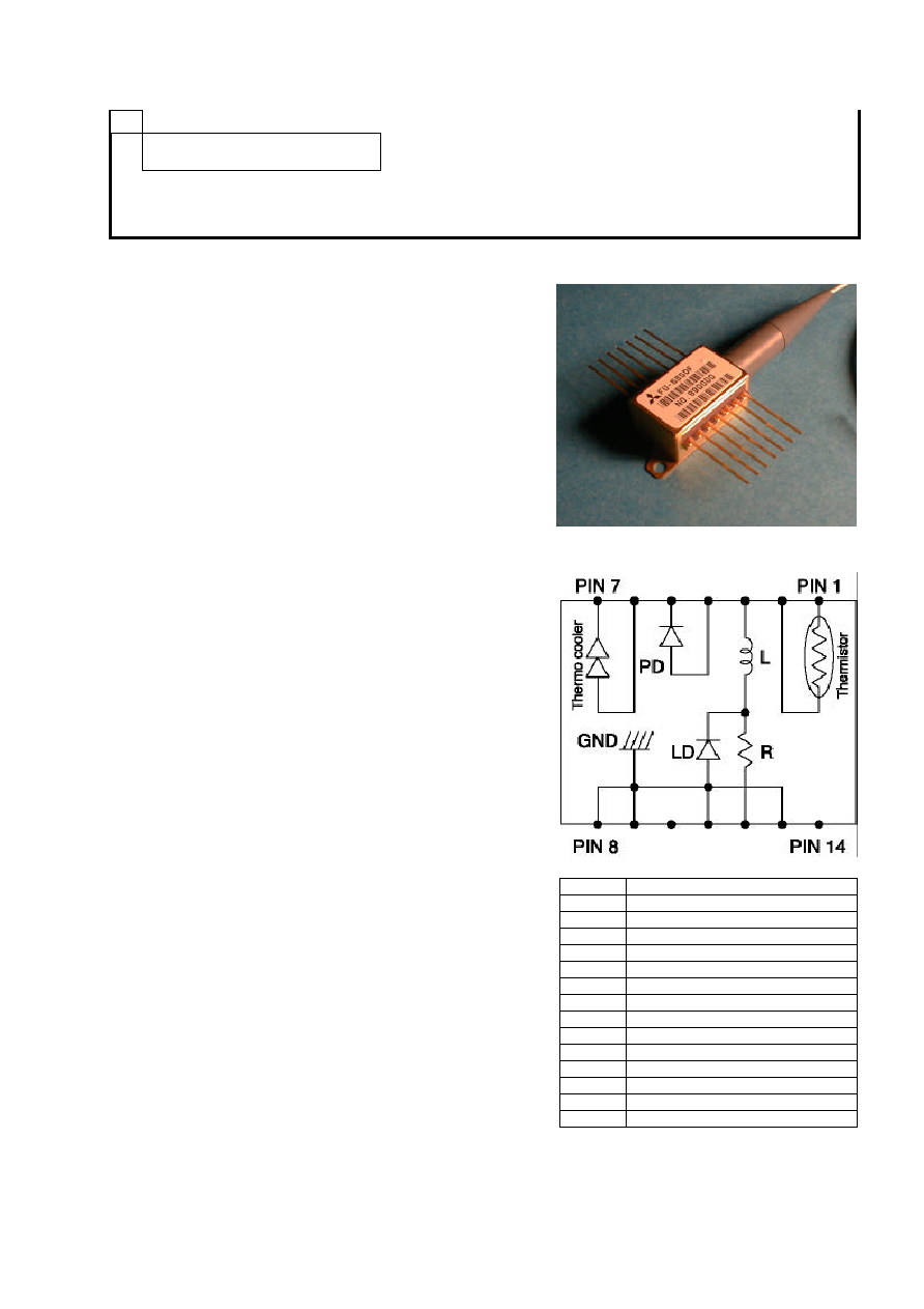
PIN INFORMATION
PIN
FUNCTION
1
Thermistor
2
Thermistor
3
LD DC Bias (Cathode)
4
PD Anode
5
PD Cathode
6
Cooler Anode
7
Cooler Cathode
8
GND
9
GND
10
NC
11
LD Anode, GND
12
LD RF Input (Cathode)
13
LD Anode, GND
14
NC
PRELIMINARY
TZ7-01-403B (3/6)
MITSUBISHI (OPTICAL DEVICES)
FU-68SDF-x910MxxB
1.55
µ
m DFB-LD MODULE WITH SINGLEMODE FIBER PIGTAIL
(WAVELENGTH SELECTED, BIAS CIRCUIT INTEGRATED, DIGITAL APPLICATION)
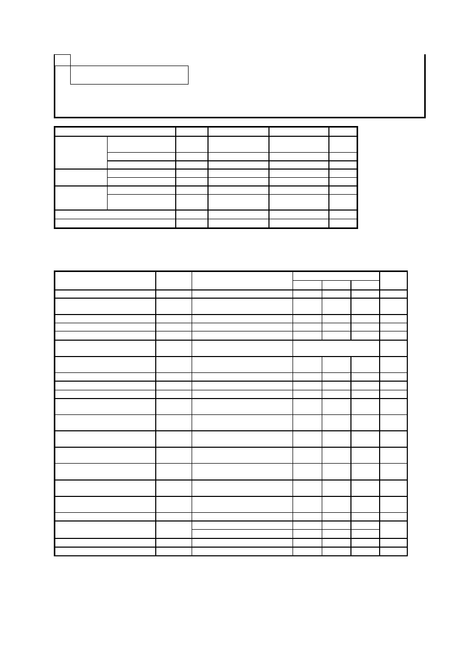
ABSOLUTE MAXIMUM RATINGS (Tld=Tset)
Parameter
Symbol
Conditions
Rating
Unit
Optical output
power
Pf
CW
15
mW
Forward current
If
CW
150
mA
Laser diode
Reverse voltage
Vrl
-
2
V
Reverse voltage
Vrd
-
20
V
Photodiode
Forward current
Ifd
-
2
mA
Cooler current
Ipe
-
1.3
A
Thermo-
electric cooler
(Note)
Cooler voltage
Vpe
-
3.1
V
Operating case temperature
Tc
-
-20 ~ 70
∞
C
Storage temperature
Tstg
-
-40 ~ 85
∞
C
Note) Even if the thermo-electric cooler (TEC) is operated within the rated conditions, uncontrolled current loading or
operation without heatsink may easily damage the module by exceeding the storage temperature range.
Thermistor resistance should be properly monitored by the feedback circuit during TEC operation to avoid the
catastrophic damage.
ELECTRICAL/OPTICAL CHARACTERISTICS (Tld=Tset, Tc=25
∞
C unless otherwise noted)
Parameter
Symbol
Test Conditions
Limits
Unit
Min.
Typ.
Max.
Threshold current
Ith
CW
-
10
25
mA
Optical output power
at threshold current
Pth
CW, If=Ith
-
-
150
µ
W
Operating current
Iop
CW, Pf=10mW
-
50
95
mA
Operating voltage
Vop
CW, Pf=10mW
-
1.3
1.8
V
Input impedance
Zin
Pf=10mW
-
25
-
Light-emission central
wavelength
c
(Note 1)
See Ordering Information
and Table 1
nm
Central wavelength drift with
case temp.
c/
Tc
Tc=-20~70
∞
C
-1
-
0
pm/
∞
C
Laser operating temperature
Tset
-
20
-
35
∞C
Spectral width
(Note 1), -20dB
-
0.2
0.4
nm
Side mode suppression ratio
Sr
(Note 1)
33
40
-
dB
Dispersion penalty
Pp
(Note 1), at 10
-10
BER,
+3000ps/nm
-
-
2
dB
Cutoff frequency
(-1.5dB optical)
fc
Pf=10mW
3.5
-
-
GHz
Rise and fall time
(10~90%)
tr, tf
(Note 1)
-
-
150
psec
Relative intensity noise
Nr
CW, Pf=10mW,
0.5~3GHz
-
-155
-145
dB/Hz
Tracking error
(Note 2)
Er
Tc=-20~70
∞
C,
APC, ATC
-
-
0.5
dB
Differential efficiency
CW, Pf=10mW
0.15
0.25
0.35
mW/
mA
Linearity
CW, Pf=1~12mW,
(Note 3)
-20
-
20
%
Monitor current
Imon
CW, Pf=10mW, Vrd=5V
0.2
-
3
mA
Tc=25∞C
35
-
-
Optical isolation
Iso
Tc=-20~70
∞
C
23
-
-
dB
Dark current (PD)
Id
Vrd=5V, Tc=-20~70
∞
C
-
-
0.1
µ
A
Capacitance (PD)
Ct
Vrd=5V, f=1MHz
-
-
10
pF
Note 1) 2.48832Gb/s NRZ, 2
23
-1, Pf_ave=5mW, Extinction ratio 9dB, optical return loss of the connectors should be
greater than 40dB in order to ensure the specified performance.
Note 2) Er=max|10
◊
log(Pf / Pf@25∞C)|
Note 3) Variation of the differential efficiency from the straight line between 1mW and 12mW.
PRELIMINARY
TZ7-01-403B (4/6)
MITSUBISHI (OPTICAL DEVICES)
FU-68SDF-x910MxxB
1.55
µ
m DFB-LD MODULE WITH SINGLEMODE FIBER PIGTAIL
(WAVELENGTH SELECTED, BIAS CIRCUIT INTEGRATED, DIGITAL APPLICATION)
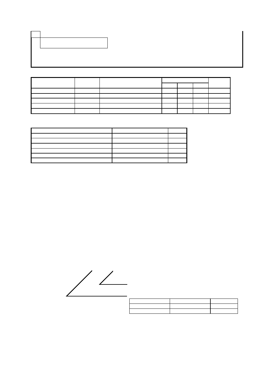
THERMAL CHARACTERISTICS (Tld=Tset, Tc=-20~70∞C)
Parameter
Symbol
Test Conditions
Limits
Unit
Min.
Typ.
Max.
Thermistor resistance
Rth
Tld=25∞C
9.5
10
10.5
k
B constant of Rth
B
-
-
3950
-
K
Cooling capacity
T
Pf=10mW, Tc=70
∞
C
50
-
-
∞
C
Cooler current
Ipe
Pf=10mW, Tc=70
∞
C, Tld=Tset
-
0.6
1
A
Cooler voltage
Vpe
Pf=10mW, Tc=70
∞
C, Tld=Tset
-
1.2
2
V
FIBER PIGTAIL SPECIFICATIONS
Parameter
Limits
Unit
Type
SM
-
Mode field diameter
9.5+/-1
µ
m
Cladding diameter
125+/-2
µ
m
Secondary coating outer diameter
0.9+/-0.1
mm
Connector
(Note 4)
-
Optical return loss of connector
40 (min)
dB
Note 4) SC/PC and FC/PC are available. Other connectors are also available for large quantities.
DOCUMENTATION (Tld=Tset)
∑
Fiber output power vs. Laser forward current at Tld=Tset and Tc=25
∞
C
∑
Threshold current (Ith)
∑
Laser forward current (Iop) at Pf=10mW
∑
Laser forward voltage (Vop) at Pf=10mW
∑
Laser operating temperature (Tset) at
c (Note 5)
∑
Monitor current (Imon) at Pf=10mW
∑
Thermistor resistance (Rth)
∑
Cooler current (Ipe) at Pf=10mW and Tc=70∞C
∑
Cooler voltage (Vpe) at Pf=10mW and Tc=70∞C
Note 5) Tset is attached as a reference data. Rth should be used in order to tune the wavelength to the specified value
accurately.
ORDERING INFORMATION
FU-68SDF-_910M__B
Code (See Table 1)
PRELIMINARY
Connector Code
Connector Code
Connector type
W
SC/PC
Standard
V
FC/PC
Optional
TZ7-01-403B (5/6)
MITSUBISHI (OPTICAL DEVICES)
FU-68SDF-x910MxxB
1.55
µ
m DFB-LD MODULE WITH SINGLEMODE FIBER PIGTAIL
(WAVELENGTH SELECTED, BIAS CIRCUIT INTEGRATED, DIGITAL APPLICATION)
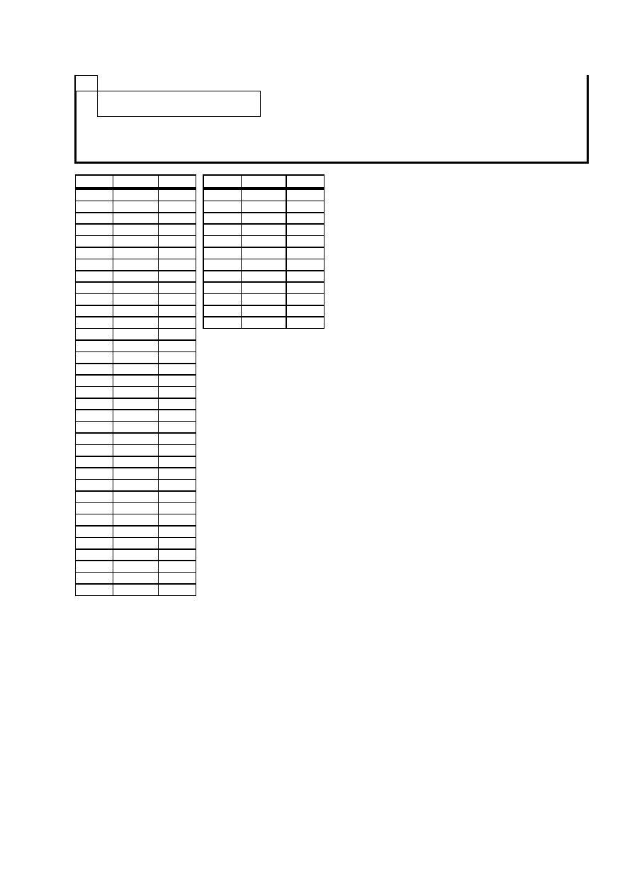
Table 1.
f [THz]
c [nm]
code
f [THz]
c [nm]
code
196.30 1527.22
3
192.80 1554.94
73
196.20 1527.99
5
192.70 1555.75
75
196.10 1528.77
7
192.60 1556.55
77
196.00 1529.55
9
192.50 1557.36
79
195.90 1530.33
11
192.40 1558.17
81
195.80 1531.12
13
192.30 1558.98
83
195.70 1531.90
15
192.20 1559.79
85
195.60 1532.68
17
192.10 1560.61
87
195.50 1533.47
19
192.00 1561.42
89
195.40 1534.25
21
191.90 1562.23
91
195.30 1535.04
23
191.80 1563.05
93
195.20 1535.82
25
191.70 1563.86
95
195.10 1536.61
27
195.00 1537.40
29
194.90 1538.19
31
194.80 1538.98
33
194.70 1539.77
35
194.60 1540.56
37
194.50 1541.35
39
194.40 1542.14
41
194.30 1542.94
43
194.20 1543.73
45
194.10 1544.53
47
194.00 1545.32
49
193.90 1546.12
51
193.80 1546.92
53
193.70 1547.72
55
193.60 1548.51
57
193.50 1549.32
59
193.40 1550.12
61
193.30 1550.92
63
193.20 1551.72
65
193.10 1552.52
67
193.00 1553.33
69
192.90 1554.13
71
All wavelengths are referred to vacuum. Tolerance is
c+/-0.05nm.
PRELIMINARY
TZ7-01-403B (6/6)
MITSUBISHI (OPTICAL DEVICES)
FU-68SDF-x910MxxB
1.55
µ
m DFB-LD MODULE WITH SINGLEMODE FIBER PIGTAIL
(WAVELENGTH SELECTED, BIAS CIRCUIT INTEGRATED, DIGITAL APPLICATION)
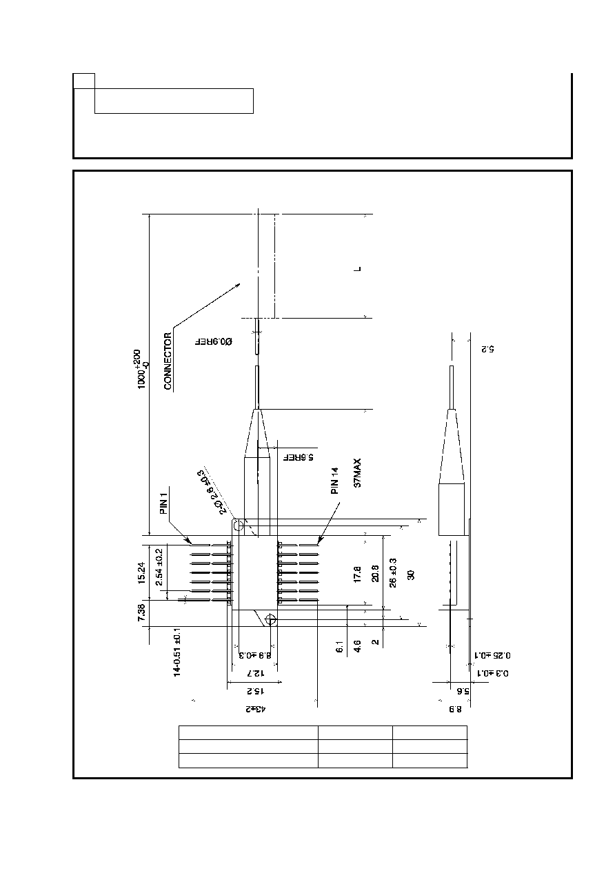
OUTLINE DIAGRAM
Unit : mm
Tolerances unless noted
±
0.5
Connector type
SC/PC
FC/PC
L
35REF
28REF
Identified type number
FU-68SDF-W910MxxB
FU-68SDF-V910MxxB
PRELIMINARY