Äîêóìåíòàöèÿ è îïèñàíèÿ www.docs.chipfind.ru

Preliminary Specification
Specifications in this manual are tentative and subject to change
Features
1-3
Mitsubishi microcomputers
M30245 Group
SINGLE-CHIP 16-BIT CMOS MICROCOMPUTER
1.0 Description
The M30245 group is a 16-bit microcomputer based on the M16C family core technology that uses the
high performance silicon gate CMOS process with an M16C/62 Series CPU core, and is packaged in a
100-pin, molded plastic QFP. They are single-chip USB peripheral microcontrollers meeting the
Universal Serial Bus (USB) Version 1.1 specification. These microcontrollers operate using
sophisticated instructions featuring a high level of instruction efficiency, making them capable of
executing instructions at high speed.
1.1 Features
· Number of instructions ........................ 91
· Shortest instruction execution time ..... 83ns f(X
IN
)=12MHz, Vcc=3V with no wait
· USB Features:..................................... 5 endpoint pairs (IN/OUT)
3.25K FIFO
Integrated transceiver
Conforms to USB V1.1 Specification
· Frequency Synthesizer........................ PLL for 48MHz clock
· Memory capacity................................. 64K ROM / 5K RAM
128K ROM / 10K RAM
128K Flash /10K RAM
· Supply Voltage .................................... 3.0 to 3.6V (f(X
IN
)=12MHz)
· Interrupts............................................. 21 internal and 5 external interrupt sources
4 software interrupt sources
7 levels (including key input interrupt X 8)
· Multifunction 16-bit timer ..................... 5 output timers+ 3 input timers
· UART................................................... 3 X 7/8/9, 2 X 7/8/9/16/24/32 bits;
Configurable for synchronous or asynchronous mode, I
2
S, I
2
C
· DMAC.................................................. 4 channels
· A-D Converter ..................................... 10 bits X 8 channels
· CRC calculation circuit ........................ 2 circuits with MSB/LSB selectable
· Watchdog timer ................................... 1 line
· Key-on Wake up .................................. 8 inputs
· Programmable I/O ............................... 84 lines (TBD)
· Clock-generating circuit....................... 2 built-in clock generation circuit
(built-in feedback resistor, and external ceramic or quartz oscillator)
1.2 Applications
USB peripherals, such as telephones, audio systems, office equipment, communications equipment,
portable equipment, scanners, and digital cameras.
1-4
Preliminary Specification
Specifications in this manual are tentative and subject to change
Pin Configuration
Mitsubishi microcomputers
M30245 Group
SINGLE-CHIP 16-BIT CMOS MICROCOMPUTER
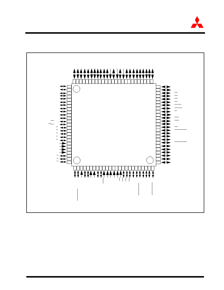
1.3 Pin Configuration
Figure 1.1 shows the pin configuration (top view).
Figure 1.1:
Pin Configuration (top view)
91
85
86
87
88
89
90
92
93
94
95
96
97
98
99
81
82
83
84
100
40
P46/CS2
P05/D5
46
P03/D3
P12/D10/LED2
P02/D2
P01/D1
P00/D0
P103/SOF/TB1in
P101/Vb
usDTCT
Ext Cap
USB D+
USB D-
LPF
AVss
P47/CS3
45
P50/WRL/WR
44
P51/WRH/BHE
43
P52/RD
42
P53/BCLK
41
P54/HLDA
P55/HOLD
39
38
37
P60/CTS0/RTS0/SS0
36
P61/CLK0/SCK0
35
P62/RxD0/SCL0/STxD0/WS0
34
P63/TxD0/SDA0/SRxD0/SD0
33
P64/CTS1/RTS1/SS1
32
P66/RxD1/SCL1/STxD1/WS1
M30245Mx/FC
P42/A18
50
P43/A19
49
P44/CS0
48
P45/CS1
47
P11/D9/LED1
P10/D8/LED0
P07/D7
P06/D6
P56/ALE
P57/RDY/CLKOUT
P04/D4
57
58
59
60
61
62
63
64
65
66
67
68
69
70
71
72
73
74
75
52
53
54
55
56
51
31
Vref
AVcc
P97/AN7/KI7
P96/AN6/KI6
P95/AN5/KI5
P67/TxD1SDA1/SRxD1/SD1
P70/TxD2/SDA2/SRxD2/TA0out
P71/RxD2/SCL2/STxD2/TA0in
P72/CLK2/TA1out
P93/AN3/KI3
P92/AN2/KI2
P91/AN1/KI1
P90/AN0/KI0
BYTE
CNVss
P87/XCin
P86/XCout
RESET
Xout
Vss
Xin
Vcc
P85/
NMI
P84/
INT2
P83/
INT1
P82/CLK4/
INT0
P81/RxD4/SCL4/STxD4//T
A4in
P80/TxD4/SD
A4/SRxD4//T
A4out
P77/
CTS3/
R
TS3/
SS3//T
A3in
P76/CLK3/T
A3out
P75/RxD3/SCL3/STxD3/T
A2in
P74/TxD3/SD
A3/SRxD3/T
A2out
P73/
CTS2/
R
TS2/
SS2/T
A1in
2
1
24
23
22
21
20
19
18
17
16
15
14
13
12
11
10
9
8
7
6
5
4
3
25
30
29
28
27
26
P40/A16
P37/A15
P36/A14
P35/A13
P32/A10
P34/A12
Vcc
P31/A9
P30/A8
Vss
P27/A7
P26/A6
P25/A5
P24/A4
P23/A3
P22/;A2
P21/A1
P20/A0
P17/D15LED7
P16/D14LED6
P15/D13/LED5
P14/D12/LED4
P13/D11/LED3
P41/A17
P33/A11
80
79
78
77
76
100-pin QFP (0.5mm pitch)
P65/CLK1/SCK1
P102/AD
TRIG
/TB0in
P94/AN4/KI4
P100/
CTS4/
R
TS4/
SS4/TB2in/A
TT
A
C
H
Preliminary Specification
Specifications in this manual are tentative and subject to change
Block Diagram
1-5
Mitsubishi microcomputers
M30245 Group
SINGLE-CHIP 16-BIT CMOS MICROCOMPUTER
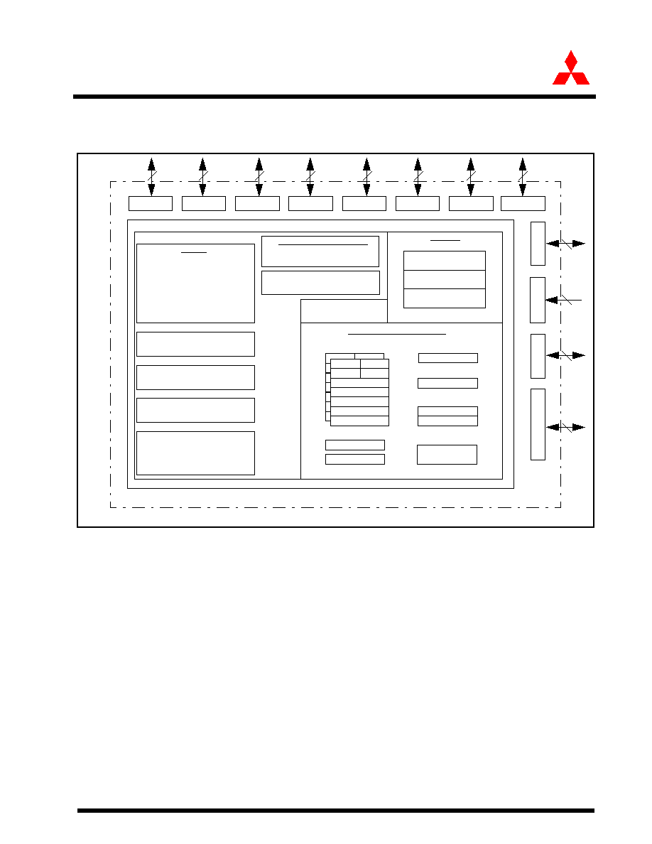
1.4 Block Diagram
Figure 1.2 is a block diagram of the M30245 group.
Figure 1.2:
Block diagram of M30245 group
A1
FB
Port P0
Port P1
Port P2
Port P3
Port P4
Port P5
Port P6
P
o
r
t
P8
P
o
r
t
P9
P
o
r
t
P10
0
-10
3
INTB
PC
FLG
R0H
R0L
R1H
R1L
R2
R3
A0
A1
FB
R0H
R0L
R1H
R1L
R2
R3
SB
Multiplier
M16C/62 16-bit CPU Core
ROM/FLASH
RAM
Memory
CRC Arithmetic Circuit
(X
16
+X
12
+X
5
+1, X
16
+X
15
+X
2
+1)
UART/Clock Synchronous SI/O
(8 bits X 5 channels)
A-D Converter
(10 bits X 8 channels)
DMAC
(4 channels)
USB Function
(10K bytes)
USB FIFO
(3.25K bytes)
Timers
Timer TA0 (16 bits)
Timer TA1 (16 bits)
Timer TA2 (16 bits)
Timer TA3 (16 bits)
Timer TA4 (16 bits)
Timer TB0 (16 bits)
Timer TB1 (16 bits)
Timer TB2 (16 bits)
System Clock Generator
Xin - Xout
Xcin - Xcout
Watchdog Timer
(15 bits)
with frequency synthesizer
Internal Peripheral Functions
8
8
8
8
8
8
8
7
4
(128K bytes)
Port P7
8
8
A0
USP
ISP
Program counter
Vector table
Stack pointer
Registers
P
o
r
t
P8
5
1
1-6
Preliminary Specification
Specifications in this manual are tentative and subject to change
Performance outline
Mitsubishi microcomputers
M30245 Group
SINGLE-CHIP 16-BIT CMOS MICROCOMPUTER
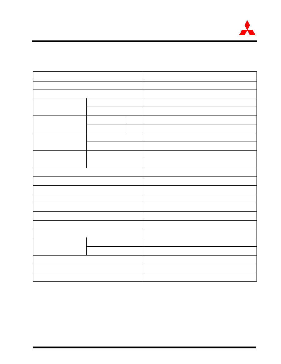
1.5 Performance outline
Table 1.1 is a performance outline of the M30245 group.
Table 1.1:
Performance outline of M16C/M30245 Group
Parameters
Function Description
Number of basic Instructions
91
Shortest Instruction execution time
83 ns f(Xin)= 12 MHz, Vcc = 3V
Memory size
ROM
128/64 Kbytes
RAM
10/5 Kbytes
Input/Output ports
P0~P9
I/O
8 bits x 10
P100~P101
I/O
2 bits x 1
Multifunction timer
TA0, TA1, TA2, TA3, TA4
16 bits x 5
TB0, TB1, TB2
16 bits x 3
Serial I/O
UART0~1
UART (or clock synchronous or IIS) x 2
UART2~4
UART (or clock synchronous) x 3
A-D converter
10 bits x 8 channels
DMAC
4 channels
CRC calculation circuits
CRC-CCITT and CRC-16
Watchdog timer
15 bits x 1 (prescaler)
Interrupts
21 internal, 4 external sources, 4 software, 7 levels
Clock-generating circuit
2 built-in clock generating circuit
Supply voltage
3.0 ~ 3.6V, f(X
IN
) = 12MHz
Power consumption
TBD
I/O characteristics
I/O withstand voltage
3V
Output current
5mA (20mA available on P1, P70, P72, P74, P76, P80)
Operating temperature
-20 to 85 C
Device configuration
CMOS high performance silicon gate
Package
100-pin plastic mold QFP
Preliminary Specification
Specifications in this manual are tentative and subject to change
Performance outline
1-7
Mitsubishi microcomputers
M30245 Group
SINGLE-CHIP 16-BIT CMOS MICROCOMPUTER
Mitsubishi plans to release the following products in the M30245 group:
(1) Support for Flash memory version and mask ROM versions
(2) ROM capacity: 128 or 64 Kbytes
(3) Package
·
100P6Q-A: Plastic molded QFP
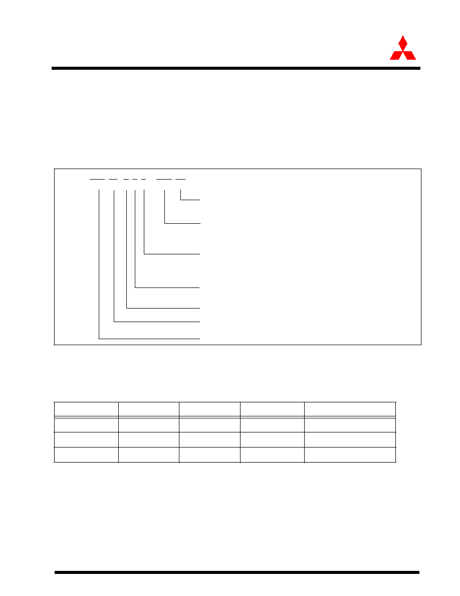
Figure 1.3 shows the type number, memory size and package for the M30245 group.
Figure 1.3:
Type number, memory size, and package
Table 1.2 shows the package number, type, ROM and RAM capacity for M30245 Group.
Table 1.2:
M30245 Group
Type No. M30 24 X F 8 - XXX FP
Package type:
GP:
Package
100P6Q-A
ROM No.:
Omitted for flash memory version
ROM capacity:
4: 32Kbytes
8: 64Kbytes
A: 96Kbytes
C: 128Kbytes
G: 256Kbytes
Memory type:
M: Mask ROM version
F: Flash memory version
Shows pin count, etc:
The value itself has no specific meaning
M16C/M30245 Group
M16C Family
Type
ROM Capacity
RAM Capacity
Package Type
Remarks
M30245FCGP
128K bytes
10K bytes
100P6Q-A
Flash ROM Version
M30245MCGP
128K bytes
10K bytes
100P6Q-A
Mask ROM Version
M30245M8GP
64K bytes
5K bytes
100P6Q-A
Mask ROM Version