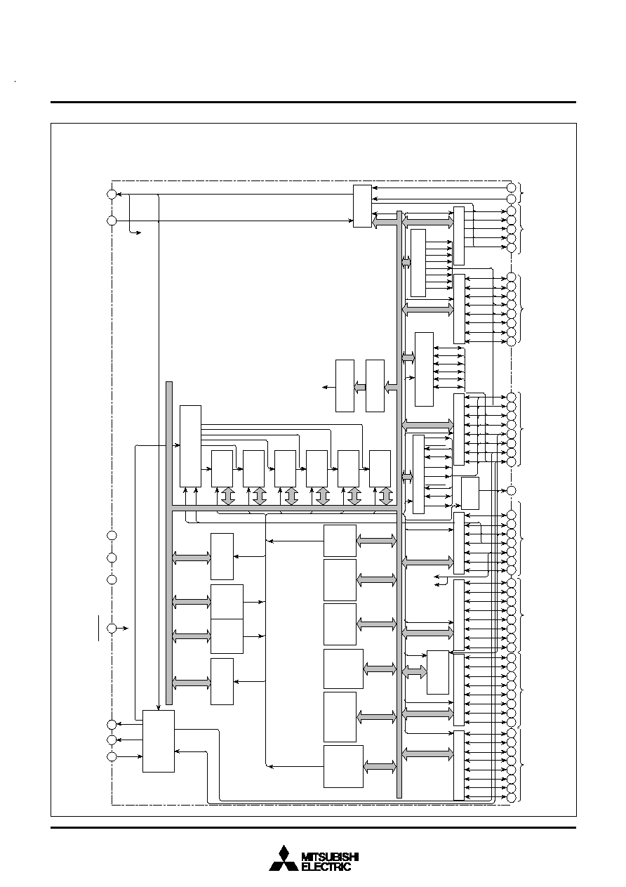
DESCRIPTION
The M37207MF-XXXSP/FP and M37207M8-XXXSP are single-chip
microcomputers designed with CMOS silicon gate technology. It is
housed in a 64-pin shrink plastic molded DIP or a 80-pin plastic molded
QFP.
In addition to their simple instruction sets, the ROM, RAM and I/O
addresses are placed on the same memory map to enable easy pro-
gramming.
The M37207MF-XXXSP/FP has a PWM function and an OSD func-
tion, so it is useful for a channel selection system for TV. The fea-
tures of the M37207EFSP/FP are similar to those of the M37207MF-
XXXSP/FP except that these chips have a built-in PROM which can
be written electrically. The difference between M37207MF-XXXSP/
FP and M37207M8-XXXSP are the ROM size, RAM size, ROM size
for display and kinds of character. Accordingly, the following descrip-
tions will be for the M37207MF-XXXSP/FP unless otherwise noted.
∑
Multi-master I
2
C-BUS interface ............................... 1 (3 systems)
∑
Power dissipation
In high-speed mode ........................................................ 165 mW
(at V
CC
= 5.5 V, 8 MHz oscillation frequency, CRT on)
In low-speed mode ......................................................... 0.33 mW
(at V
CC
= 5.5 V, 32 kHz oscillation frequency)
∑
A-D comparator (6-bit resolution) ................................ 8 channels
∑
PWM output circuit ...................................... 14-bit
!
1, 8-bit
!
10
∑
Interrupt interval determination circuit ........................................ 1
∑
ROM correction function .......................................... 32 bytes
!
2
∑
CRT display function
Number of display characters ............... 24 characters
!
3 lines
(16 lines maximum)
Kinds of characters .................. 256 kinds (M37207M8-XXXSP)
384 kinds (M37207MF-XXXSP/FP,
M37207EFSP/FP)
Character display area .......................................... 12
!
16 dots
Kinds of character sizes ................................................. 4 kinds
Kinds of character colors (It can be specified by the character)
maximum 15 kinds (R, G, B, I)
Kinds of character background colors (It can be specified by the character)
maximum 7 kinds (R, G, B)
1/2-character unit color specification is possible.
Kinds of raster colors (maximum 15 kinds)
Display position
Horizontal .................................................................. 64 levels
Vertical .................................................................... 128 levels
Bordering (horizontal and vertical)
Wipe function
Scanning line double count mode display is possible.
APPLICATION
TV
FEATURES
∑
Number of basic instructions .................................................... 71
∑
Memory size .................................................................................
ROM ...................... 32K bytes (M37207M8-XXXSP)
62K bytes (M37207MF-XXXSP/FP,
M37207EFSP/FP)
RAM ...................... 512 bytes (M37207M8-XXXSP)
960 bytes (M37207MF-XXXSP/FP,
M37207EFSP/FP)
ROM correction memory ............................ 64 bytes
ROM for display ....... 8K bytes (M37207M8-XXXSP)
12K bytes (M37207MF-XXXSP/FP,
M37207EFSP/FP)
RAM for display ........................................ 144 bytes
∑
Minimum instruction execution time
........................................ 0.5
µs (at 8 MHz oscillation frequency)
∑
Power source voltage .................................................. 5 V ± 10 %
∑
Subroutine nesting ............................................ 128 levels (Max.)
∑
Interrupts ...................................................... 15 types, 14 vectors
∑
8-bit timers ................................................................................. 6
∑
Programmable I/O ports
(Ports P0, P1, P2, P3
0
≠P3
6
, P4, P6) ....................................... 47
∑
Input ports (Ports P7
0
, P7
1
) ....................................................... 2
∑
Output ports (Ports P5
2
≠P5
6
) ..................................................... 5
∑
12 V withstand ports ................................................................. 10
∑
LED drive ports .......................................................................... 4
∑
Serial I/O ....................................... 8-bit
!
1 channel (2 systems)
MITSUBISHI MICROCOMPUTERS
M37207MF-XXXSP/FP, M37207M8-XXXSP
M37207EFSP/FP
SINGLE-CHIP 8-BIT CMOS MICROCOMPUTER for VOLTAGE SYNTHESIZER
and ON-SCREEN DISPLAY CONTROLLER

MITSUBISHI MICROCOMPUTERS
M37207MF-XXXSP/FP, M37207M8-XXXSP
M37207EFSP/FP
SINGLE-CHIP 8-BIT CMOS MICROCOMPUTER for VOLTAGE SYNTHESIZER
and ON-SCREEN DISPLAY CONTROLLER
5
Number of basic instructions
Instruction execution time
Clock frequency
Memory size
Input/Output ports
Serial I/O
Multi-master I
2
C-BUS interface
A-D comparator
PWM output circuit
Timers
ROM correction function
Subroutine nesting
Interrupt interval determination circuit
Interrupt
Clock generating circuit
P0
0
≠P0
7
P1
0
≠P1
7
P2
0
≠P2
7
P3
0
, P3
1
P3
2
≠P3
6
P4
0
≠P4
7
P5
2
≠P5
6
P6
0
≠P6
7
P7
0
, P7
0
ROM
RAM
CRT ROM
CRT RAM
Parameter
71
0.5
m
s (the minimum instruction execution time, at 8 MHz oscillation fre-
quency)
8 MHz (maximum)
32 K bytes
64 K bytes
512 bytes
960 bytes
64 bytes
8K bytes
12K bytes
144 bytes
8-bit
!
1 (CMOS input/output structure)
8-bit
!
1 (CMOS input/output structure)
8-bit
!
1 (CMOS input/output structure)
2-bit
!
1 (CMOS input/output structure)
5-bit
!
1 (N-channel open-drain output structure, can be used as external
clock input pins, A-D input pins, INT input pins)
8-bit
!
1 (N-channel open-drain output structure, can be used as serial I/O
pins, A-D input pins, PWM output pins, multi-master I
2
C-BUS interface,
sub-clock I/O pins)
5-bit
!
1 (CMOS output structure, can be used as CRT output pins, an
external clock output pin)
8-bit
!
1 (N-channel open-drain output structure, can be used as PWM
output)
2-bit
!
1 (can be used as CRT display clock I/O pins, analog input pins)
8-bit
!
1 (2 systems)
1 (3 systems)
8 channels (6-bit resolution)
14-bit
!
1, 8-bit
!
10
8-bit timer
!
6
32 bytes
!
2
128 levels (maximum)
1
External interrupt
!
2, Internal timer interrupt
!
6, Serial I/O interrupt
!
1,
CRT interrupt
!
1, Multi-master I
2
C-BUS interface interrupt
!
1,
f(X
IN
)/4096 interrupt
!
1, V
SYNC
interrupt
!
1, BRK interrupt
!
1
2 built-in circuits (externally connected to a ceramic resonator or a quartz-
crystal oscillator)
I/O
I/O
I/O
I/O
I/O
I/O
Output
I/O
Input
Functions
FUNCTIONS
ROM correction memory
M37207M8-XXXSP
M37207MF-XXXSP/FP,
M37207EFSP/FP
M37207M8-XXXSP
M37207MF-XXXSP/FP,
M37207EFSP/FP
M37207M8-XXXSP
M37207MF-XXXSP/FP,
M37207EFSP/FP