DESCRIPTION
The M37271MF-XXXSP is a single-chip microcomputer designed with
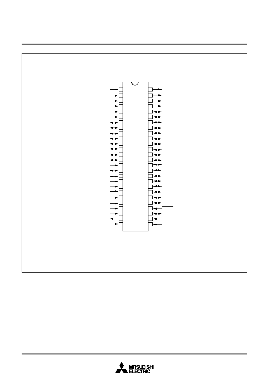
CMOS silicon gate technology. It is housed in a 52-pin shrink plastic
molded DIP.
In addition to their simple instruction sets, the ROM, RAM and I/O
addresses are placed on the same memory map to enable easy pro-
gramming.
The M37271MF-XXXSP has a OSD function and a data slicer func-
tion, so it is useful for a channel selection system for TV with a closed
caption decoder. The features of the M37271EF-XXXSP and the
M37271EFSP are similar to those of the M37271MF-XXXSP except
that these chips have a built-in PROM which can be written electri-
cally.
FEATURES
�
Number of basic instructions ..................................................... 71
�
Memory size
ROM ........................................................ 60 K bytes
RAM ........................................................ 1024 bytes
ROM for OSD ....................................... 14464 bytes
RAM for OSD ......................................... 1920 bytes
�
The minimum instruction execution time
.......................................... 0.5
�s (at 8 MHz oscillation frequency)
�
Power source voltage .................................................. 5 V � 10 %
�
Subroutine nesting ............................................. 128 levels (Max.)
�
Interrupts ....................................................... 18 types, 16 vectors
�
8-bit timers .................................................................................. 6
�
Programmable I/O ports (Ports P0, P1, P2, P3
0
, P3
1
) .............. 26
�
Input ports (Ports P4
0
�P4
6
, P6
3
, P6
4
) ......................................... 9
�
Output ports (Ports P5
2
�P5
5
) ...................................................... 4
�
12 V withstand ports .................................................................. 11
�
LED drive ports ........................................................................... 2
�
Serial I/O ............................................................ 8-bit
!
1 channel
�
Multi-master I
2
C-BUS interface ............................... 1 (2 systems)
�
A-D converter (8-bit resolution) ................................... 4 channels
�
PWM output circuit ........................................................... 8-bit
!
7
�
Interrupt interval determination circuit ......................................... 1
�
Power dissipation
In high-speed mode .......................................................... 165mW
(at V
CC
= 5.5V, 8MHz oscillation frequency, CRT on, and Data
slicer on)
In low-speed mode .......................................................... 0.33mW
(at V
CC
= 5.5V, 32kHz oscillation frequency)
�
Data slicer
�
OSD function
Display characters ............................... 40 characters
!
16 lines
Kinds of characters ..................................................... 320 kinds
(In EXOSD mode, they can be combined with 32 kinds of extra
fonts)
Dot structure ........................................ CC mode : 16
!
26 dots
OSD mode : 16
!
20 dots
EXOSD mode : 16
!
26 dots
Kinds of character sizes ................................ CC mode : 2 types
OSD mode : 14 types
EXOSD mode : 6 types
It can be specified by a character unit (maximum 7 kinds).
Character font coloring, character background coloring
It can be specified by a screen unit (maximum 7 kinds).
Extra font coloring, raster coloring, border coloring
Kinds of character colors ............... CC mode : 7 kinds (R, G, B)
OSD mode : 15 kinds (R, G, B, I)
EXOSD mode : 7 kinds (R, G, B, I1, I2)
Display position
Horizontal ................................................................ 256 levels
Vertical .................................................................. 1024 levels
Attribute ...................... CC mode : smooth italic, underline, flash
OSD mode : border
EXOSD mode : border,
extra font (32 kinds)
Automatic solid space function
Window function
Dual layer OSD function
APPLICATION
TV with a closed caption decoder
MITSUBISHI MICROCOMPUTERS
M37271MF-XXXSP
M37271EF-XXXSP, M37271EFSP
SINGLE-CHIP 8-BIT CMOS MICROCOMPUTER with CLOSED CAPTION DECODER
and ON-SCREEN DISPLAY CONTROLLER

MITSUBISHI MICROCOMPUTERS
M37271MF-XXXSP
M37271EF-XXXSP, M37271EFSP
SINGLE-CHIP 8-BIT CMOS MICROCOMPUTER with CLOSED CAPTION DECODER
and ON-SCREEN DISPLAY CONTROLLER
4
71
0.5
�
s (the minimum instruction execution time, at 8 MHz oscillation fre-
quency)
8 MHz (maximum)
60 K bytes
1024 bytes
14464 bytes
1920 bytes
7-bit
!
1 (N-channel open-drain output structure, can be used as PWM
output pins)
1-bit
!
1 (CMOS input/output structure)
4-bit
!
1 (CMOS input/output structure, can be used as OSD output pin,
INT input pin, serial input pin)
4-bit
!
1 (N-channel open-drain output structure, can be used as multi-
master I
2
C-BUS interface)
8-bit
!
1 (CMOS input/output structure, can be used as A-D input pins)
2-bit
!
1 (CMOS input/output structure)
5-bit
!
1 (can be used as A-D input pins, INT input pins, external clock
input pins)
2-bit
!
1 (N-channel open-drain output structure when serial I/O is used,
can be used as serial I/O pins)
4-bit
!
1 (CMOS output structure, can be used as OSD output)
1-bit
!
1 (can be used as sub-clock input pin, OSD clock input pin)
1-bit
!
1 (CMOS output structure when LC is oscillating, can be used as
sub-clock output pin, OSD clock output pin)
8-bit
!
1
1
4 channels (8-bit resolution)
8-bit
!
7
8-bit timer
!
6
128 levels (maximum)
1
External interrupt
!
3, Internal timer interrupt
!
6, Serial I/O interrupt
!
1,
OSD interrupt
!
1, Multi-master I
2
C-BUS interface interrupt
!
1,
Data slicer interrupt
!
1, f(X
IN
)/4092 interrupt
!
1, V
SYNC
interrupt
!
1, A-
D conversion interrupt
!
1, BRK instruction interrupt
!
1
2 built-in circuits (externally connected a ceramic resonator or a quartz-
crystal oscillator)
Built in
Parameter
Functions
FUNCTIONS
Number of basic instructions
Instruction execution time
Clock frequency
Memory size
Input/Output ports
Serial I/O
Multi-master I
2
C-BUS interface
A-D converter
PWM output circuit
Timers
Subroutine nesting
Interrupt interval determination circuit
Interrupt
Clock generating circuit
Data slicer
ROM
RAM
OSD ROM
OSD RAM
P0
0
�P0
2
,
P0
4
�P0
7
P0
3
P1
0
, P1
5
�P1
7
P1
1
�P1
4
P2
P3
0
, P3
1
P4
0
�P4
4
P4
5
, P4
6
P5
2
�P5
5
P6
3
P6
4
I/O
I/O
I/O
I/O
I/O
I/O
Input
Input
Output
Input
Input

MITSUBISHI MICROCOMPUTERS
M37271MF-XXXSP
M37271EF-XXXSP, M37271EFSP
SINGLE-CHIP 8-BIT CMOS MICROCOMPUTER with CLOSED CAPTION DECODER
and ON-SCREEN DISPLAY CONTROLLER
5
5 V � 10 %
165 mW typ. (at oscillation frequency f
CPU
= 8 MHz, f
OSD
= 13 MHz)
82.5 mW typ. (at oscillation frequency f
CPU
= 8 MHz)
0.33mW typ. (at oscillation frequency f
CLK
= 32 kHz, f(X
IN
) = stopped)
0.055 mW (maximum)
�10 �C to 70 �C
CMOS silicon gate process
52-pin shrink plastic molded DIP
Number of display characters
Dot structure
Kinds of characters
Kinds of character sizes
Kinds of character colors
Display position (horizontal, vertical)
FUNCTIONS (continued)
OSD function
Power source voltage
Power dissipation
40 characters
!
16 lines
CC mode: 16
!
26 dots (character part : 16
!
20 dots)
OSD mode: 16
!
20 dots
EXOSD mode: 16
!
26 dots
320 kinds
(In EXOSDmode, they can be combined with 32 kinds of extra fonts)
CC mode: 2 kinds
OSD mode: 14 kinds
EXOSD mode: 6 kinds
CC mode: 7 kinds (R, G, B)
OSD mode: 15 kinds (R, G, B, I1)
EXOSD mode: 7 kinds (R, G, B, I1, I2)
256 levels (horizontal)
!
1024 levels (vertical)
Data slicer ON
Data slicer OFF
Data slicer OFF
In high-speed
mode
In low-speed
mode
In stop mode
OSD ON
OSD OFF
OSD OFF
Operating temperature range
Device structure
Package