
keep safety first in your circuit designs !
q
Mitsubishi Electric Corporation puts the maximum effort into making semiconductor
products better and more reliable, but there is always the possibility that trouble
may occur with them. Trouble with semiconductors may lead to personal injury,
fire or property damage. Remember to give due consideration to safety when
making your circuit designs, with appropriate measures such as (i) placement
of substitutive, auxiliary circuits, (ii) use of non-flammable material or (iii) prevention
against any malfunction or mishap.
Notes regarding these materials
q
These materials are intended as a reference to assist our customers in the
selection of the Mitsubishi semiconductor product best suited to the customer's
application; they do not convey any license under any intellectual property rights,
or any other rights, belonging to Mitsubishi Electric Corporation or a third party.
q
Mitsubishi Electric Corporation assumes no responsibility for any damage, or
infringement of any third-party's rights, originating in the use of any product
data, diagrams, charts or circuit application examples contained in these materials.
q
All information contained in these materials, including product data, diagrams
and charts, represent information on products at the time of publication of these
materials, and are subject to change by Mitsubishi Electric Corporation without
notice due to product improvements or other reasons. It is therefore recommended
that customers contact Mitsubishi Electric Corporation or an authorized Mitsubishi
Semiconductor product distributor for the latest product information before
purchasing a product listed herein.
q
Mitsubishi Electric Corporation semiconductors are not designed or manufactured
for use in a device or system that is used under circumstances in which human
life is potentially at stake. Please contact Mitsubishi Electric Corporation or an
authorized Mitsubishi Semiconductor product distributor when considering the
use of a product contained herein for any specific purposes, such as apparatus
or systems for transportation, vehicular, medical, aerospace, nuclear, or undersea
repeater use.
q
The prior written approval of Mitsubishi Electric Corporation is necessary to
reprint or reproduce in whole or in part these materials.
q
If these products or technologies are subject to the Japanese export control
restrictions, they must be exported under a license from the Japanese government
and cannot be imported into a country other than the approved destination.
Any diversion or reexport contrary to the export control laws and regulations of
Japan and/or the country of destination is prohibited.
q
Please contact Mitsubishi Electric Corporation or an authorized Mitsubishi
Semiconductor product distributor for further details on these materials or the
products contained therein.

Preface
This user's manual describes Mitsubishi's CMOS 8-
bit microcomputers 3802 Group.
After reading this manual, the user should have a
through knowledge of the functions and features of
the 3802 Group, and should be able to fully utilize
the product. The manual starts with specifications
and ends with application examples.
For details of software, refer to the "SERIES MELPS
740 <SOFTWARE> USER'S MANUAL."
For details of development support tools, refer to the
"DEVELOPMENT SUPPORT TOOLS FOR MICRO-
COMPUTERS" data book.
BEFORE USING THIS USER'S MANUAL
This user's manual consists of the following three chapters. Refer to the chapter appropriate to your conditions, such
as hardware design or software development. Chapter 3 also includes necessary information for systems development.
Be sure to refer to this chapter.
1. Organization
q
CHAPTER 1 HARDWARE
This chapter describes features of the microcomputer and operation of each peripheral function.
q
CHAPTER 2 APPLICATION
This chapter describes usage and application examples of peripheral functions, based mainly on setting examples
of related registers.
q
CHAPTER 3 APPENDIX
This chapter includes necessary information for systems development using the microcomputer, electric
characteristics, a list of registers, the masking confirmation (mask ROM version), and mark specifications which
are to be submitted when ordering.
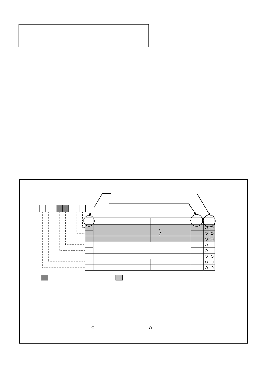
2. Structure of register
The figure of each register structure describes its functions, contents at reset, and attributes as follows :
0 0 : Single-chip mode
Note 2. Bit attributes∑∑∑∑∑∑The attributes of control register bits are classified into 3 bytes : read-only, write-only
and read and write. In the figure, these attributes are represented as follows :
: Bit in which nothing is arranged
0 1 :
Name
Function
At reset
R W
B
0
1
2
3
4
0
0
0
0
0
!
!
5
6
7
1
T
b0
b1
b2
b3
b4
b5
b6
b7
Contents immediately after reset release
Bit attributes
(Note 1)
Processor mode bits
Stack page selection bit
Nothing arranged for these bits. These are write disabled
bits. When these bits are read out, the contents are "0."
Fix this bit to "0."
Main clock (X
IN
-X
OUT
) stop bit
Internal system clock selection bit
1 0 :
1 1 :
Not available
b1 b0
0 : 0 page
1 : 1 page
0 : Operating
1 : Stopped
0 : X
IN
-X
OUT
selected
1 : X
CIN
-X
COUT
selected
: Bit that is not used for control of the corresponding function
0
Note 1. Contents immediately after reset release
0∑∑∑∑∑∑"0" at reset release
1∑∑∑∑∑∑"1" at reset release
Undefined∑∑∑∑∑∑Undefined or reset release
∑∑∑∑∑∑Contents determined by option at reset release
T
R∑∑∑∑∑∑Read
∑∑∑∑∑∑Read enabled
!
∑∑∑∑∑∑Read disabled
W∑∑∑∑∑∑Write
∑∑∑∑∑∑Write enabled
!
∑∑∑∑∑∑Write disabled
(Note 2)
T
CPU mode register (CPUM) [Address : 3B
16
]
Bits
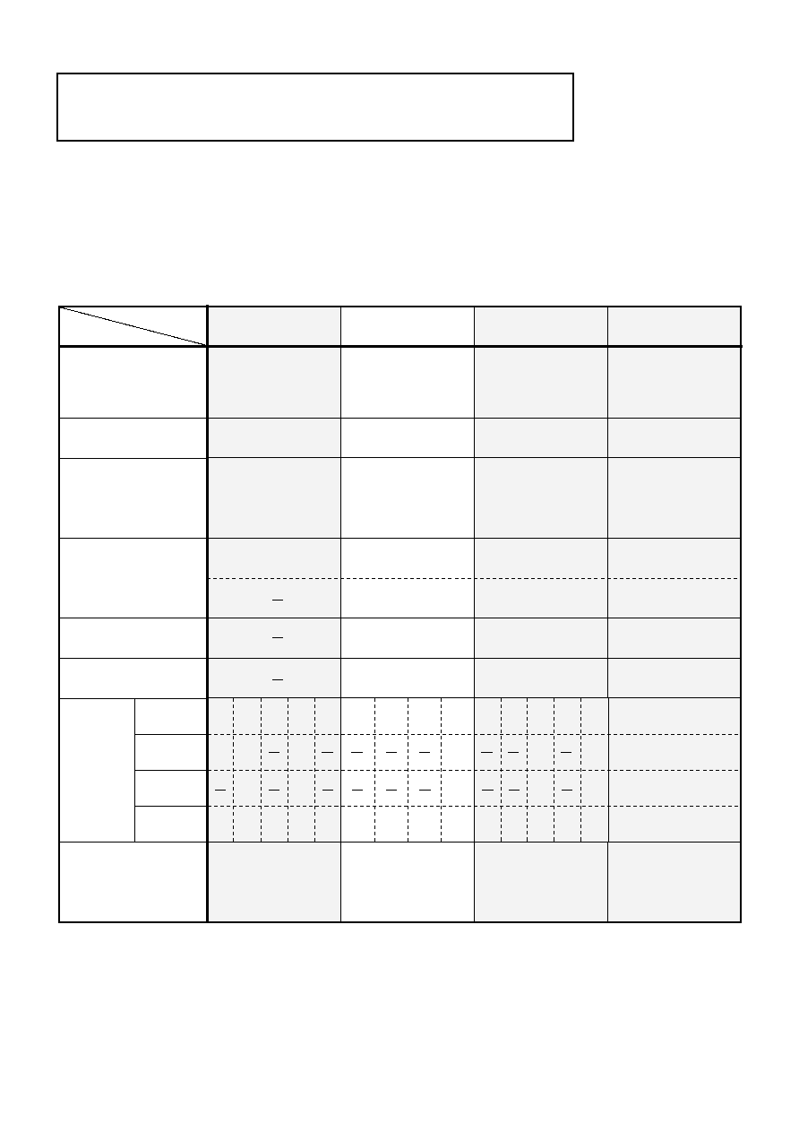
LIST OF GROUPS HAVING THE SIMILAR FUNCTIONS
Prescaler : 3
Timer : 4
<8-bit>
Prescaler : 3
Timer : 4
<8-bit>
Prescaler : 3
Timer : 4
<8-bit>
Function
Group
Pin
(Package type)
Timer
A-D converter
D-A converter
Clock generating circuit
Serial I/O
Remarks
One Time
PROM
EPROM
RAM
Mask
ROM
Memory
type
V
24K
512
384
32K
8K
16K
32K
16K
(Note 1)
8K
(Note 1)
16K
(Note 1)
32K
(Note 1)
384 384
640
8K
(Note 1)
24K
384
384
640
16K
(Note 1)
32K
(Note 1)
32K
(Note 1)
32K
1024
PWM output
512
16K
16K
16K
3800 group
64 pin
∑ 64P4B
∑ 64P6N-A
∑ 64P6D-A
1 circuit
UART or
Clock synchronous
!
1
3802 group
64 pin
∑ 64P4B
∑ 64P6N-A
8-bit
!
8-channel
8-bit
!
2-channel
UART or
Clock synchronous
!
1
Clock synchronous
!
1
1 circuit
1 circuit
UART or
Clock synchronous
!
1
Clock synchronous
!
1
3806 group
3807 group
80 pin
∑ 80P6N-A
2 circuit
8-bit
!
13-channel
8-bit
!
4-channel
UART or
Clock synchronous
!
1
Clock synchronous
!
1
Timer : 3
<8-bit>
Timer X/Y : 2
Timer A/B : 2
<16-bit>
80 pin
∑ 80P6N-A
∑ 80P6S-A
∑ 80P6D-A
12K
(Note 1)
16K
(Note 1)
24K
(Note 3)
24K
32K
(Note 3)
48K
(Note 3)
1024
512
384 384
1024
24K
(Note 2)
48K
(Note 3)
8-bit
!
8-channel
8-bit
!
2-channel
As of September 1995
Real time port output
Analog comparator
Watchdog timer
48K
(Note 2)
Notes 1: Extended operating temperature version available
2: High-speed version available
3: Extended operating temperature version and High-speed version available
V
. ROM expansion
3802 group, one of the CMOS 8-bit microcomputer 38000 series presented in this user's manual is provided with
standard functions.
The basic functions of the 3800, 3802, 3806 and 3807 groups having the same functions are shown below. For the
detailed functions of each group, refer to the related data book and user's manual.
List of groups having the same functions