MITSUMI
Video Amplifier MM1002
Video Amplifier
Monolithic IC MM1002
Outline
This IC is a video amplifier that can perform superimpose. It has a built-in 75
driver.
Features
1. Built-in superimpose function
2. Built-in Y-C mix circuit
3. Vertical/horizontal sync signal output pin
4. Built-in clamp circuit (for Y signal only)
5. 75
driver built in
6. EVF driver built in
7. External pin (Pin 14) allows fine tuning of character level
8. Frequency response
5MHz
9. Power supply voltage
4.7V~5.3V
Package
SOP-16A (MM1002F)
Applications
1. TV
2. VCR
3. VCR with camera
4. Other video equipment
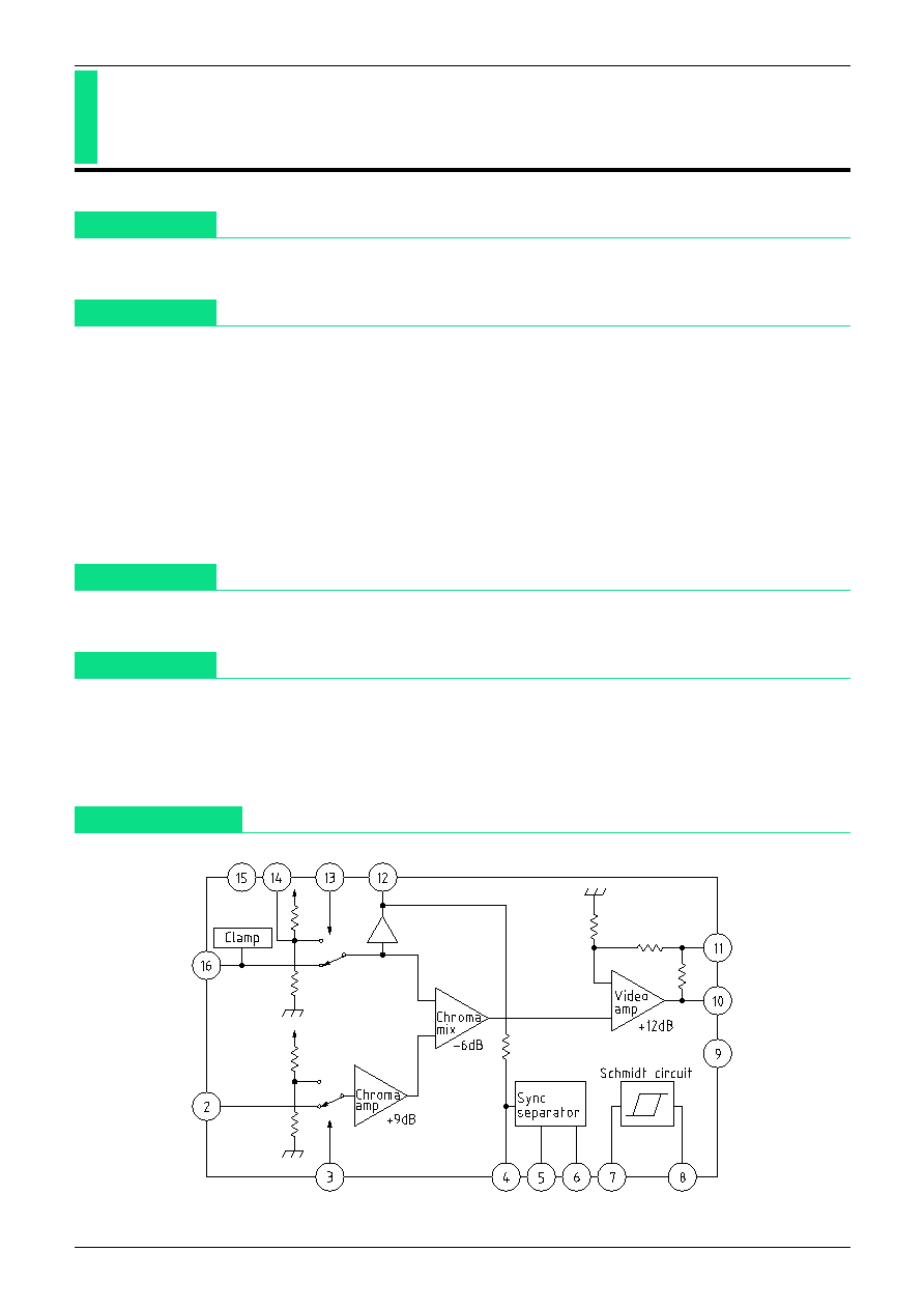
Block Diagram
MITSUMI
Video Amplifier MM1002
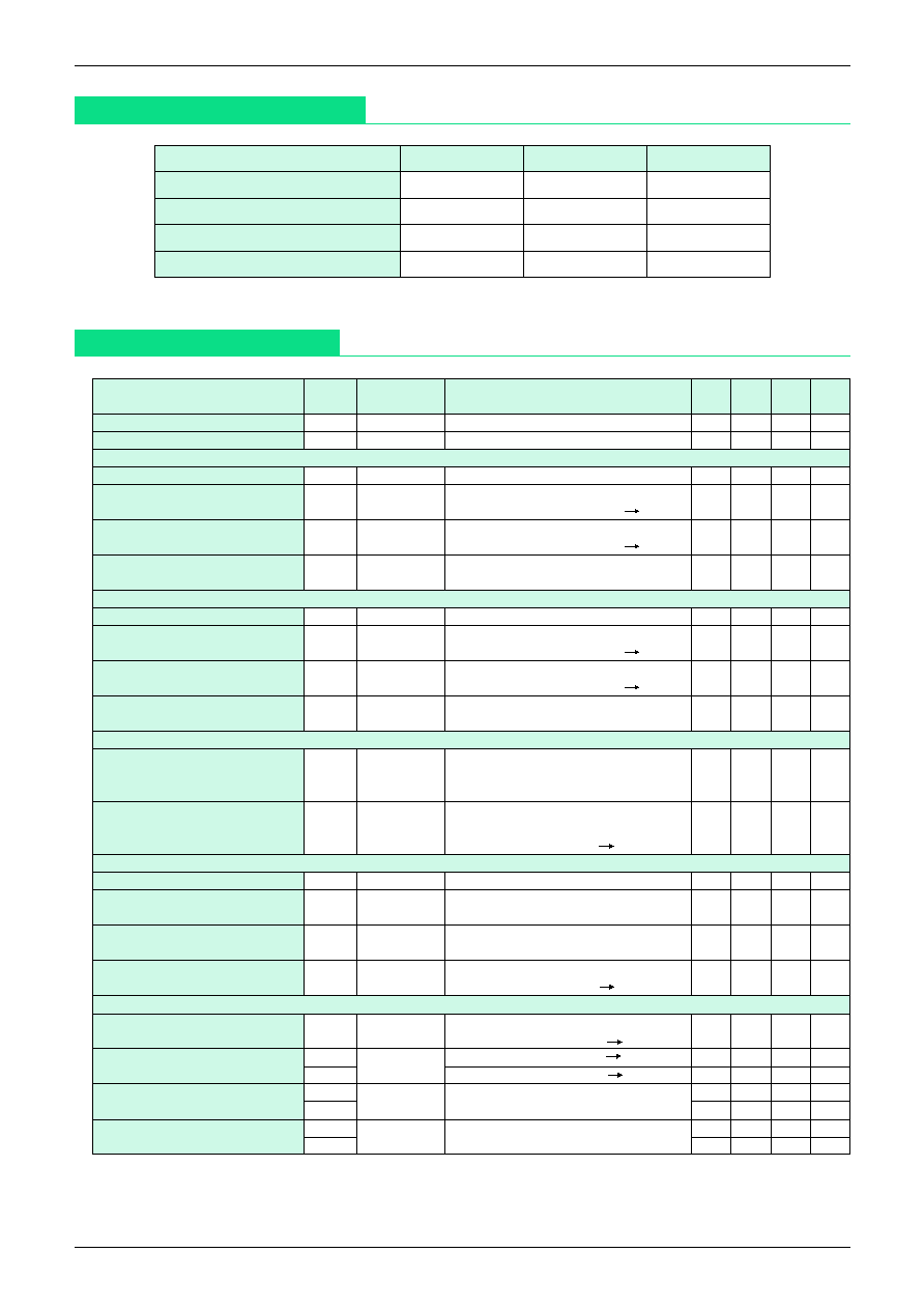
Absolute Maximum Ratings
(Ta=25∞C)
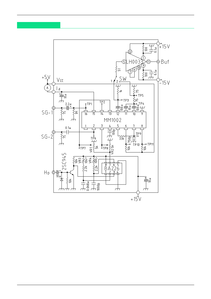
Electrical Characteristics
(Except where noted otherwise, Ta=25∞C, V
CC
=5.0V, pulse level 0V, short between V
CC
-Id pin)
Item
Symbol
Ratings
Units
Storage temperature
T
STG
-40~+125
∞C
Operating temperature
T
OPR
-20~+75
∞C
Power supply voltage
V
CC
7
V
Allowable loss
Pd
350
mW
Item
Symbol
Measurement
Measurement conditions
Min. Typ. Max. Units
circuit
Operating power supply voltage
V
CC
V
CC
4.7
5.0
5.3
V
Consumption current
Id
Id
18.0 25.0 mA
EVF output
Voltage gain
G
U
1
TP3
SG-1 sweep signal 1V
P-P
, 0.1MHz
-0.5
0.0
+0.5
dB
Differential gain
DG1
Buf
SG-1 staircase wave 1V
P-P
1
3
%
APL=10, 50, 90%, SW 1
Differential phase
DP1
Buf
SG-1 staircase signal 1V
P-P
1
3
deg
APL=10, 50, 90%, SW 1
Frequency characteristic
fc1
TP3
SG-1 sweep signal 1V
P-P
-1
0
1
dB
5MHz/0.1MHz
*
1
Video amp output
Voltage gain
G
U
2
TP4
SG-1 sweep wave 1V
P-P
, 0.1MHz
5.5
6.0
6.5
dB
Differential gain
DG2
Buf
SG-1 staircase wave 1V
P-P
1
3
%
APL=10, 50, 90%, SW 2
Differential phase
DP2
Buf
SG-1 staircase signal 1V
P-P
1
3
deg
APL=10, 50, 90%, SW 2
Frequency characteristic
fc2
TP4
SG-1 sweep signal 1V
P-P
-1
0
1
dB
5MHz/0.1MHz
*
1
Character addition
SG-1 staircase wave (no chroma signal) 1V
P-P
Character level
V
CL
TP4
H
D
horizontal sync signal
115
120
125
IRE
TP7 pulse level 5V
SG-1 staircase wave (no chroma signal) 1V
P-P
Input threshold voltage
V
TH
13
TP7
H
D
horizontal sync signal
0.7
1.4
2.1
V
TP7 pulse level L H
*
2
Chroma amp
Voltage gain
G
U
3
TP4
SG-2 sine wave 0.1V
P-P
, 0.1MHz
13.5 15.0 16.5
dB
Frequency characteristic
fc3
TP4
SG-2 sine wave 0.1V
P-P
-1
0
1
dB
5MHz/0.1MHz
*
1
Crosstalk
C
TP4
SG-2 sine wave 0.1V
P-P
, 4MHz
-60
-40
dB
TP8 pulse level 5V
*
3
Input threshold voltage
V
TH
3
TP8
SG-2 sine wave 0.1V
P-P
, 4MHz
0.7
1.4
2.1
V
TP8 pulse level L H
*
4
Sync separation
Sync separation level
V
SEPA
TP1
SG-1 staircase wave (no chroma signal) 1V
P-P
SG-1 SYNC level max min
*
5
55
110
165
mV
7PIN threshold voltage
V
TH
7
H
TP9
TP9 DC voltage 0V H
*
6
1.9
2.1
2.3
V
V
TH
7
L
TP9 DC voltage 5V L
*
6
1.1
1.3
1.5
V
Horizontal sync output voltage
V
OH
6
TP10
SG-1 staircase wave
4.8
5.0
V
V
OL
6
(no chroma signal) 1V
P-P
*
7
0.2
0.4
V
Vertical sync output voltage
V
OH
8
TP11
SG-1 staircase wave
4.8
5.0
V
V
OL
8
(no chroma signal) 1V
P-P
*
8
0.2
0.4
V

MITSUMI
Video Amplifier MM1002
Notes :
*
1
Frequency response fc1, fc2, fc3
For the same conditions as the G
U
1 measurement, given video output for 0.1MHz as V2, and for
5MHz as V2, F
C
1 is obtained as follows. The same applies for f
C
2 and f
C
3.
V2
f
C
1=20LOG dB
V1
*
2
Character addition ∑∑∑∑∑∑∑ input threshold voltage V
TH
13
For the same conditions as the V
CL
measurement, adjust VR1 to raise pulse level gradually, and
TP7 pulse level when a character signal is output on TP4 is V
TH
13.
*
3
Chroma amp ∑∑∑∑∑∑ crosstalk C
Given TP4 level when there is no pulse input as V3, and the level when pulse input exists as V4, C
is obtained as follows.
V4
C=20LOG dB
V3
*
4
Chroma amp ∑∑∑∑∑∑ input threshold voltage V
TH
3
For the same conditions as C measurement, adjust VR2 to raise TP8 level from 0V. The TP8 level
when TP4 level changes at pulse input is V
TH
3.
*
5
Sync separation ∑∑∑∑∑∑ sync separation level V
SEPA
Input a 1V
P-P
staircase signal (no chroma signal) to SG-1, and gradually shrink the sync signal.
TP1 sync level when TP10 horizontal sync signal starts to disappear is V
SEPA
.
*
6
Sync separation ∑∑∑∑∑∑ Pin 7 threshold voltage V
TH
7
H
, V
TH
7
L
Impress external DC voltage on TP9 and raise gradually from 0V. TP9 level when TP11 level goes
from high to low is V
TH
7
H
. Lower gradually from 5V. TP9 level when TP11 level goes from low to
high is V
TH
7
L
.
*
7
Sync separation ∑∑∑∑∑∑∑ horizontal sync output voltage V
OH
6, V
OL
6
TP10 high level when a 1V
P-P
staircase signal (no chroma signal) is input to SG-1 is V
OH
6, and low
level is V
OL
6.
*
8
Sync separation ∑∑∑∑∑∑ vertical sync output voltage V
OH
8, V
OL
8
TP10 high level when a 1V
P-P
staircase signal (no chroma signal) is input to SG-1 is V
OH
8, and low
level is V
OL
8.