MITSUMI
IC for Headphone Stereos MM1006
IC for Headphone Stereos
Monolithic IC MM1006
Outline
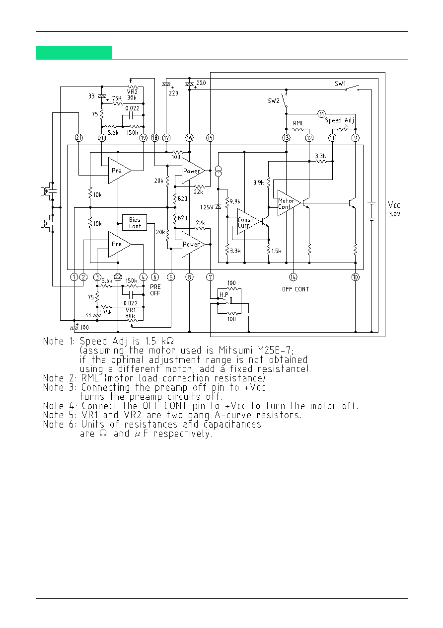
This IC was developed for use in headphone stereos, and incorporates the basic functions of a tape player as
well as dual preamp, power amp, and motor control circuits. It requires few external components and can be
used in a simple circuit configuration.
Features
1. Broad operating voltage range of 2.0 to 5.0 V (amp system operates to 1.8 V)
2. Simple circuit configuration
3. Power amp fixed at 28 dB
4. Ripple filter included
5. Provided with pin to turn off preamps
6. With noise from motor driving unit suppressed
Package
SDIP-22A (MM1006D)
SOP-24A (MM1006XF)
Absolute Maximum Ratings
Item
Symbol
Ratings
Units
Operating temperature
T
OPR
-20~+65
∞
C
Storage temperature
T
STG
-40~+125
∞
C
Power supply current
V
CC
-0.3~+7.5
V
Operating voltage
Vop
2.0~5.0
V
Power consumption
Pd
600 (SDIP-22A)
mW
450 (SOP-24A)
MITSUMI
IC for Headphone Stereos MM1006
Electrical Characteristics
(Except where noted otherwise,Vcc=3.0V, f=1kHz)
Item
Symbol
Measurement conditions
Min. Typ. Max. Units
Consumption current
I
CC
V
IN
=0V
5
10
mA
Preamp unit (Ta=25
∞
C)
Open-circuit gain
G
VO
Vo=-10dBm, R
L
=
, f=100Hz
72
dB
Closed-circuit gain
G
VC
Vo=-10dBm
40
42
44
dB
Maximum output voltage
Vom
THD=10%
0.30
0.45
V
Total harmonic distortion ratio
THD
V
OUT
=400mW, V
OUT
=-10dBm
0.05
0.5
%
Output noise voltage
Vno
V
IN
=0V, Rg=2.2k
, BPF=30Hz~20kHz
150
300
µA
Crosstalk between channels
C ∑ T
Rg=2.2k
30
dB
Output voltage with preamp off
Vooff
V
IN
=100mVrms
*
1
-50
dB
Output resistance with preamp off
Rooff
10
k
Input resistance with preamp off
Rioff
10
k
Measurement conditions: Preamp off pin: Open
*
1: Preamp off pin: Connect to V
CC
Power amp unit (Ta=25
∞
C)
Voltage gain
Gv
P
OUT
=5mW
26
28
30
dB
Voltage gain difference between channels
Gv
VR1, 2=max.
0
2
dB
Maximum output power I
Pom1
THD=10%, R
L
=32
20
28
mW
Maximum output power II
Pom2
THD=10%, R
L
=16
30
mW
Total harmonic distortion ratio
THD
P
OUT
=5mW
0.6
2.0
%
Output noise voltage
Vn
Rg=10k
0.25
1.0
mVrms
Crosstalk between channels
C ∑ T
P
OUT
=5mW
40
50
mVrms
Ripple rejection
RR
100Hz, 100mVp-p
40
50
dB
Noise of preamp + power amp
Vnto
V
IN
=0V, Rg=2.2k
, VR1, 2 : max.
6
9
mVrms
Measurement conditions: R
L
=16
Motor speed control unit (Ta=25
∞
C)
Consumption current
IMC
I
M
=0mA
3.0
5.0
mA
Startup current
IMS
500
mA
Reference voltage
Vref
Between RML-ADJ pins
0.72
0.80
0.87
V
Reference voltage fluctuation I
Vref1
V
CC
between 2.0 and 5.0V
*
2
0.05
%/V
Reference voltage fluctuation II
Vref2
I
M
between 25 and 250 mA
0.01
%/mA
Reference voltage fluctuation III
Vref3
Ta between -10 and 50
∞
C
0.01
%/
∞
C
Current coefficient
K
32
38
43
Current coefficient fluctuation I
K1
V
CC
between 2.1 and 5.0 V
0.5
%/V
Current coefficient fluctuation II
K2
I
M
between 25 and 250 mA
0.05
%/mA
Current coefficient fluctuation III
K3
Ta between -10 and 50
∞
C
0.02
%/
∞
C
Leakage current on forced off
IML
200
µA
Input resistance on forced off
Ricon
37
k
Measurement conditions: I
M
=100 mA Motor: M25E-5 (Mitsumi model)
*
2: Voltage fluctuation between motors
MITSUMI
IC for Headphone Stereos MM1006
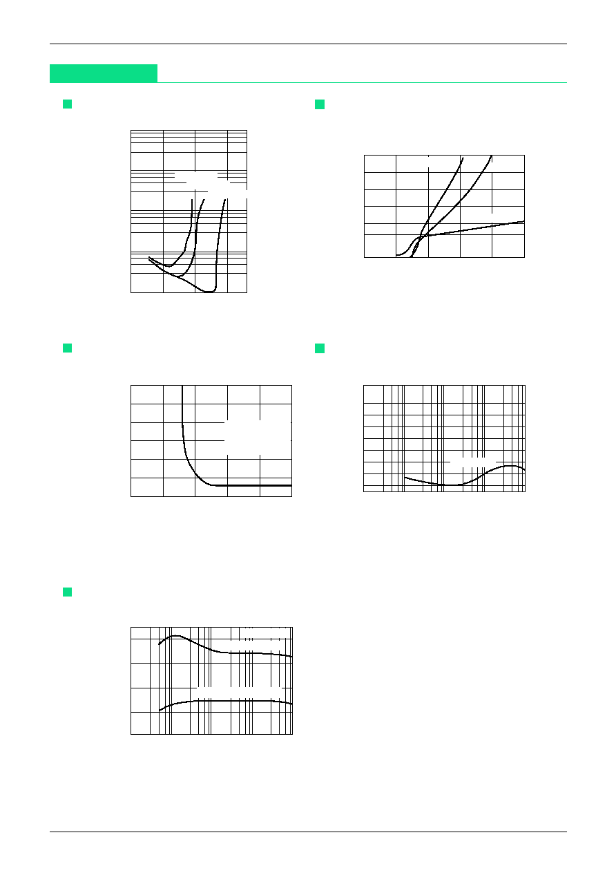
Characteristics
Preamp
THD-V
OUT
10.0
1.0
0.1
0.01
-30
-20
-10
0
Output voltage (dBm)
V
CC
=1.8V
V
CC
=2.0V
V
CC
=3.0V
Total harmonic distortion ratio (%)
P
OUT.
Power supply voltage (V)
1.0
2.0
3.0
4.0
5.0
0
6
4
2
8
10
12
40
50
60
30
20
10
I
CC
-V
CC
R
L
=16
R
L
=32
I
OC
(R
L
=16
)
Power supply output
(THD=10%) P
OUT
max.(mW)
No-load consumption current (mA)
Power amp
Power supply (V)
1.0
2.0
3.0
4.0
5.0
0
-10
-20
-30
-40
-50
-60
Ripple rejection-V
CC
F
R
=100Hz
V
R
=100mVrms
R
L
=16
Ripple rejection rate (dB)
Power amp
0
-10
-20
-30
-40
-50
-60
-70
10
100
Frequency (Hz)
1k
10k
100k
Crosstalk frequency
V
CC
=3.0V
Crosstalk (dB)
Voltage gain- Frequency
10
100
1k
10k
100k
Frequency (Hz)
60
40
20
0
80
TOTAL GAIN
POWER AMP GAIN
V
CC
=3.0V
Gain (dB)