MITSUMI
IC for DC Motor Control MM1038
IC for DC Motor Control
Monolithic IC MM1038
Outline
This IC is used to control the revolution rate of motors which can be controlled by low voltages. It can be
used to configure a high-precision FG motor using few external components. In particular, a unique new
circuit design with improved low-voltage operating characteristics enables configuration of sets such as
headphone stereos with auto-reverse functions which are unaffected by power supply voltage drops when the
motor is reversed, making them ideal for speed control of low-voltage DC motors.
Features
1. Operation at low voltages possible
2. Broad power supply voltage range
3. Small input current
4. Few external components, small package
5. Speed is easily changed over a wide range; accommodates two-speed operation
Package
SOP-8A (MM1038AF)
SOP-8D (MM1038CF)
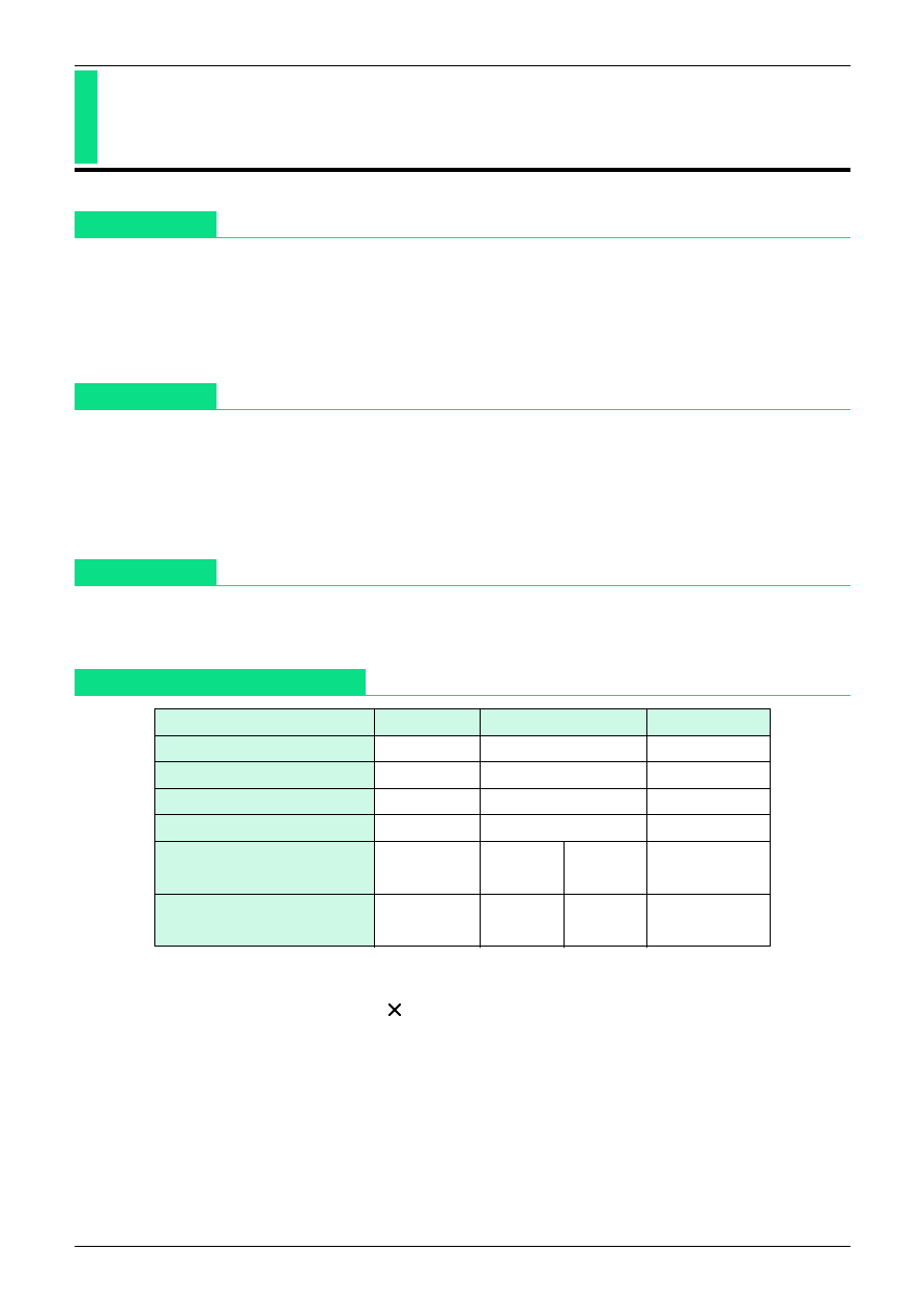
Absolute Maximum Ratings
Item
Symbol
Ratings
Units
Operating temperature
T
OPR
-10~+60
∞
C
Storage temperature
T
STG
-30~+125
∞
C
Power supply current
V
CC
-0.3~10
V
Output current
IL
700
mA
Power consumption I
*
1
Pd I
Ta=25
∞
C
Ta=40
∞
C
mW
340
290
Power consumption II
*
2
Pd II
Ta=25
∞
C
Ta=40
∞
C
mW
690
580
*
1: Power consumption I : Unit
*
2: Power consumption II : when mounted on board
(55.0 20.0 mm, t=0.8 mm, copper area 30%)
MITSUMI
IC for DC Motor Control MM1038
Electrical Characteristics
(Except where noted otherwise, Ta=25
∞
C)
Item
Symbol
Measurement conditions
Min. Typ. Max. Units
Consumption current
Id
A1
1.75
4.0
mV
Startup current
I
MS
A2 when R
V
is 1.5
500
mV
Reference voltage
VS
A1 when SW1 is off
90
100
110
mV
Reference voltage fluctuation I
VS1
VS fluctuation rate for V
CC
between 1.5 and
3.5 V with V
CC
=3.0 V as reference
0.1
0.5
%/V
Reference voltage fluctuation II
VS2
VS fluctuation rate for IM between 25 and
200 mA with IM=100 mA as reference
0.05
0.05 %/mA
Reference voltage fluctuation III
VS3
VS fluctuation rate for Ta between -10 and
as reference 60 ∞C with Ta=25∞C
0.01
%/
∞
C
Output saturation voltage
VoSAT
V2 SW2 on, when IM is 200mA
0.2
0.3
V
Bridge ratio
K
V4/V3
9.5
10
10.5
Bridge ratio fluctuation I
K1
K fluctuation rate for V
CC
between 1.5 and
3.5 V with V
CC
=3.0 V as reference
0.1
0.2
%/V
Bridge ratio fluctuation II
K2
K fluctuation rate for IM between 25 and
200 mA with IM=100 mA as reference
0.01
0.06 %/mA
Bridge ratio fluctuation III
K3
K fluctuation rate for Ta between -10 and
60 ∞C with Ta=25 ∞C as reference
0.01
%/
∞
C
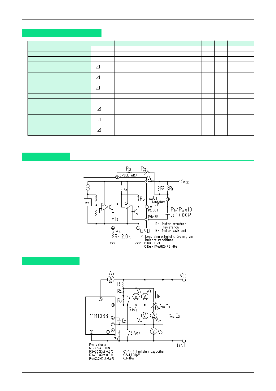
Block Diagram
Measuring Circuit
Measurement conditions: Except where noted otherwise,V
CC
=3.0 V, IM=100 mA, SW1=on, SW2=off