 | –≠–ª–µ–∫—Ç—Ä–æ–Ω–Ω—ã–π –∫–æ–º–ø–æ–Ω–µ–Ω—Ç: MM1373E | –°–∫–∞—á–∞—Ç—å:  PDF PDF  ZIP ZIP |
MITSUMI
For lithium ion battery protection (for double protection) MM1373
For lithium ion battery protection (for double protection)
Monolithic IC MM1373
Outline
This IC detects overcharging of lithium ion batteries. It is designed for use with three or four battery cells, and
detects battery voltages for each cell. An overcharge detection delay time can be set using an external
capacitor. The overcharge detection signal output is NPN open-collector, and goes low when overcharging is
detected. MM1451 is available for 1 ~ 3 cells. Overcharge detection signal output is PNP output, and output
goes high during detection.
Features
1. Consumption current
V
CEL
=3.8V
3.0µA typ.
2. Consumption current
V
CEL
=2.3V
0.3µA typ.
3. Input current between cell pins
V
CEL
=3.8V
±0.3µA max.
4. Overcharge detection voltage
A type
4.35V±50mV
5. Overcharge detection delay time
C
T
=0.22µF
1.5S typ.
6. Detection voltage can be changed to accommodate customer needs
Package
SOP-8C
SOP-8E
Applications
1. For 3 ~ 4 cell lithium ion batteries, for double protection.
Overcharge Detection ICs
MM1373
Detection voltage
Hysteresis
Rank A
4.350V
250mV
Rank C
4.225V
None
Rank D
4.130V
None
Rank E
4.450V
100mV
MITSUMI
For lithium ion battery protection (for double protection) MM1373
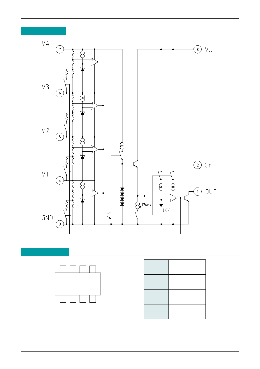
Pin Assignment
1
4
3
2
8
5
6
7
SOP-8C, SOP-8E
1
OUT
2
C
T
3
GND
4
V1
5
V2
6
V3
7
V4
8
V
CC
Block Diagram
MITSUMI
For lithium ion battery protection (for double protection) MM1373
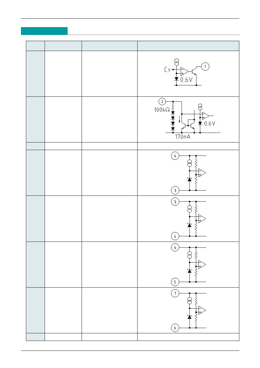
Pin Description
Pin no.
Pin name
Function
Internal equivalent circuit diagram
1
OUT
Reset output pin
2
C
T
Delay capacitance pin
4
V1
Cell 1 power supply
5
V2
Cell 2 power supply
6
V3
Cell 3 power supply
7
V4
Cell 4 power supply
8
V
CC
3
GND
Ground pin
MITSUMI
For lithium ion battery protection (for double protection) MM1373
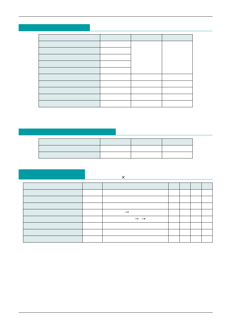
Absolute Maximun Ratings
Recommended Operating Conditions
Electrical Characteristics
(Except where noted otherwise, Ta=25∞C, V
CEL
=V4-V3=V3-V2=V2-
V1=V1-GND, V
CC
=4 V
CEL
) Models listed MM1373AF
*
1 V
CC
>
= V4 >
= V3 >
= V2 >
= V1 >
= -0.3
*
2: A current no greater than 100µA should be passed through pin Ct.
Item
Symbol
Ratings
Units
V
CC
input voltage
V
CC
V4 input voltage
*
1
V4
V3 input voltage
*
1
V3
-0.3~24
V
V2 input voltage
*
1
V2
V1 input voltage
*
1
V1
C
T
pin voltage
*
2
V
CT
-0.3~24
V
V
OUT
pin voltage
V
OUT
-0.3~24
V
Allowable loss
Pd
300
mW
Operating temperature
T
OPR
-20~+80
∞C
Storage temperature
T
STG
-40~+125
∞C
Item
Symbol
Ratings
Units
Input voltage between cells 1
Vop1
2.0~4.35
V
V
CC
input voltage
Vop2
4.0~18
V
Item
Symbol
Measurement conditions
Min. Typ. Max. Units
Consumption current 1
I1
V
CEL
=3.8V
3.0
6.0
µA
Consumption current 2
I2
V
CEL
=2.3V
0.3
0.5
µA
Pin I/O current between cells
I3
V
CEL
=3.8V (V4, V3, V2, V1 side)
±0.0
±0.3
µA
Overcharge detection voltage
V
S
V
CEL
=L H, Ta=-20~+70∞C
4.30
4.35
4.40
V
Hysteresis voltage
HSY
V
CEL
=L H L
0.20
0.25
0.30
V
Overcharge detection delay time
T
PLH
C
T
=0.22µF
1.0
1.5
2.0
S
Output voltage L
V
OL
I
L
=100µA
0.4
V
Output leakage current
I
LEAK
V
CEL
=3.8V, V
OUT
=24V
0.1
µA
MITSUMI
For lithium ion battery protection (for double protection) MM1373
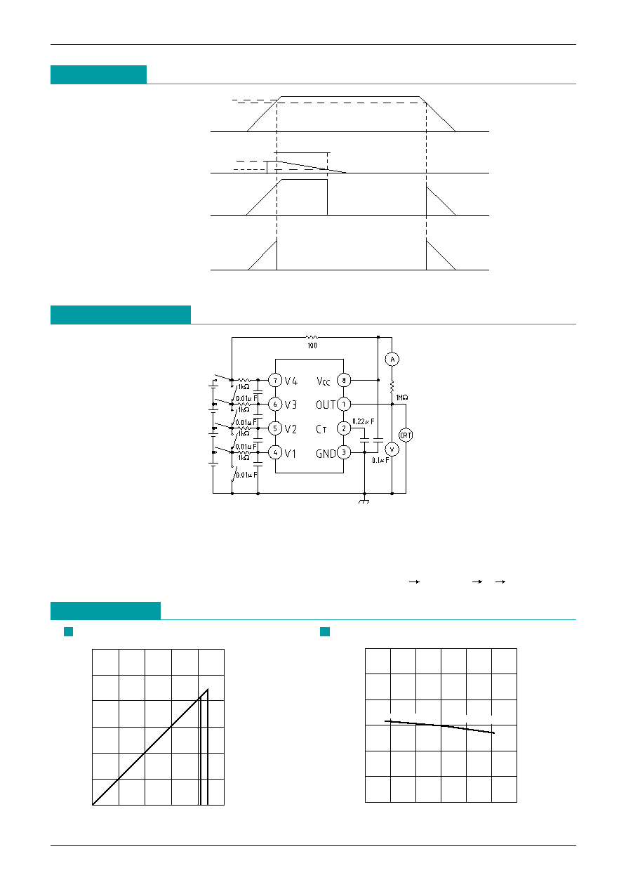
Timing Chart
4.35V
V1~V4
C
T
OUT
OUT
(When C
T
is open)
4.10V
1.80V
0.60V
1.5S
Application Circuits
Note : When pin Ct is shorted or left open, the output goes low when overcharging is detected.
Characteristics
1
0
1
2
3
4
5
6
2
3
4.10 4.35
Input voltage (No delay) (V)
Output voltage (V)
0.0
-25
25
75
0.5
1.0
1.5
2.0
2.5
3.0
Temperature (
∞
C)
-1100ppm
-2200ppm
Delay time (S)
Detection voltage
Output delay time
Note 1: By shorting each cell, two-, three- and four-cell series can be accommodated. A V4 cell should
always be connected. If the V4 cell is shorted, the chip may not function correctly.
Note 2: The input resistance for each cell should be 1k
or lower. Also, please select the appropriate value
for the external capacitor according to the usage environment.
Note 3: Connect in the following order when connecting the battery: GND V4 and V
CC
V2 V1 or V3.