MITSUMI
RGB Video Amplifier for Monitors MM1375
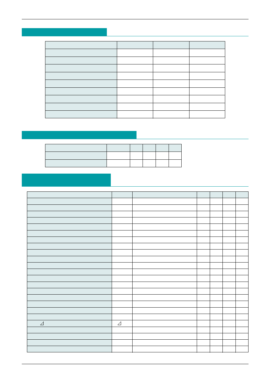
Absolute Maximum Ratings
(Ta=25∞C)
Item
Symbol
Ratings
Units
Storage temperature
T
STG
-40~+125
∞C
Operating temperature
T
OPR
-20~+80
∞C
Power supply voltage 1
V
CC
1
10
V
Power supply voltage 2
V
CC
2
15
V
Input voltage range
V
IN
GND <
= V
IN
<
= V
CC
1
V
Video output current
I
O
28
mA
Allowable loss
Pd
1.6
W
Electrostatic breakdown
2
kV
Pin temperature
265
*
∞C
Recommended Operating Conditions
(Ta=25∞C)
Item
Symbol
Min. Typ. Max. Units
Operating power supply voltage 1
V
CC
1
7.6
8.0
8.4
V
Operating power supply voltage 2
V
CC
2
7.6
12.6
V
Note : Solder for 10S
DC Electrical Characteristics
(Except where noted otherwise, Ta=25∞C, V
CC
1=8V, V
CC
2=8~12V,
V9=4V, V10=4V, V11=0V, V
C
-o=1.0V, V
DRV
=4V)
Item
Symbol
Measurement conditions
Min. Typ. Max. Units
Power supply current
I
CC
1
V
CC
1+V
CC
2
68
80
mA
Video amp input voltage
V
B
2.2
V
Video input resistance
R
B
100
k
Clamp gate input voltage L
V
CGL
0.8
1.2
V
Clamp gate input voltage H
V
CGH
1.6
2.0
V
Clamp gate input current L
I
CGL
V11=0V
-0.5
-5.0
µA
Clamp gate input current H
I
CGH
V11=8V
0.01
1.0
µA
Input charging current
I
IN+
0.75
1.0
mA
Input discharge current
I
IN-
-0.75 -1.0
mA
Clamp cap charge current
I
CL+
0.75
1.0
mA
Clamp cap discharge current
I
CL-
-0.75 -1.0
mA
Clamp cap bias discharge current
I
CLB
50
nA
Blanking gate input voltage L
V
BGL
0.8
1.2
V
Blanking gate input voltage H
V
BGH
1.6
2.0
V
Blanking gate input current L
I
BGL
V10=0V
-1.0
-5.0
µA
Blanking gate input current H
I
BGH
V10=8V
0.01
1.0
µA
Video output voltage L
V
OL
V
C-O
=0V
0.15
0.5
V
Video output voltage H
V
OH
V
C-O
=6V
5.0
5.5
V
Black level output voltage
V
O
V
C-O
=1V
1.0
V
Black level output voltage
V
O
V
C-O
=1V
±100
mV
Output blanking voltage
V
OBLK
V10=0V
100
300
mV
Contrast control input current
I9
V9=4V
190
µA
Drive control input current
I
DBV
V
DBV
=4V
190
µA
Cutoff control input current
I
C-O
V
C-O
=0~4V
-500
nA
MITSUMI
RGB Video Amplifier for Monitors MM1375
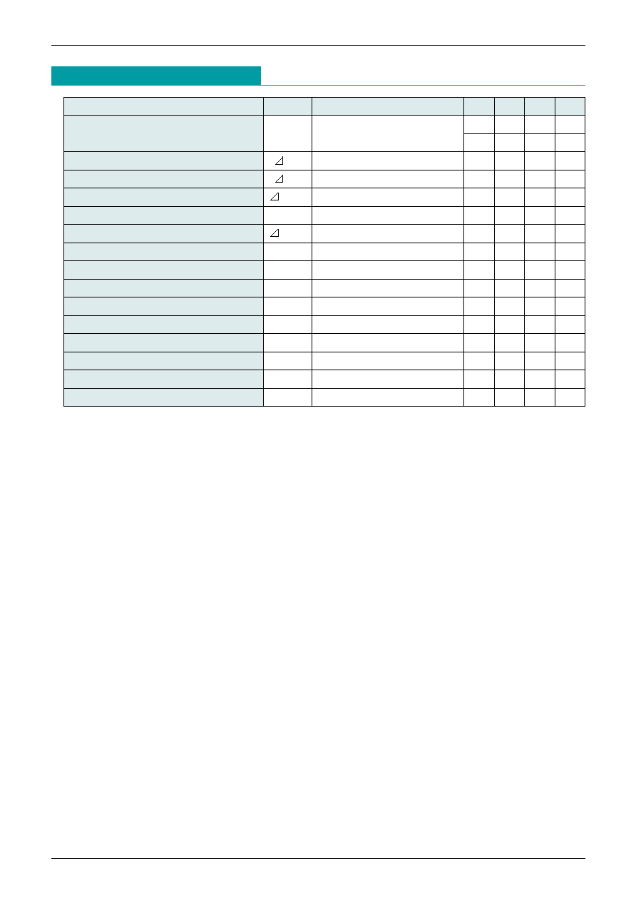
Item
Symbol
Measurement conditions
Min. Typ. Max. Units
Video amp gain
A
V
max.
V
IN
=635mV
P-P
, V9=4V
5.4
7.0
V/V
V
DRV
=4V
14.6
16.9
dB
Gain attenuation 1
A
V
1
V
IN
=635mV
P-P
, V9=2V
-6
dB
Gain attenuation 2
A
V
2
V
IN
=635mV
P-P
, V9=0.5V
-38
dB
Drive control range
A
VDRV
V
DRV
=0~4V, V9=4V
6
dB
Gain matching
A
VMAT
V9=V
DRV
=4V
0.3
dB
Gain change between amps
A
VMAT
V9=4~2V
0.1
dB
Video amp distortion
THD
V
OUT
=1V
P-P
1
%
Video amp frequency bandwidth
f
BW
V
OUT
=4V
P-P
, V9=V
DRV
=4V
100
MHz
Output rise time
tr
V
OUT
=4V
P-P
3
nS
Output fall time
tf
V
OUT
=4V
P-P
4
nS
Video amp isolation 1 (f
IN
=10kHz)
V
SEP
1
V9=4V
-70
dB
Video amp isolation 2 (f
IN
=10MHz)
V
SEP
2
V9=4V
-50
dB
Blanking output fall time
tr
V
OUT
=1V
P-P
7
nS
Blanking output fall time
tf
V
OUT
=1V
P-P
7
nS
Back-porch clamping pulse width
tpw
200
nS
AC Electrical Characteristics
(Except where noted therwise, Ta=25∞C, V
CC
1=8V, V
CC
2=8~12V)
