 | –≠–ª–µ–∫—Ç—Ä–æ–Ω–Ω—ã–π –∫–æ–º–ø–æ–Ω–µ–Ω—Ç: MM1412 | –°–∫–∞—á–∞—Ç—å:  PDF PDF  ZIP ZIP |

MITSUMI
Protection of Lithium-Ion Batteries MM1412
Protection of Lithium-Ion Batteries
Monolithic IC MM1412
Outline
This IC protects lithium ion batteries in the event of overcharge, overdischarge and overcurrent. It has the
following two functions: an overcurrent detection function that turns the external FET-SW off when a problem
occurs during charging, etc. and excess voltage is impressed on each battery for longer than a certain time,
and an overdischarge detection function that turns the external FET-SW off when battery voltage drops below
a certain voltage during discharge, in order to prevent battery overdischarge. When these functions operate,
the IC is put into low consumption current mode. It also has an overcurrent detection function that turns the
FET-SW off when excess current flows due to a short or the like.
Features
1. Consumption current (during overcharge)
V
CELL
= 4.5 R
OC
= 270 k
150µA typ.
2. Consumption current (normal)
V
CELL
= 3.5V
15µA typ.
3. Consumption current (during overdischarge)
V
CELL
= 1.9V
0.5µA typ.
4. Consumption current (during overdischarge)
V
CELL
= 1.0V
0.1µA max.
5. Overcharge detection voltage (Ta = 0∞C ~ 50∞C)
435 ± 25mV (detected for each cell)
6. Hysteresis voltage
220mV ± 50mV (detected for each cell)
7. Overdischarge detection voltage
2.30 ± 0.1V (detected for each cell)
8. Overdischarge release voltage
3.50V ± 0.2V (detected for each cell)
9. Overcurrent detection threshold
150mV ± 15mV
10. Reset after overcurrent detection
Load open
11. Operating limit voltage
0.9V max.
Package
VSOP-8A
SOP-8C
SOP-8E
MITSUMI
Model
Package
SOP-8C, E VSOP-8A
AW
4.350±0.025
C
220±50
2.3±0.1
3.5±0.2
150±15
CW
4.295±0.025
C
2.3±0.1
3.5±0.2
150±15
EF
EW
4.250±0.025
C
300±50
2.3±0.1
3.5±0.2
150±15
FW
4.250±0.025
C
220±50
2.0±0.1
3.1±0.2
150±15
GW
4.300±0.025
C
220±50
2.0±0.1
3.1±0.2
140±15
MM1412
HW
4.225±0.025
C
2.3±0.1
3.5±0.2
150±15
JW
4.250±0.025
C
150±50
4.5±0.2
150±15
KW
4.350±0.025
C
220±50
2.3±0.1
3.5±0.2
100±15
LW
4.125±0.025
C
2.3±0.1
3.5±0.2
150±15
MW
4.125±0.025
C
2.0±0.1
3.1±0.2
100±15
NW
4.190±0.025
C
2.0±0.1
3.1±0.2
100±15
PW
4.300±0.025
C
220±50
2.0±0.1
3.1±0.2
75±15
Overcharge
detection
voltage (V)
Overcharge
detection voltage
temperature
conditions
Overcharge
detection
hysteresis
voltage (V)
Overdischarge
detection
voltage (V)
Overdischarge
reset
voltage (V)
Overcurrent
detection
voltage (mV)
Series Table
Temperature conditions A: Ta=-25 ~ 75∞C, B: Ta=-20 ~ 70∞C, C: Ta=0 ~ 50∞C,
D: Ta=0 ~ 40∞C, E: Ta=-20 ~ 25∞C

MITSUMI
Protection of Lithium-Ion Batteries MM1412
MITSUMI
Block Diagram
Pin Assignment
1
4
3
2
8
5
6
7
VSOP-8A
1
OC
2
GD
3
CS
4
GND
5
TD
6
VL
7
V
CC
8
VH
Applications
1. Cell phone
2. Movie

MITSUMI
Protection of Lithium-Ion Batteries MM1412
Pin Description
Pin No. Pin name
Functions
Overcharge detection output pin
1
OC
PNPT
R
open collector output
Overcharge mode: ON
Normal mode, overdischarge mode, overcurrent mode: OFF
Discharge control FET (N-ch) control output pin
2
GD
Normal mod, overcharge mode: H
Overdischarge mode, overcurrent mode: L
Overcurrent detection input pin
3
CS
Monitors discharge current equivalently by the voltage drop between discharge control FET source
and drain. Stops discharge when voltage between CS pin and GND pin goes above overcurrent
detection threshold value, and holds until load is released.
4
GND
Ground pin, or lower cell load negative pole input pin.
5
TD
Overcharge detection dead time setting pin
Dead time can be set by adding a capacitor between TD and GND pins.
6
VL
Battery intermediate potential input pin
Connection pin for lower cell positive electrode side and upper cell negative electrode side.
7
V
CC
Power supply input pin
8
VH
Upper cell positive electrode input pin
Note: Mode Descriptions
(1) Overcharge mode
Either H cell or L cell battery voltage exceeds overcharge detection voltage. Overcharge detection
operation delay can be set by the dead time setting pin.
(2) Normal mode
Both H and L cell battery voltages exceed overdischarge detection voltage and are less than
overcharge detection voltage.
(3) Overdischarge mode
Either H or L cell battery voltage is less than overdischarge detection voltage.
Overdischarge detection dead time is set internally. Overdischarge mode is released when charging
causes voltage to rise above overdischarge detection voltage. Also, when battery voltage goes above
overdischarge release voltage, it resets without charging, but the value is set high. (This function is
included in case charging can not be detected. Also, this release voltage has a temperature coefficient
of -6mV/∞C.)
(4) Overcurrent mode
Voltage between CS and GND exceeds overcurrent detection voltage during discharge.

MITSUMI
Protection of Lithium-Ion Batteries MM1412
Pin Description
Pin No. Pin name
Equivalent circuit diagram
Pin No. Pin name
Equivalent circuit diagram
1
OC
5
TD
2
GD
6
VL
3
CS
8
VH

MITSUMI
Protection of Lithium-Ion Batteries MM1412
Recommended Operating Conditions
Electrical Characteristics
(Except where noted otherwise, Ta=25∞C) Models listed MM1412A
Item
Symbol
Ratings
Unit
Operating temperature
T
OPR
-20~+70
∞C
Operating power supply voltage
V
OP
+0.9~+18
V
Item
Symbol
Measurement conditions
Min. Typ. Max. Unit
Overcharge detection voltage
V
OC
Ta=0∞C~50∞C
4.325 4.350 4.375
V
Overcharge detection hysteresis voltage
V
OC
170
220
270
mV
Overdischarge detection voltage
V
OD
2.20
2.30
2.40
V
Consumption current 1
I
VH1
V
H
=V
L
=1.0V V
CS
=1.4V
0.1
µA
Consumption current 2
I
VH2
V
H
=V
L
=1.9V V
CS
=3.2V
0.5
0.8
µA
Consumption current 3
I
VH3
V
H
=V
L
=3.5V
15.0
20.0
µA
Consumption current 4
I
VH4
V
H
=V
L
=4.5V, R
OC
=270k
150
µA
VL pin input current
I
VL
V
H
=V
L
=3.5V
-0.3
0
0.3
µA
Overdischarge release voltage
V
DF
Discharge resume by voltage rise
3.30
3.50
3.70
V
GD pin H output voltage
V
GDH
V
H
=V
L
=3.5V, IL=-10µA
V
H
-0.3 V
H
-0.2
V
GD pin L output voltage
V
GDL
V
H
=V
L
=3.5V, IL=10µA
0.2
0.3
V
OC pin output current
I
OCH
V
H
=V
L
=4.5V
30
150
µA
Overcurrent detection threshold value
V
CS1
135
150
165
mV
Overcurrent short threshold value
V
CS2
When both battery pack pins are shorted
0.35
0.45
0.55
V
Overcurrent release
Load release: Load of 5MEG
or more between both battery pack pins
Overcurrent detection delay time 1
t
OC
1
7
12
18
ms
Overcurrent detection delay time 2
t
OC
2
*
1
30
100
µs
Overdischarge detection delay time
t
OD
8
13
20
ms
Overcharge detection dead time
t
OCH
C
TC
=0.18µF
0.5
1.0
1.5
s
Start-up voltage
V
ST
V
H
=V
L
=2.5V
-0.24 -0.12 -0.04
V
Note 1: Overcurrent short mode delay time (overcurrent delay time 2) is IC response speed.
In actual use, the time for discharging the discharge control FET gate capacity is added.
Also, when voltage change is large due to excess current, the IC internal bias current may turn off
temporarily, causing response time to lengthen. Select the time constant for the capacitor
connected to the power supply pin so that power supply fluctuation is more than 100µs/1V.
Note 2: Calculate overcharge dead time according to the following formula:
Overcharge detection dead time: t
ALM
- 5.55 C
TD
[s]
[C
TD
: external capacitor, Unit:µF]
Item
Symbol
Ratings
Unit
Storage temperature
T
STG
-40~+125
∞C
Operating temperature
T
OPR
-20~+70
∞C
Power supply voltage
V
CC
max.
-0.3~+18
V
OC pin impressed voltage
V
OC
max.
-0.6~V
CC
V
CS pin impressed voltage
V
CS
max.
-0.6~V
CC
V
Allowable loss
Pd
300
mW
Absolute Maximum Ratings

MITSUMI
Protection of Lithium-Ion Batteries MM1412
MITSUMI
Measuring Circuit
Measuring Circuit 1
(V
OC
, V
OC
, V
OD
, V
DF
, V
ST
, V
CS
, I
DCH
, V
GDH
, V
GDL
)
Measuring Circuit 2
(t
OC
, t
OD
, t
OCH
)
Note :
0.2V
CS
GD
0V
t OC
t OC
2.5V
2.0V
V
L
GD
1V/100
µ
S
V
OD
t OCH
4.5V
4.0V
OC
V
L
1V/100
µ
S
V
OC
MITSUMI
Protection of Lithium-Ion Batteries MM1412
MITSUMI
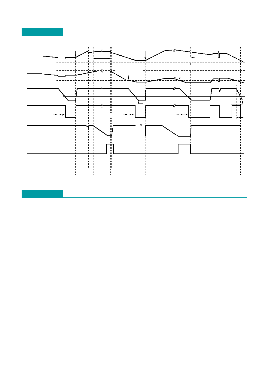
Timing Chart
Description
V
H
V
H
Dischage
control
dead time
setting
GD
TD
OC
Overcharge
Overdischarge
Overcharge
Overdischarge
Gate off
Keep cirquit
Over current
dead time
Open load
Overcharge
Over load
Charge sensing
dead time
Overdischarge
dead time
HI-impedance
Power down
Power
down
Short load
Overdischarge
detection
Overdischarge
Keep overcharge
Overdischarge
dead time
This IC is a lithium ion battery (2-cell in-series type) protection IC. It has built-in overcharge detection,
overdischarge detection and overcurrent detection circuits, and controls the FET (external N-MOS FET) that
controls charge and discharge.
The operation modes can be divided broadly into four, as follows.
1) Overcharge mode
The battery voltage of either the H or L cell goes above overcharge detection voltage. Detection operation
delay for overcharge detection can be set with the dead time setting pin.
2) Normal mode
The battery voltage of both H and L cells is above overdischarge detection voltage and below overcharge
detection voltage.
3) Overdischarge mode
The battery voltage of either the H or L cell drops below overdischarge detection voltage. Dead time for
overdischarge detection is set internally. Overdischarge mode is released when charging takes place and
the voltage goes above overdischarge detection voltage. Also, reset will occur even without charging if
battery voltage goes above overdischarge release voltage, but the set value is high. (This function is
provided as a measure for cases when charging can not be detected. Further, this release voltage has a
temperature coefficient of -6mV/∞C.)
4) Overcurrent mode
The voltage between CS-GND goes above overcurrent detection voltage during discharge.

MITSUMI
Protection of Lithium-Ion Batteries MM1412
Characteristics
0.001
0.01
0.1
0.001
0.01
0.1
1
External capacitance (C
TD
)
Overcharge detection time (S)
Overcharge Detection Time (Dead Time)
Note: Dead time can be calculated according to the following formula:
t
OC
=5.55 C
TD
[S]
t
OC
=Overcharge Detection Time
C
TD
=External Capacitor∑∑∑Unit : µF
The above specifications are representative, and are not guaranteed values.
Application Circuit
Note: Applicable circuits shown are typical examples provided for reference purposes. Mitsumi cannot
assume responsibility for any problems arising out of the use of these circuits or for any infringement of
third party patent and other right due to same.