 | –≠–ª–µ–∫—Ç—Ä–æ–Ω–Ω—ã–π –∫–æ–º–ø–æ–Ω–µ–Ω—Ç: MM1431AN | –°–∫–∞—á–∞—Ç—å:  PDF PDF  ZIP ZIP |
MITSUMI
Precision Adjustable Shunt Regulator MM1431 AT/AN
Precision Adjustable Shunt Regulator
Monolithic IC MM1431 AT/AN
Outline
The MM1431AT/AN is 3-termial adjustable shunt regulator, which provides a highly accurate 0.8% bandgap
reference voltage. The output voltage can be adjusted to any value between reference voltage V
REF
and 35
volts with two external resistors. Moreover, there are a lot of ranges of the application as a zener diode
besides the replacement is possible because it has steep turn-on characteristics.
Features
1. Reference voltage tolerance
V
REF
=2.495V±0.8%
2. Output voltage can be adjusted
V
REF
Vo
35V
3. Low Dynamic Output Impedance
Z
KA
<
0.2
typ.
Package
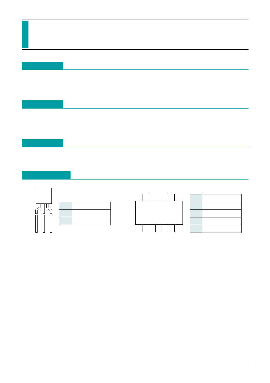
TO-92
SOT-25
Pin Assignment
1
2
3
TO-92
1
Reference
2
Anode
3
Cathode
1
3
5
2
4
SOT-25
(TOP VIEW)
1
NC
2
SUB
3
Cathode
4
Reference
5
Anode
note:The second terminal is SUB, so connect the terminal to GND.
MITSUMI
Precision Adjustable Shunt Regulator MM1431 AT/AN
Absolute Maximum Ratings
(Ambient Temperature, Ta=25∞C)
Item
Symbol
Ratings
Unit
Operating Temperature
T
OPR
-30~+85
∞C
Storage Temperature
T
STG
-40~+125
∞C
Cathode to Anode voltage
V
KA
35
V
Cathode current
I
K
-100~100
mA
Reference input current
I
REF
-0.05~10
mA
Allowable loss
Pd
500 (TO-92)
150 (SOT-25)
mW
Recommended Operating Conditions
(Ambient Temperature, Ta=25∞C)
Cathode to Anode voltage
V
KA
V
REF
~35
V
Cathode current
I
K
0.6~50
mA
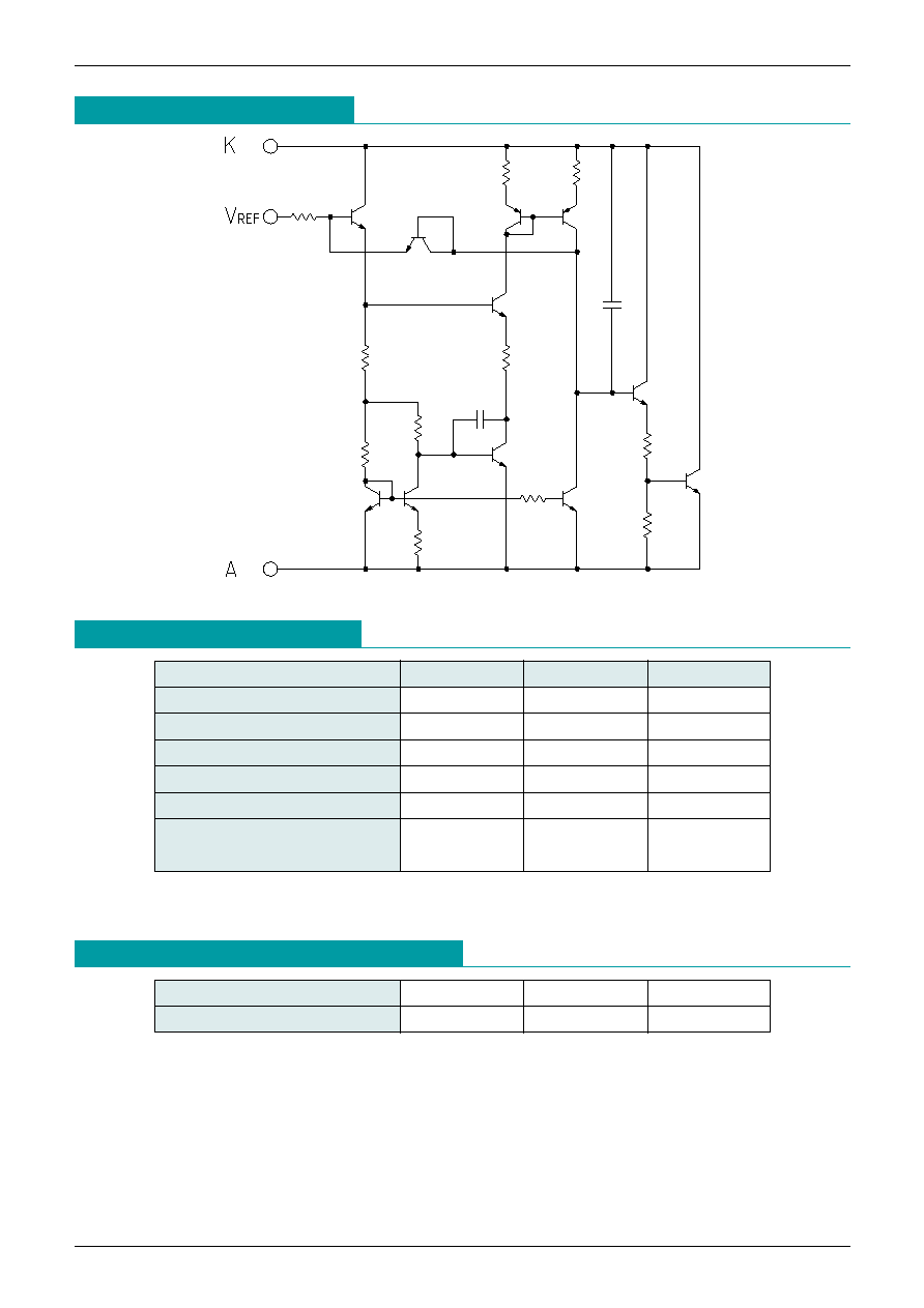
Equivalent Circuit Diagram
MITSUMI
Precision Adjustable Shunt Regulator MM1431 AT/AN
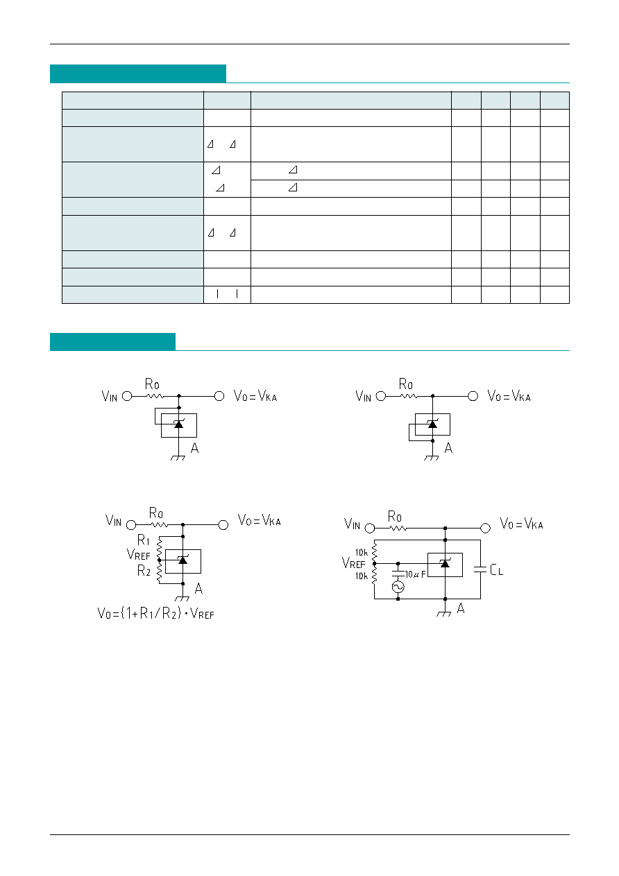
Measuring Circuit
Electrical Characteristics
(Ambient Temperature, Ta=25∞C)
Item
Symbol
Measurement conditions
Min. Typ. Max. Unit
Reference voltage
V
REF
V
KA
=V
REF
, I
K
=10mA
2.475 2.495 2.515
V
Reference voltage deviation
over temperature range
V
REF
/ Ta
V
KA
=V
REF
, I
K
=10mA Ta=-30~+85∞C
±10
mV
Lord regulation
V
REF
V
KA
=V
REF
~10V I
K
=10mA
-1.4
-2.7 mV/V
/ V
KA
V
KA
=10V~35V I
K
=10mA
-1
-2
mV/V
Reference input current
I
REF
I
K
=10mA R
1
=10K, R
2
=
1
4
µA
Reference input current deviation
over temperature range
I
REF
/ Ta
I
K
=10mA R
1
=10K, R
2
=
Ta=-30~+85∞C
±0.5
µA
Minimum Cathode Current
I
K
min.
V
KA
=V
REF
0.3
0.6
mA
Off-state Cathode Current
I
OFF
V
KA
=35V, V
REF
=0V
0.1
1.0
µA
Dynamic Impedance
Z
KA
V
KA
=V
REF
, f <
= 1kHz I
K
=1~50mA
0.2
0.5
(1) V
KA
=V
REF
(2) V
KA
>
= V
REF
Vo=V
KA
=V
REF
(3) I
OFF
(4) Open Loop Voltage Gain
MITSUMI
Precision Adjustable Shunt Regulator MM1431 AT/AN
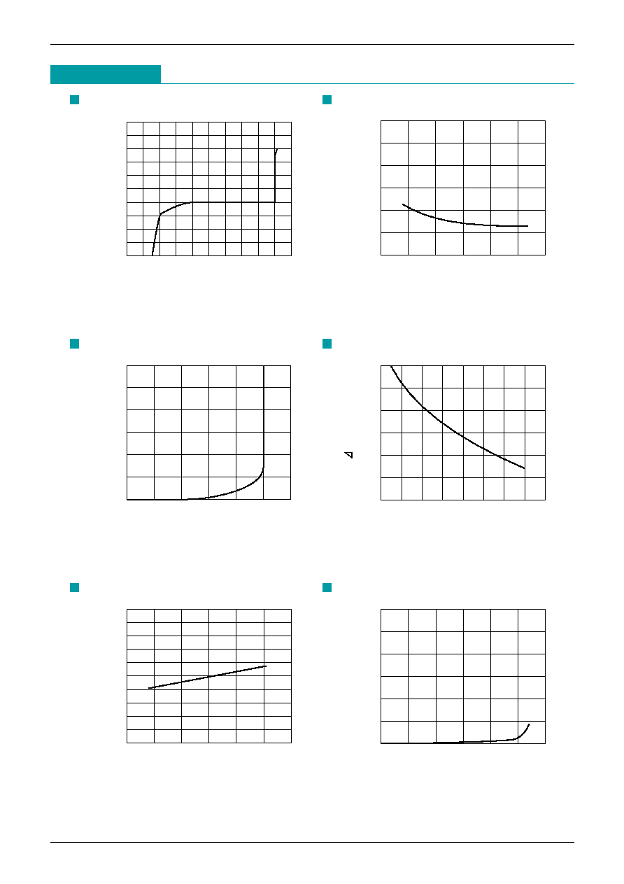
High Voltage Operating Characteristics
Reference Input Current
-100
3
1
-1
2
0
-2
Cathode Voltage V
KA
(V)
0
-25
-50
-75
25
100
75
50
125
150
Cathode Current I
K
(mA)
0
100
50
-25
75
0
25
-50
Ambient Temperature Ta (
∞
C)
2
1.5
1
0.5
2.5
3
Reference Input Current IRef (
µ
A)
Low Current Operating Characteristics
0
3
2
1
0
Cathode Voltage V
KA
(V)
0.8
0.6
0.4
0.2
1.0
1.2
Cathode Current I
K
(mA)
Reference Voltage
Reference Voltage
-30
40
20
5
35
30
25
10
15
0
Cathode Voltage V
KA
(V)
-10
-15
-20
-25
-5
0
Voltage Changed Portion
VRef (mV)
2.40
100
50
-25
75
0
25
-50
Ambient Temperature Ta (
∞
C)
2.48
2.46
2.44
2.42
2.50
2.56
2.54
2.52
2.58
2.60
Reference Voltage VRef (V)
Off State Leakage
0
100
50
-25
75
0
25
-50
Ambient Temperature Ta (
∞
C)
0.05
0.20
0.15
0.10
0.25
0.30
Off-state Cathode Current
I
OFF
(mA)
Characteristics
MITSUMI
Precision Adjustable Shunt Regulator MM1431 AT/AN
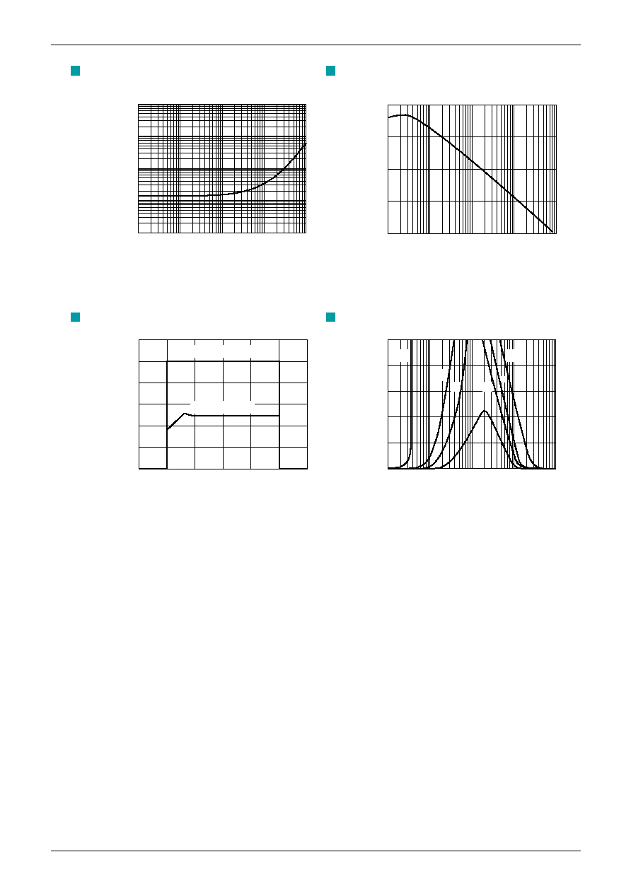
Dynamic Output Impedance
Open loop Voltage Gain V
KA
=5V
0.01
1M
10k
100k
1k
100
Frequency f (Hz)
10
1
0.1
100
Dynamic Impedance
(Z
KA
) (
)
-20
10M
100k
1M
10k
1k
Frequency f (Hz)
40
20
0
60
Open Loop Voltage Gain
A
V
(dB)
Pulse Response
0
6
2
4
5
3
1
0
Time t (
µ
S)
5
4
3
2
1
6
Input Voltage
Output Voltage
Input And Output Voltage
V
IN
V
OUT
(V)
Stability Boundary Conditions
0
10
0.1
1
0.01
00.1
Load Capacitance C
L
(
µ
F)
80
60
40
20
100
Cathode Current I
K
(mA)
a
a
b
b
c
c
d
Notes concerning stability operation region
The MM1431AT/AN requires external capasitors for regulator stability. These capacitors must be correctly
selected for good performance.
a: V
KA
=VREF b: V
KA
=5V C: V
KA
=10V
d: V
KA
=15V
Cathode voltage temperature Ta=25∞C
I
KA
=10mA C
L
=: Ceramic capacitor


