 | –≠–ª–µ–∫—Ç—Ä–æ–Ω–Ω—ã–π –∫–æ–º–ø–æ–Ω–µ–Ω—Ç: MM1437 | –°–∫–∞—á–∞—Ç—å:  PDF PDF  ZIP ZIP |

MITSUMI
Regulator+Reset IC MM1437
Regulator+Reset IC
Monolithic IC MM1437
Outline
This IC combines a low saturation 5V regulator, adapted for low power consumption, and a reset function
(regulator output monitoring), for which there is significant market need, that uses the built-in 4.2V detection
delay circuit.
Features
1. Small input/output voltage difference
0.25V typ.
2. High input voltage
18V max.
3. Internal thermal shutdown circuit.
4. Internal current-limiting circuit.
5. Adjustment-free reset detection voltage
4.2V typ.
6. Easy to set delay time from voltage detection to reset release.
Package
SOP-7
SIP-5
Applications
Pin Assignment
TV, monitors, air conditioners, others.
MITSUMI
1
4
2
3
7
6
5
SOP-7
SIP-5
1
2
3
4
5
1
GND
2
RESET
---------------------------------------------------------------------------------------
3
Cd
4
V
IN
5
V
OUT
6
GND
7
N.C
1
___
RESET
2
Cd
3
V
IN
4
V
OUT
5
GND
MITSUMI
Regulator+Reset IC MM1437
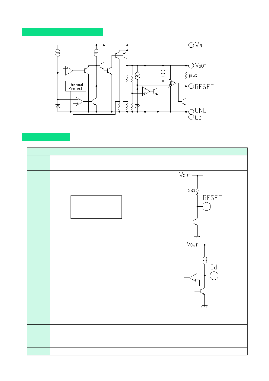
Equivalent Circuit Diagram
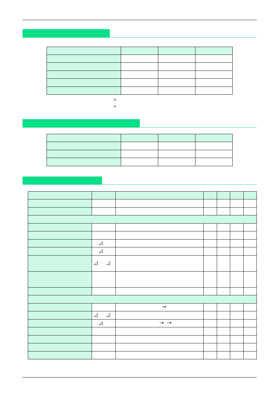
Pin Description
Pin No.
Pin name
Functions
Equivalent circuit diagram
1 (SOP-7)
GND
GND pin
5 (SIP-5)
2 (SOP-7) RESET
------------------------------------------------------------------------------
Output pin voltage detection output
1 (SIP-5)
V
OUT
pin voltage detection output pin
RESET
------------------------------------------------------------------------------
pin logic
3 (SOP-7)
Cd
Delay time capacitor pin
2 (SIP-5)
t
PLH
= 100000 ∑ C
t
PLH
: transmission delay time [S]
C: capacitor value [F]
4 (SOP-7)
V
IN
Voltage supply input pin
3 (SIP-5)
5 (SOP-7)
V
OUT
Regulator output pin
4 (SIP-5)
6 (SOP-7)
GND GND
pin
7 (SOP-7)
N.C
≠≠≠
RESET
V
OUT
<Vs
L
V
OUT
>Vs
H
RESET
------------------------------------------------------------------------------
pin output delay time
can be set by the capacitance
connected to the Cd pin.
MITSUMI
Regulator+Reset IC MM1437
Absolute Maximum Ratings
MITSUMI
Recommended Operating Conditions
Item
Symbol
Ratings
Unit
Operating temperature
T
OPR
-20~+85
∞C
Storage temperature
T
STG
-40~+125
∞C
Supply voltage
V
CC
-0.3~+18
V
Output current
I
OUT
200
mA
Power dissipation
Pd
650
*
mW
Item
Symbol
Ratings
Unit
Operating temperature
T
OP
-20~+85
∞C
Output current
I
OP
0~150
mA
Operating voltage
V
OP
2~16
V
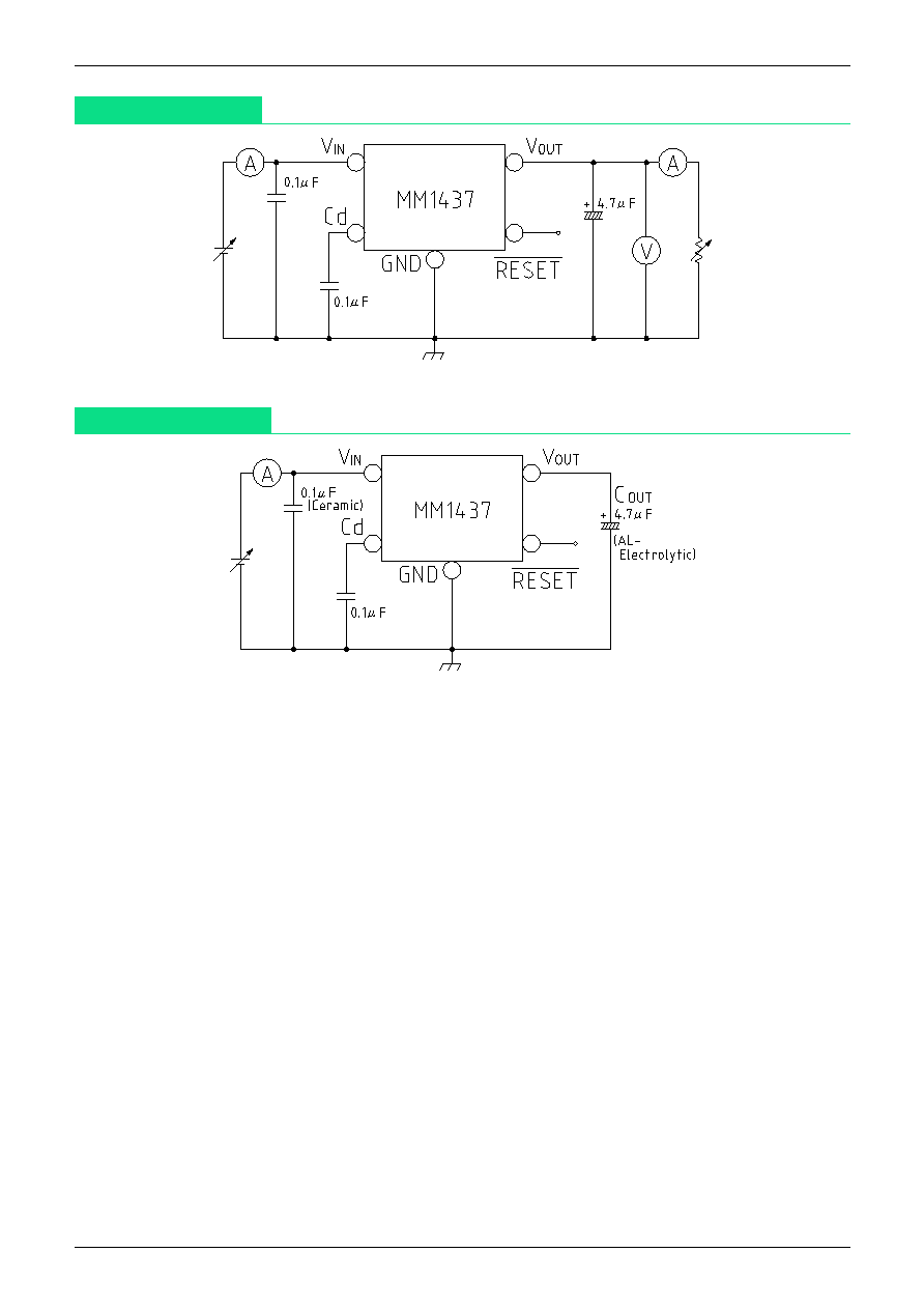
Electrical Characteristics
(Except where noted otherwise, Ta=25∞C)
Item
Symbol
Measurement conditions
Min. Typ. Max. Unit
No-load input current 1
Iccq1
V
IN
=6V I
OUT
=0mA 400
800
µA
No-load input current 2
Iccq2
V
IN
=4V I
OUT
=0mA 2.5
mA
Regulator
Output voltage
V
OUT
V
IN
=6V I
OUT
=30mA
4.90
5.00
5.10
V
Input-output differential voltage
Vi0
V
IN
=4.8V I
OUT
=150 mA
0.25
0.50
V
Line regulation
V1
V
IN
=6V~10V I
OUT
=30mA
10
30
mV
Load regulation
V2
V
IN
=6V I
OUT
=0~150mA
40
80
mV
Vo temperature
V
OUT
/ T
Tj=-20~+85∞C
coefficient
*
1
V
IN
=6V I
OUT
=30mA
100
ppm/∞C
Ripple rejection
*
1
RR
V
IN
=6V f=120Hz
V
RIPPLE
=1V
P-P
, I
OUT
=30mA
50
60
dB
Output noise voltage
*
1
Vn
V
IN
=6V, f=20~80kHz I
OUT
=30mA
200
400
µVrms
Reset
Detecting voltage
VS
V
IN
=H L
4.03
4.2
4.37
V
Vs temperature coefficient
*
1
VS/ T
Tj=-20~+85∞C
100
ppm/∞C
Hysteresis voltage
VS
V
OUT
=H L H
25
50
100
mV
Low-level output voltage
V
OL
V
OUT
=3.9V
100
200
mV
RESET
--------------------------------------------------------------------------------
delay time
t
PLH
Cd=0.1µF
5
10
15
mS
"L" transmission delay time
*
1
t
PHL
Cd=0.1µF
30
90
µS
Threshold operating voltage
V
OPL
VOL=0.4V
0.65
0.85
V
Note:
*
When mounted on a 55 20 mm paper phenol board (SOP-7)
When mounted on a 45 45 mm paper phenol board (SIP-5)
Note 1: design guaranteed
MITSUMI
Regulator+Reset IC MM1437
MITSUMI
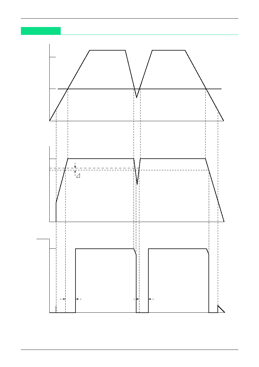
Measuring Circuit
Application Circuit
Note 1 : This regulator is not internally compensated and thus requires an external output-capacitor (C
OUT
) for
stability.
Note 2 : RESET
-
-----------------------------------------------------------------------------------------------------------------------
-terminal with a built-in pull-up resistance (10k
).
MITSUMI
Regulator+Reset IC MM1437
MITSUMI
Timing Chart
t
PLH
t
PLH
0V
5V
0V
VS
5V
0V
5V
10V
V
IN
V
OUT
RESET
VS
MITSUMI
Regulator+Reset IC MM1437
MITSUMI
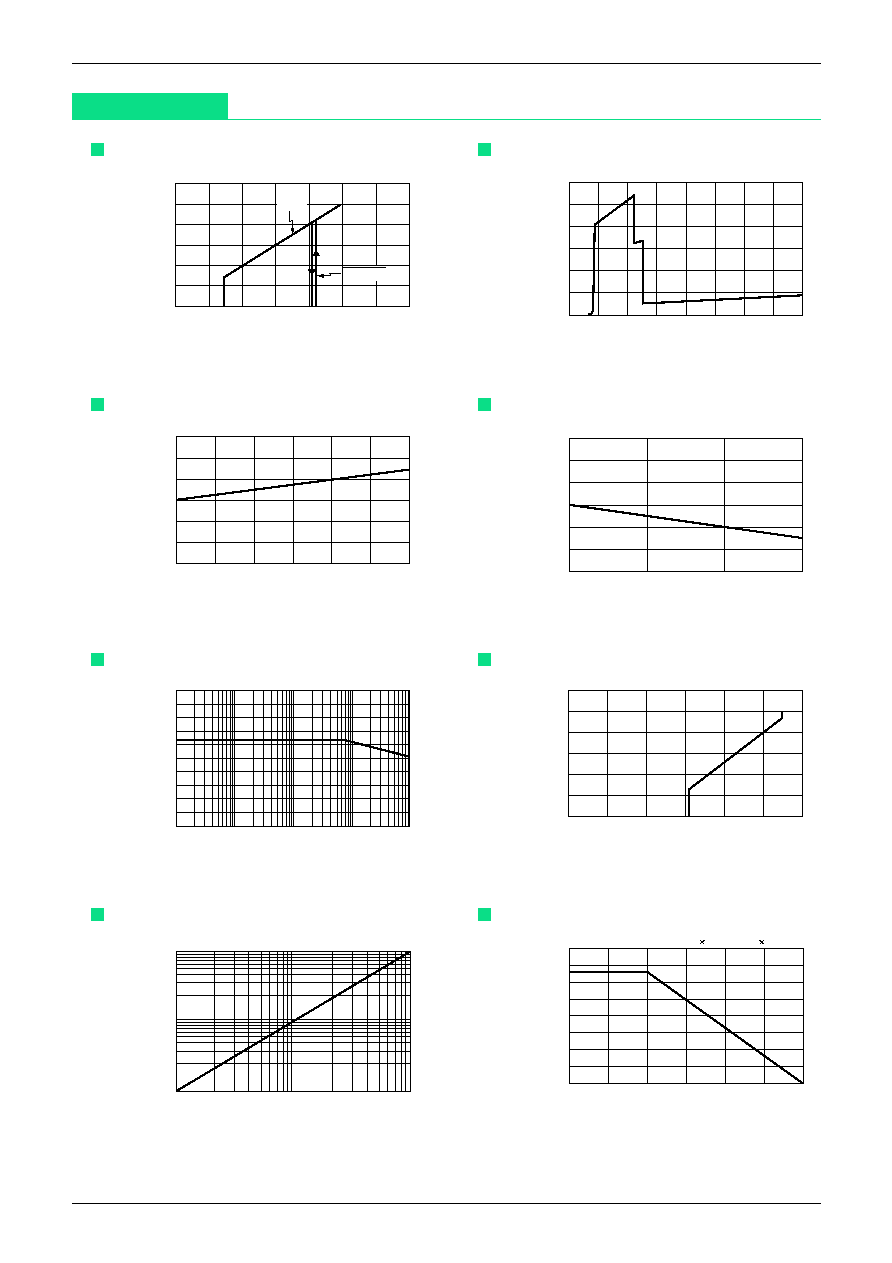
Characteristics
Detection voltage (I
OUT
=0mA)
Input Voltage (V)
6
5
4
3
2
1
0
0
1
2
3
4
5
6
7
V
OUT
RESET
Output voltage (V)
Quiescent current (I
OUT
=0mA)
Input Voltage (V)
3
2.5
2
1.5
1
0.5
0
0
2
4
6
8
10
12
14
16
Quiescent current (mA)
Line regulation
Input voltage (V)
30
20
10
0
-10
-20
-30
4
6
8
10
12
14
16
Line regulation (mV)
Load regulation
Output current (mA)
60
40
20
0
-20
-40
-60
0
50
100
150
Load regulation (mV)
Ripple rejection
Frequency (H
Z
)
100
90
80
70
60
50
40
30
20
10
0
10
100
1000
10000
100000
Ripple rejection (dB)
Current limit
Output current (mA)
6
5
4
3
2
1
0
0
50
100
150
200
250
300
Output voltage (V)
RESET delay time
Cd-capacitor (
µ
F)
100
10
1
0.01
0.1
1
Deyal time (mS)
Allowable loss
Temperature (
∞
C)
800
700
600
500
400
300
200
100
0
-25
0
25
50
75
100
125
Allowable loss (mW)
On board 55
22mm (SOP)/45
45mm (SIP)


