 | –≠–ª–µ–∫—Ç—Ä–æ–Ω–Ω—ã–π –∫–æ–º–ø–æ–Ω–µ–Ω—Ç: MM1446 | –°–∫–∞—á–∞—Ç—å:  PDF PDF  ZIP ZIP |
MITSUMI
Lithium Ion Battery Protection (for 1-cell in series) MM1446
Lithium Ion Battery Protection (for 1-cell in series)
Monolithic IC MM1446
Outline
This IC is a lithium ion battery protection IC that adds control using a fuse to the method of overcurrent
detection control used in the familiar MM1301 series. An OSI pin (charge control pin) also has been provided.
Package
VSOP-8B
Features
1. Overcharge detection voltage
Ta = 0 ~ +50∞C
V
CEL
±30mV
2. Overcharge detection dead time
C
TD
= 0.1µF
1.0 sec
3. Consumption current (normal mode V
CEL
= 3.5V)
14µA typ.
4. Consumption current (overdischarge mode V
CEL
= 1.9V)
0.2µA typ.
5. Overcurrent protection release
Load open: between both ends of battery pack
load of 500M
or higher
Applications
1-Cell Protection ICs
Temperature conditions A : Ta=25 ~ 75∞C, B : Ta=-20 ~ 70∞C, C : Ta=0 ~ 50∞C,
D : Ta=0 ~ 40∞C, E : Ta=-20 ~ 25∞C
Lithium ion battery packs (for battery protection)
*
The series will continue to be expanded.
*
Overcharge and overdischarge voltages and overcurrent detection voltage can
be changed at the customer's request.
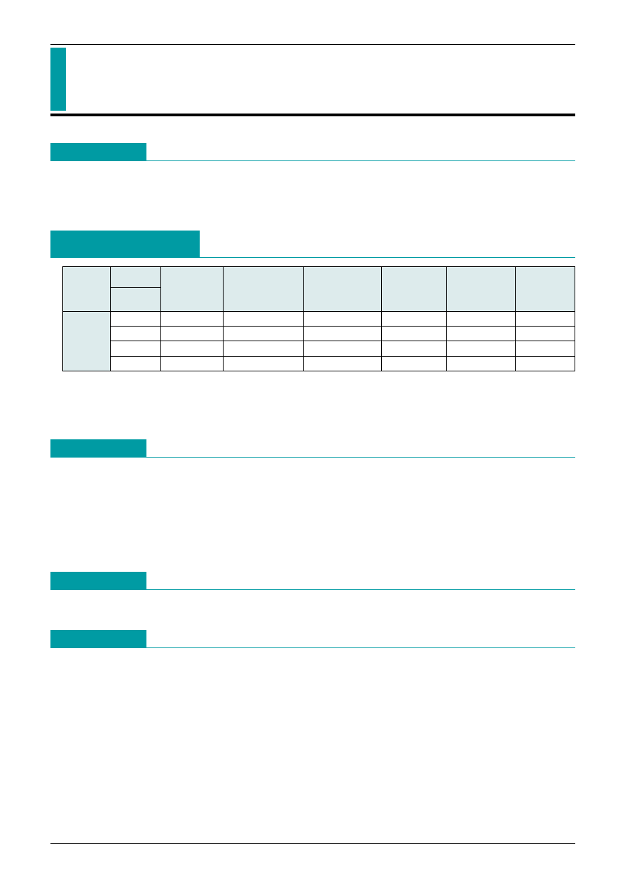
Model
Package
VSOP-8B
BW
4.270±0.030
C
100±30
2.55±0.05
3.70
39.0±4.5
MM1446
CW
4.270±0.030
C
100±30
2.55±0.05
3.70
52.0±4.5
DW
4.180±0.030
C
110±30
2.50±0.05
3.10±0.078
39.0±4.5
EW
4.280±0.030
C
110±30
2.50±0.05
3.10±0.078
39.0±4.5
Overcharge
detection
voltage (V)
Overcharge
detection voltage
temperature
conditions
Overcharge
detection
hysteresis
voltage (V)
Overdischarge
detection
voltage (V)
Overdischarge
resumption
voltage (V)
Overcurrent
detection
voltage (mV)
MITSUMI
Lithium Ion Battery Protection (for 1-cell in series) MM1446
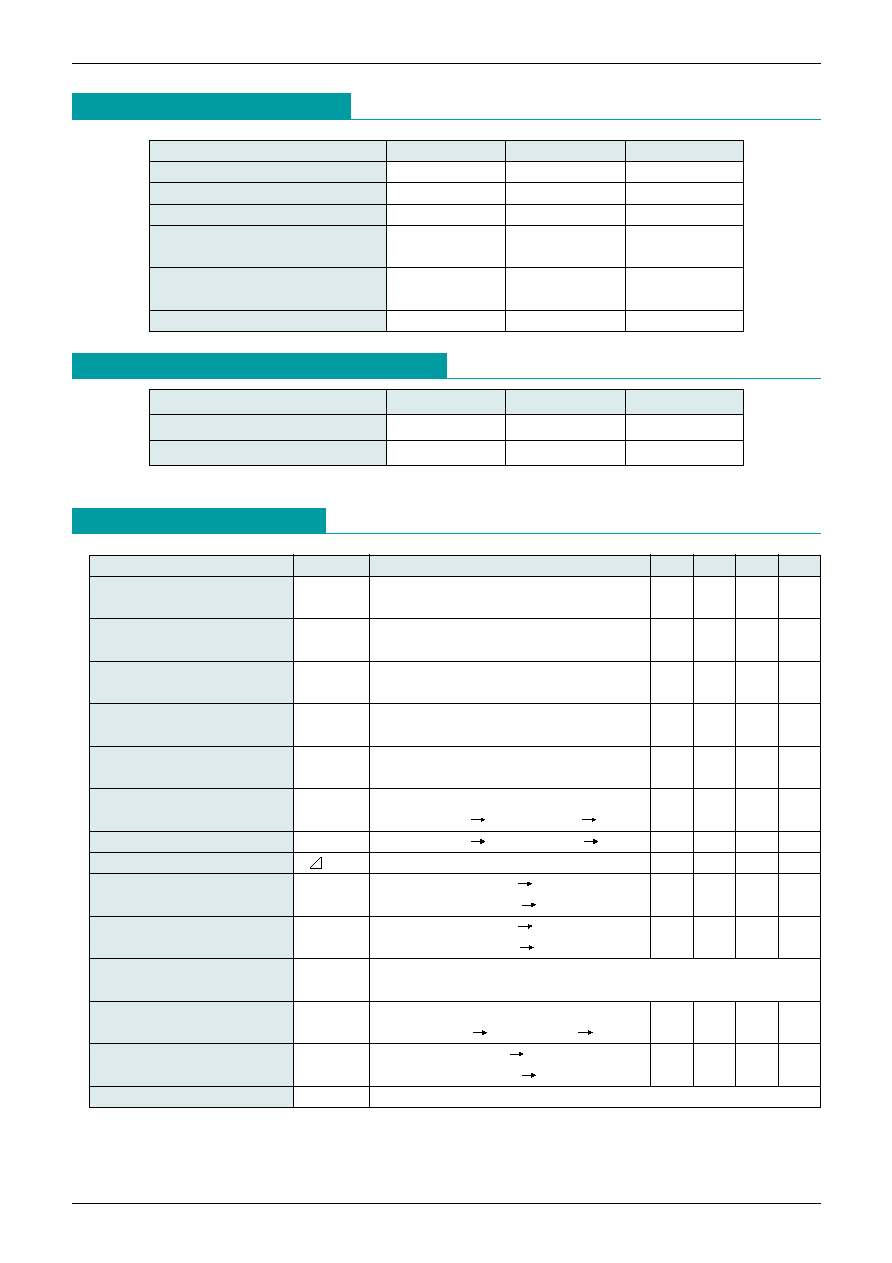
Pin Assignment
1
4
3
2
8
5
6
7
SOP-8B
1
GND
2
CS1
3
GD
4
CS2
5
OC2
6
TD
7
OC1
8
V
CC
*
1: Over-discharge detection voltage
*
2: Over-charge detection voltage
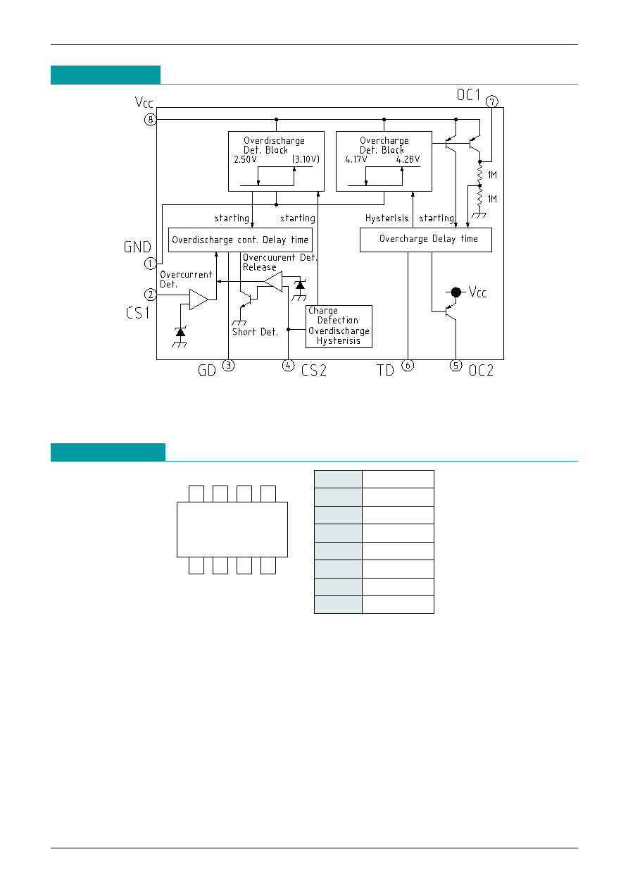
Block Diagram

MITSUMI
Lithium Ion Battery Protection (for 1-cell in series) MM1446
Pin Description
PIN No. PIN Name
Function
1
GND
2
CS1
3
GD
4
CS2
5
OC2
6
TD
7
OC1
8
V
CC
Negative power supply for this IC. Also act as detection voltage pin for the battery
connected between Vcc-GND.
Detection pin for voltage between CS1-GND.
When CS1 is connected with the Source of discharge FET, Detects overcurrent using an
external resistor and discharge current.
When CS1 is connected with CS2(4PIN), and connects with the Dorein of charge and
discharge FET, Detects overcurrent using an On state resistor of discharge control FET
and discharge current.
Dischage Current=CS1-GND Voltage / External Resistor
CS1-GND Voltage / On state resistance of discharge control FET
N-ch FET gate connection pin for discharge control. Switchesgate OFF when
overdischarge is detected, and for current protection. Swicthes gate ON when overcharge
is detected, and in normal state.
Detection pin for overcurrent mode release and start-up voltage.
Detected load release resets from overcurrent mode. When the battery is being charged
and the Voltage between CS2-GND during overdischarge mode falls bellow start-up
voltage, the bias current is drained to the interior circuit and operating status result.
Control pin for N-ch FET for charge control. Switches FET OFF by activating an external
transistor when overcharge is detected.
This operation continues until the voltage falls bellow overcharge release voltage.
Overcharge detection dead time setting pin.
T
ARAM
.
=. 10.0 C
TD
(sec)
C
TD
: TD pin external capacitance value (µF)
Overcharge detection output (input) pin. For overcharge detection, output goes high without
dead time set by TD pin. (Hysteresis does not go on until OC2 output goes high.)
Charging control FET is turned off by the OC2 pin when OC1 pin input is high.
Positive power supply for this IC. Also act as detection voltage pin for the battery connected
between Vcc-GND.
Overcharge Mode : Battery Voltage > Overcharge Det. Voltage
Nomal Mode : Overdischarge Det. Voltage < Battery Voltage < Overcharge Det. Voltage
Discharge Current < Overcurrent Det. Voltage / External Det. resistor
Overdischarge Mode : Overdischarge Det. Voltage > Battery Voltage
Overcurrent Mode : Discharge Current > Overcurrent Det. Voltage / External Det. Resistor
MITSUMI
Lithium Ion Battery Protection (for 1-cell in series) MM1446
Absolute Maximum Ratings
(Ta=25∞C)
Item
Symbol
Ratings
Unit
Storage temperature
T
STG
-40~+125
∞C
Operating temperature
T
OPR
-20~+70
∞C
Supply voltage
V
CC
max.
-0.3~+12
V
OC1 Terminal Voltage
V
OC1
max.
-0.3~V
CC
V
CS1 Terminal Voltage
V
CS1
max.
OC2 Terminal Voltage
V
OC2
max.
-0.6~V
CC
V
CS2 Terminal Voltage
V
CS2
max.
Allowable loss
P
D
170 (Alone)
mW
Recommended Operating Conditions
Item
Symbol
Ratings
Unit
Operating Temperature
T
OPR
-20~+70
∞C
Supply Voltage
V
OP
+0.9~+12
V
Item
Symbol
Measurement Conditions
Min. Typ. Max. Unit
Current Consumption 1
I
CC1
V
CC
=4.5V R
OC1
,
OC2
=
150
250
µA
(Overcharge Mode)
Current Consumption 2
I
CC2
V
CC
=3.5V
14
20
µA
(Nomal Mode)
Current Consumption 3
I
CC3
V
CC
=1.9V
0.2
0.5
µA
(Overdischarge Mode)
Current Consumption 4
I
CC4
V
CC
=1.9V (Ta=70∞C)
0.5
0.8
µA
(Overdischarge Mode)
Current Cosumption 5
I
CC5
V
CC
=4.5V, V
TD
=0V
(OC1 Output)
R
OC1
=
45
µA
Overcharge
V
ALM
Ta=0∞C ~ 50∞C
Detection Voltage
V
CC
=4.0V 4.5V, V
OC1
,
2
: L H
4.250 4.280 4.310
V
Overcharge Release Voltage
V
ALML
V
CC
=4.5V 4.0V, V
OC1
,
2
: H L
4.120 4.170 4.220
V
Overcharge Hysteresis Voltage
V
ALM
V
ALM
-V
ALML
80
110
140
mV
Overdischarge
V
OD
V
CC
=3.0V 2.0V
Detection Voltage
V
GD
: H L
2.45
2.50
2.55
V
Overdischarge
V
ODF
V
CC
=2.0V 4.0V
Resumption Voltage
V
GD
: L H
3.022 3.10 3.178
V
(
*
1)
(V
CC
>Overdischarge Release Voltage) or
(Charge and V
CC
>Overdischarge detection voltage.)
Start-up Voltage
V
ST
V
CC
=2.7V
V
CS2
: 0V -0.5V, V
GD
: L H
-0.4
-0.1
V
Overcurrent
V
CS1
V
CS1
: 0V -0.2V,
Detection Voltage
V
GD
: H L
34.5
39.5
43.5
mV
Overcurrent Protection Release
Load release (500MEG
min.)
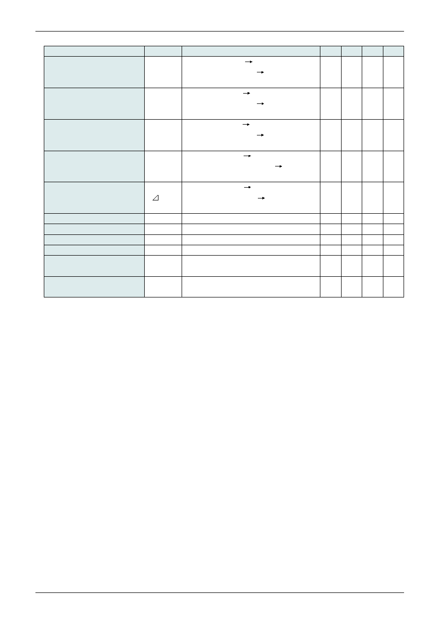
Electrical Characteristics
(Unless otherwise specifiedTa=25∞C, model name MM1446E)
MITSUMI
Lithium Ion Battery Protection (for 1-cell in series) MM1446
(
*
1) Refer to input waveforms.
(
*
2) Operation is unstable below the operating limit voltage.
Item
Symbol
Measurement Conditions
Min. Typ. Max. Unit
Overdischarge Detection
V
CC
=3.0V 2.0V (
*
1),
Delay Time
t
OD
V
GD
: H L
5.0
10.0
15.0
ms
CIRCUIT2, SW1 : a, SW2 : b, SW3 : b
Overcurrent Detection
V
CS1
=0V 0.2V (
*
1),
Delay Time 1
t
CS1
V
GD
: H L
5.0
10.0
15.0
ms
CIRCUIT2, SW1 : a, SW2 : b, SW3 : b
Overcurrent Detection
V
CS2
=0V 1.0V (
*
1) ,
Delay Time 2
t
CS2
V
GD
: H L
100
µs
CIRCUIT2, SW1 : b, SW2 : a, SW3 : b
Overcharge Detection
V
CC
=4.0V 4.5V (
*
1) ,
Delay Time 1
t
ALM1
C
TD
=0.1µF, V
OC2
: L H
0.5
1.0
1.5
s
CIRCUIT2, SW1 : a, SW2 : b, SW3 : b
Overcharge Detection
V
CC
=4.0V 4.5V (
*
1) ,
Delay Time 2
t
ALM2
V
OC1
: H L
100
µs
CIRCUIT2, SW1 : a, SW2 : b, SW3 : b
Operating Limit Voltage (
*
2)
V
OP
V
CC
when V
GDL2
>0.4V
1.2
V
GD Terminal Output Voltage H
V
GDH
V
CC
-0.3 V
CC
-0.1
V
GD Terminal Output Voltage L1
V
GDL1
V
CS2
>1.0V
0.1
0.3
V
GD Terminal Output Voltage L2
V
GDL2
V
CC
=1.5V
0.2
0.4
V
OC1 Terminal Output Current
I
OC1
V
CC
=4.5V, V
OC1
=1.6V
CIRCUIT1, SW1 : b, SW2 : a
-30
µA
OC2 Terminal Output Current
I
OC2
V
CC
=4.5V, V
OC1
=0V
CIRCUIT1, SW1 : a, SW2 : b
-500
µA

MITSUMI
Lithium Ion Battery Protection (for 1-cell in series) MM1446
Measuring Circuit
Note :
Measuring Circuit 1
Measuring Circuit 2
0.2V
V
CS1
V
GD
t
CS
0V
3.0V
V
CC
V
OD
1V/100
µ
s
2.0V
V
GD
t
OD
1V/100
µ
s
4.5V
V
CC
V
ALM
V
GD
t
ALM
4.0V
MITSUMI
Lithium Ion Battery Protection (for 1-cell in series) MM1446
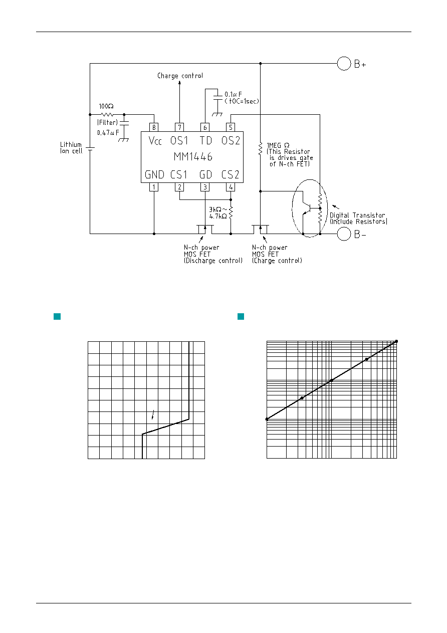
Application Circuits
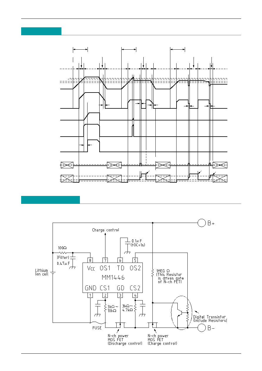
Timing Chart
Normal
mode
Normal
mode
Normal
mode
Normal
mode
Charge
Undecided
Undecided
Undecided
Undecided
Undecided
Load release
Undecided
Charge
Charge
Normal mode
Over current protection mode
Over current
protection mode
Charging
prohibited
mode
Discharging
prohibited
mode
Discharging
prohibited
mode
Discharging
prohibited
mode
Over current
protection mode
V
ALM
T
OO
T
ALM2
T
OO
T
CS
T
CS
T
CS
V
CS
V
Sr
(V
CS2
)
OV
V
CC
GD
TD
OC1
OC2
CS1
CS2
OV
OV
OV
OV
OV
OV
V
ALML
V
DDF
V
DO
Load release
Load release
Normal mode
Over discharging
mode
Undecided
Undecided
(1) Example using shunt resistance to detect overcurrent.
MITSUMI
Lithium Ion Battery Protection (for 1-cell in series) MM1446
50
Supply voltage (V
CC
) (V)
40
30
20
I
CC
10
0
1.0
2.0
3.0
5.0
4.0
Supply current (I
CC
) (
µ
A)
10
1
0.1
0.01
0.01
0.1
1.0
External capacitance (C
TD
) (
µ
F)
Overcharge detection time (sec.)
Supply current vs supply voltage
Overcharge detection time
(deat time)
Note: The above specifications are representative, and are not guaranteed values.
Note: Applicable circuits shown are typical examples provided for reference purposes. Mitsumi cannot
assume responsibility for any problems arising out of the use of these circuits or for any infringement of
third party patent and other right due to same.
(2) Example using discharge FET on resistance to detect overcurrent.