 | –≠–ª–µ–∫—Ç—Ä–æ–Ω–Ω—ã–π –∫–æ–º–ø–æ–Ω–µ–Ω—Ç: MM1519XQ | –°–∫–∞—á–∞—Ç—å:  PDF PDF  ZIP ZIP |

MITSUMI
Component input video swich with I
2
C BUS MM1519XQ
Component input video swich with I
2
C BUS
Monolithic IC MM1519XQ
Outline
This IC is a color difference input video switch with I
2
C BUS control, developed for high resolution TV.
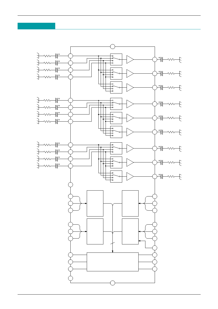
With 3 output lines, it supports, among others, P-IN-P, monitor output and decoder output.
Features
1. Serial control by I
2
C BUS.
2. 4 color difference input lines, 3 output lines (3 input lines support D pin standards)
3. Built-in 6dB amp
4. Slave address can be changed: 94H or 96H
5. High band video SW supports D4 input (Y: 50MHz/P
B
, P
R
: 25MHz)
6 .out 2 and out 3 have power save function.
7. 1 output line that can be controlled optionally by I
2
C BUS built-in.
Package
QFP-64B
Applications
1. HDTV
2. SDTV
3. Other video equipment
MITSUMI
Component input video swich with I
2
C BUS MM1519XQ
Block Diagram
75
75
75
75
1
µ
1
µ
1
µ
1
µ
Tun-Y
V1-Y
V2-Y
V3-Y
6dB
6dB
6dB
Y OUT1
Y OUT2
Y OUT3
10
µ
10k
10
µ
10k
10k
10
µ
75
1
µ
75
75
1
µ
1
µ
75
1
µ
P
B
OUT3
P
B
OUT2
V3-P
B
V2-P
B
6dB
6dB
10k
10
µ
10
µ
10k
10
µ
10k
P
B
OUT1
Tun-P
B
V1-P
B
6dB
1
µ
1
µ
75
75
75
1
µ
75
1
µ
P
R
OUT3
6dB
10
µ
10k
P
R
OUT2
P
R
OUT1
V3-P
R
V2-P
R
V1-P
R
Tun-P
R
6dB
6dB
10
µ
10k
10
µ
10k
V
CC
(9V)
DV
CC
(5V)
V1-L2
V2-L2
V3-L2
V3-L1
V2-L1
V1-L1
V2-L3
V3-SW
V2-SW
V1-SW
V3-L3
V1-L3
Monitor SW
L1 OUT
L2 OUT
L3 OUT
SCL
SDA
ADDRESS
DGND
l
2
C Logic
GND
(19)
Detection information
Line2
distinction
(Interless
infomation)
Line1
infomation)
(Scanning line
distinction
SW line
distinction
infomation)
distinction
Line3
(Aspect

MITSUMI
Component input video swich with I
2
C BUS MM1519XQ
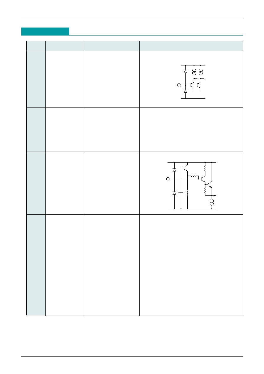
Pin Assignment
(TOP VIEW)
1
L1
L2
L3
V
CC
Y
GND
Pb
GND
Pr
SW
L1
L2
L3
V
CC
Y
GND
Pb
GND
Pr
AV
CC
Y
OUT
1
GND
Pb
OUT
1
GND
Pr
OUT
1
V
CC
Y
OUT
2
GND
Pb
OUT
2
GND
Pr
OUT
2
V
CC
Y
OUT
3
GND
Pb
OUT
3
GND
Pr
OUT
3
GND
3
7
6
2
4
5
8
51
48
46
50
49
47
44
9
43
10
42
11
41
12
40
13
39
14
38
15
37
16
36
17
35
18
34
19
33
32
31
30
29
28
27
26
25
24
23
22
21
20
MonSW
L1
OUT
L2
OUT
L3
OUT
DV
CC
SCL
SDA
ADDRESS
DGND
L3
L2
L1
SW
V
CC
Y
GND
Pb
GND
Pr
V
CC
Y
GND
Pb
GND
Pr
SW
52
53
54
55
56
57
58
59
60
61
62
63
64
45
Video2
Video3
OUT1
Tuner
D
OUT
Video1
OUT2
OUT3
MITSUMI
Component input video swich with I
2
C BUS MM1519XQ
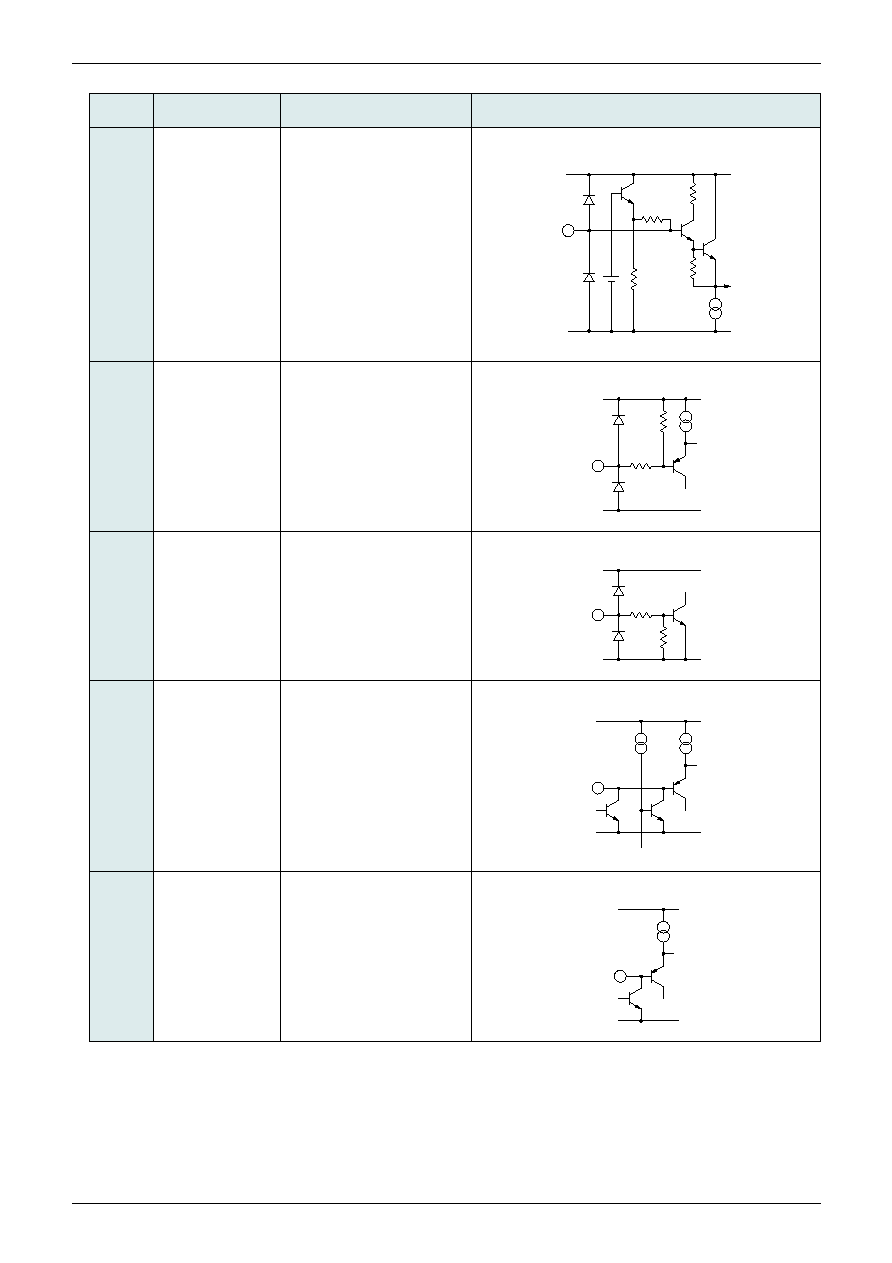
Pin Description
Pin No.
Pin name
Function
Internal equivalent circuit diagram
DV
CC
(5V)
1
Video1-L1
Line input of D-terminal
2
Video1-L2
3
Video1-L3
11
Video2-L1
12
Video2-L2
13
Video2-L3
21
Video3-L1
22
Video3-L2
23
Video3-L3
4
V
CC
Analog V
CC
14
AV
CC
39
45
51
52
58
6.1V
V
CC
(9V)
150k
5
Video2-Y
Y input
15
Video3-Y
53
Tuner-Y
59
Video1-Y
6
GND
GND
8
DGND
16
18
24
33
35
37
41
43
47
49
54
56
60
62
MITSUMI
Component input video swich with I
2
C BUS MM1519XQ
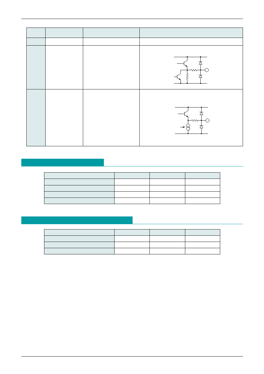
Pin No.
Pin name
Function
Internal equivalent circuit diagram
5.8V
V
CC
(9V)
150k
DV
CC
(5V)
10k
7
Video2-Pb
Pb,Pr input
9
Video2-Pr
17
Video3-Pb
19
Video3-Pr
55
Tuner-Pb
57
Tuner-Pr
61
Video1-Pb
63
Video1-Pr
10
Video2-SW
SW-Line of D terminal
20
Video3-SW
32
MonSW
64
Video1-SW
DV
CC
(5V)
70k
30k
DV
CC
(5V)
ACK
25
ADDRESS
Slave Address select pin
26
SDA
Data input of I
2
C BUS
DV
CC
(5V)
27
SCL
CLK input of I
2
C BUS
MITSUMI
Component input video swich with I
2
C BUS MM1519XQ
Pin No.
Pin name
Function
Internal equivalent circuit diagram
DV
CC
(5V)
10k
10k
28
DV
CC
Digital V
CC
29
L3
OUT
Line output for Monitor
30
L2
OUT
31
L1
OUT
AV
CC
(9V)
50
ON/OFF
34
Pr
OUT
3
Video output
36
Pb
OUT
3
38
Y
OUT
3
40
Pr
OUT
2
42
Pb
OUT
2
44
Y
OUT
2
46
Pr
OUT
1
48
Pb
OUT
1
50
Y
OUT
1
Absolute Maximum Ratings
(Ta=25∞C)
Item
Symbol
Ratings
Units
Storage temparature
T
STG
-40~+125
∞C
Operating temparature
T
OPR
-20~+75
∞C
Supply voltage
V
CC
max.
13
V
Power dissipation
Pd
1300
mW
Recommended Operating Conditions
Item
Symbol
Ratings
Units
Operating temparature
T
OPR
-20~+75
∞C
Operating voltage
V
OP1
+8.0~+10.0
V
Operating voltage
V
OP2
+4.5~+5.5
V
MITSUMI
Component input video swich with I
2
C BUS MM1519XQ
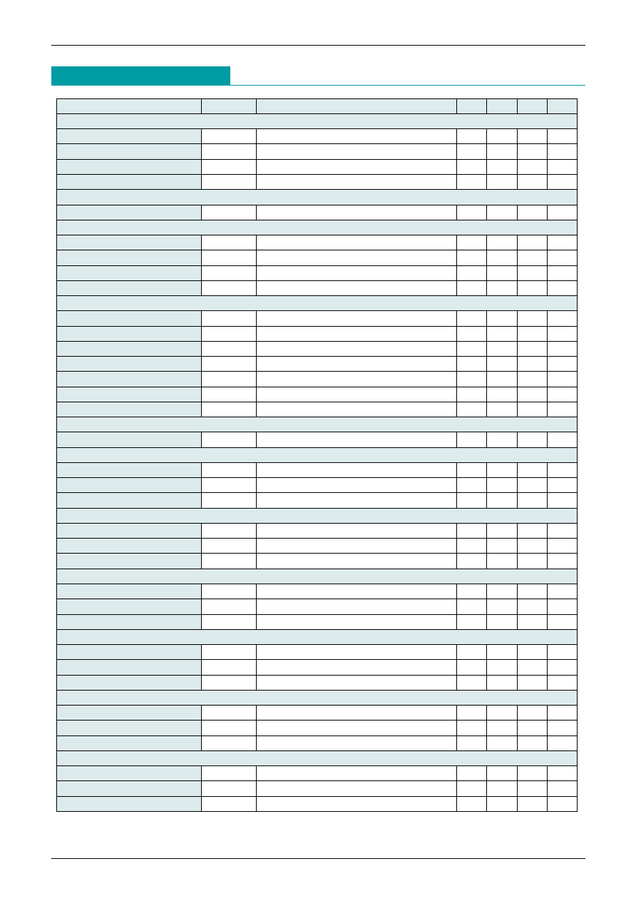
Electrical Characteristics
(Except where noted therwise, Ta=25∞C, V
CC
=AV
CC
=9V, DV
CC
=5V)
Item
Symbol
Measurement conditions
Min. Typ. Max. Units
[V
CC
& AV
CC
] (Analog V
CC
[9V] )
Current consumption
I
CC
0
No signal
67
87
mA
Current of power-save 1
I
CC
1
Out2 is turn-off, Out1&3 are active
55
72
mA
Current of power-save 2
I
CC
2
Out3 is turn-off, Out1&2 are active
55
72
mA
Current of power-save 3
I
CC
3
Out2&3 are turn-off, Out1 is active
43
60
mA
[DV
CC
] (Digital V
CC
[5V] )
Current consumption
I
CC
4
No signal
8
10
mA
[Terminal voltage]
Y input terminal
V
YIN
53, 59, 5, 15 pin
4.8
5.2
5.6
V
Pb,Pr input terminal
V
PIN
55, 57, 61, 63, 7, 9, 17, 19 pin
4.5
4.9
5.3
V
Y output terminal
V
YOUT
50, 44, 38 pin
4.0
4.4
4.8
V
Pb, Pr output terminal
V
POUT
48, 46, 42, 40, 36, 34 pin
3.9
4.3
4.7
V
[D connecter conditions]
Line1~3 detect level L
Vdet
L
1, 2, 3, 11, 12, 13, 21, 22, 23 pin
0.6
1.0
1.4
V
Line1~3 detect level H
Vdet
H
1, 2, 3, 11, 12, 13, 21, 22, 23 pin
2.4
2.9
3.4
V
Switch detect level L
Vdet
L
64, 10, 20, 32 pin
1.8
V
Switch detect level H
Vdet
H
64, 10, 20, 32 pin
3.5
V
Line output level L
V
LL
0.4
V
Line output level M
V
LM
1.4
2.4
V
Line output level H
V
LH
3.4
V
[Address terminal]
Address threshold level
Vth
ADR
1.5
2.0
2.5
V
[Input terminal impedance]
Y input
R
YIN
100
150
200
k
Pb input
R
PBIN
100
150
200
k
Pr input
R
PBIN
100
150
200
k
[Y
OUT
1]
Voltage gain
G
Y1
SIN wave: 1V
P-P
, 100kHz
5.5
6.0
6.5
dB
Frequency characteristic
f
Y1
SIN wave: 1V
P-P
50MHz/100kHz
-3
dB
Input dynamic range
D
Y1
SIN wave: 100kHz THD=1.0%
2.5
3.0
V
P-P
[Y
OUT
2]
Voltage gain
G
Y2
SIN wave: 1V
P-P
, 100kHz
5.5
6.0
6.5
dB
Frequency characteristic
f
Y1
SIN wave: 1V
P-P
50MHz/100kHz
-3
dB
Input dynamic range
D
Y2
SIN wave: 100kHz THD=1.0%
2.5
3.0
V
P-P
[Y
OUT
3]
Voltage gain
G
Y3
SIN wave: 1V
P-P
, 100kHz
5.5
6.0
6.5
dB
Frequency characteristic
f
Y1
SIN wave: 1V
P-P
50MHz/100kHz
-3
dB
Input dynamic range
D
Y3
SIN wave: 100kHz THD=1.0%
2.5
3.0
V
P-P
[Pb
OUT
1]
Voltage gain
G
PB1
SIN wave: 1V
P-P
, 100kHz
5.5
6.0
6.5
dB
Frequency characteristic
f
Y1
SIN wave: 1V
P-P
25MHz/100kHz
-3
dB
Input dynamic range
D
PB1
SIN wave: 100kHz THD=1.0%
2.5
3.0
V
P-P
[Pb
OUT
2]
Voltage gain
G
PB2
SIN wave: 1V
P-P
, 100kHz
5.5
6.0
6.5
dB
Frequency characteristic
f
Y1
SIN wave: 1V
P-P
25MHz/100kHz
-3
dB
Input dynamic range
D
PB2
SIN wave: 100kHz THD=1.0%
2.5
3.0
V
P-P
MITSUMI
Component input video swich with I
2
C BUS MM1519XQ
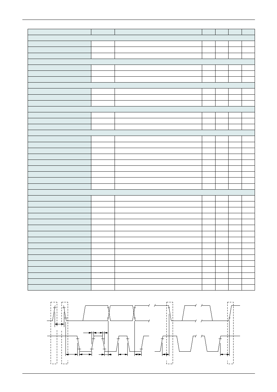
Item
Symbol
Measurement conditions
Min. Typ. Max. Units
[Pb
OUT
3]
Voltage gain
G
PB3
SIN wave: 1V
P-P
, 100kHz
5.5
6.0
6.5
dB
Frequency characteristic
f
Y1
SIN wave: 1V
P-P
25MHz/100kHz
-3
dB
Input dynamic range
D
PB3
SIN wave: 100kHz THD=1.0%
2.5
3.0
V
P-P
[Pr
OUT
1]
Voltage gain
G
PR1
SIN wave: 1V
P-P
, 100kHz
5.5
6.0
6.5
dB
Frequency characteristic
f
Y1
SIN wave: 1V
P-P
25MHz/100kHz
-3
dB
Input dynamic range
D
PR1
SIN wave: 100kHz THD=1.0%
2.5
3.0
V
P-P
[Pr
OUT
2]
Voltage gain
G
PR2
SIN wave: 1V
P-P
, 100kHz
5.5
6.0
6.5
dB
Frequency characteristic
f
Y1
SIN wave: 1V
P-P
25MHz/100kHz
-3
dB
Input dynamic range
D
PR2
SIN wave: 100kHz THD=1.0%
2.5
3.0
V
P-P
[Pr
OUT
3]
Voltage gain
G
PR3
SIN wave: 1V
P-P
, 100kHz
5.5
6.0
6.5
dB
Frequency characteristic
f
Y1
SIN wave: 1V
P-P
25MHz/100kHz
-3
dB
Input dynamic range
D
PR3
SIN wave: 100kHz THD=1.0%
2.5
3.0
V
P-P
[Crosstalk]
Y
OUT
1
CT
Y1L
SIN wave: 1V
P-P
, 5MHz
-65
-55
dB
Y
OUT
2
CT
Y2L
SIN wave: 1V
P-P
, 5MHz
-65
-55
dB
Y
OUT
3
CT
Y3L
SIN wave: 1V
P-P
, 5MHz
-65
-55
dB
Pb
OUT
1
CT
PB1
SIN wave: 1V
P-P
, 5MHz
-65
-55
dB
Pb
OUT
2
CT
PB2
SIN wave: 1V
P-P
, 5MHz
-65
-55
dB
Pb
OUT
3
CT
PB3
SIN wave: 1V
P-P
, 5MHz
-65
-55
dB
Pr
OUT
1
CT
PR1
SIN wave: 1V
P-P
, 5MHz
-65
-55
dB
Pr
OUT
2
CT
PR2
SIN wave: 1V
P-P
, 5MHz
-65
-55
dB
Pr
OUT
3
CT
PR3
SIN wave: 1V
P-P
, 5MHz
-65
-55
dB
[I
2
C condition]
Input voltage L
V
IL
0
1.5
V
Input voltage H
V
IH
3.0
5.0
V
SDA low level output voltage
V
OL
SDA sink 3mA
0
0.4
V
High level input current
I
IH
SDA, SCL=4.5V
-10
10
µA
Low level input current
I
IL
SDA, SCL=0.4V
-10
10
µA
Clock frequency
f
SCL
100
kHz
Data transfer wait time
t
BUF
4.7
µs
SCL start hold time
t
HD; STA
4.0
µs
SCL low level hold time
t
LOW
4.7
µs
SCL high level hold time
t
HIGH
4.0
µs
Start condition setup time
t
SU; STA
4.7
µs
SDA data hold time
t
HD; DAT
200
ns
SDA data setup time
t
SU; DAT
250
ns
SDA, SCL rise time
t
R
1000
ns
SDA, SCL fall time
t
F
300
ns
Stop condition setup time
t
SU; STO
4.0
µs
SDA
P
S
Sr
P
SCL
t
BUF
t
HD:STA
t
R
t
F
t
HD:DAT
t
HIGH
t
SU:DAT
t
SU:STA
t
SU:STO
t
LOW
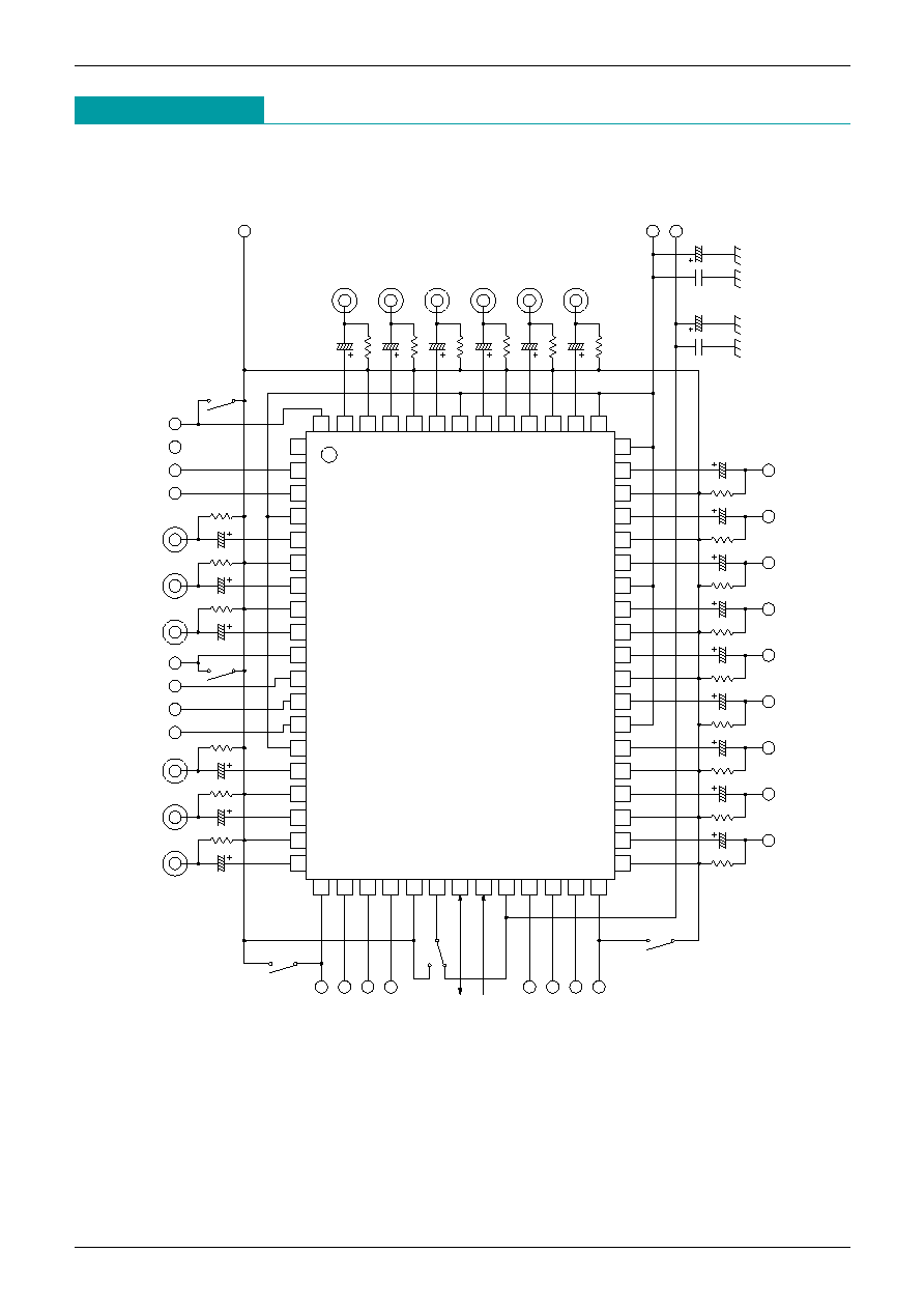
Note.1 I
2
C condition
MITSUMI
Component input video swich with I
2
C BUS MM1519XQ
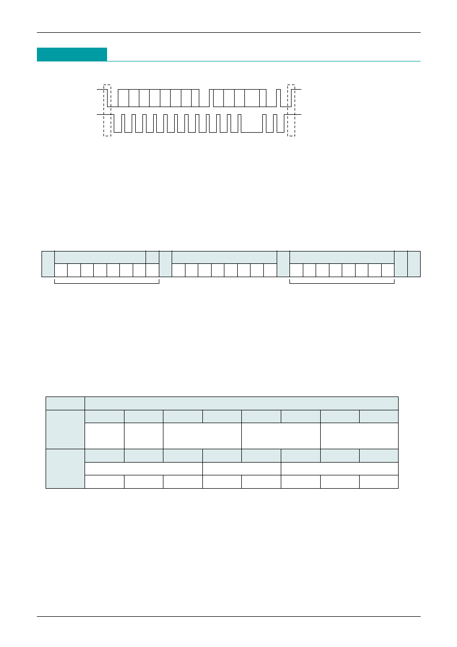
Measuring Circuit
19
18
17
10
8
9
7
16
15
14
13
12
3
6
5
11
1
2
4
20 21 22
25
24
23
28
27
26
29 30 31 32
49
51
62
63
64
57
60
61
58
59
55
56
52
53
54
50
48
47
46
45
44
43
42
33
34
35
36
37
38
39
40
41
S1
Video1-SW
Video1-L1
Video1-L2
Video1-L3
Video2-Y
Video2-Pb
Video2-Pr
Video2-SW
Video2-L1
Video2-L2
Video2-L3
Video3-Y
Video3-Pb
Video3-Pr
75
1
µ
1
µ
75
1
µ
75
1
µ
75
1
µ
75
1
µ
75
S2
S3
S4
S5
10k
10
µ
10
µ
10k
10k
10
µ
10k
10
µ
10k
10
µ
10
µ
10k
10k
10
µ
10k
10
µ
10
µ
10k
100
µ
0.1
µ
0.1
µ
100
µ
75
1
µ
1
µ
75
75
1
µ
75
1
µ
75
1
µ
75
1
µ
GND
Video1-Pb
Video1-Pr
Video1-Y
Tuner-Pb
Tuner-Pr
Tuner-Y
Vcc(5V)
Vcc(9V)
Y
OUT
3
Pr
OUT
3
Pb
OUT
3
Pb
OUT
2
Pr
OUT
2
Y
OUT
2
Pr
OUT
1
Y
OUT
1
Pb
OUT
1
Mon SW
L1
OUT
L2
OUT
L3
OUT
Video3-L3
Video3-L2
Video3-L1
Video3-SW
SCL
SDA
I
2
C BUS is inter bus system controled by 2 lines (SDA,SCL).
Data are transmitted and received in the units of byte and Acknowledge.
It is transmitted by MSB first from the Start conditions.
[Control registers]
Control registers are data sent from the master for determining the switch conditions.
The data format is set as shown in the following figure.
Out of the Address byte, first 7bit are assigned to the slave address,while the residual 1bit is assigned to the
R/W bit.
Set the R/W bit to 0 when data are used control registers.
As MM1519 slave address, either 94H or 96H can be selected according to the ADR terminal conditions.
When ADR terminal is L,94H is selected.
The following figure indicates the control contents of control registers and switches.
Each bit of control registers is reset to 0,when power-on.
MM1519 consists of one address byte and two control data bytes (3bytes in total).
All data over the limited length (4th and subsequent bytes) are fully neglected.
For details of the control contents of switches, refer to the another table.
MITSUMI
Component input video swich with I
2
C BUS MM1519XQ
I
2
C BUS
SDA
SCL
S
P
1 2 3
1 2 3
4 5 6 7 8 A
8 A
S:Start Condition
P:Stop Condition
A:Acknowledge
Address byte
Data byte
S
Slave address
R/W
1
0
0
1
0
1 0/1 0
A
DATA1
b07 b06 b05 b04 b03 b02 b01 b00
A
DATA2
b27 b26 b25 b24 b23 b22 b21 b20
A
P
No.
DATA condition
DATA1
b07
b06
b05
b04
b03
b02
b01
b00
[00H]
Power Power
Out1 select
Out2 select
Out3 select
save 2
save 3
DATA2
b17
b16
b15
b14
b13
b12
b11
b10
[00H]
Line1 output
Line2 output
Line3 output
1080
720
480
60p
60i
16 : 9
Letter Box
4 : 3

MITSUMI
Component input video swich with I
2
C BUS MM1519XQ
Switch Control Table
Out1 select
Out2 select
Out3 select
Line1 output
Line2 output
Line3 output
b05
b04
Y
OUT
1
Pb
OUT
1
Pr
OUT
1
0
0
Tuner-Y
Tuner-Pb
Tuner-Pr
0
1
Video1-Y
Video1-Pb
Video1-Pr
1
0
Video2-Y
Video2-Pb
Video2-Pr
1
1
Video3-Y
Video3-Pb
Video3-Pr
b14
b13
L2
OUT
0
0
0V
0
1
0V
1
0
5V
1
1
0V
b07
b03
b02
Y
OUT
2
Pb
OUT
2
Pr
OUT
2
0
0
Tuner-Y
Tuner-Pb
Tuner-Pr
0
0
1
Video1-Y
Video1-Pb
Video1-Pr
1
0
Video2-Y
Video2-Pb
Video2-Pr
1
1
Video3-Y
Video3-Pb
Video3-Pr
1
OFF
OFF
OFF
b17
b16
b15
L1
OUT
0
0
0
0V
0
0
1
0V
0
1
0
2.2V
0
1
1
0V
1
0
0
5V
1
0
1
0V
1
1
0
0V
1
1
1
0V
b12
b11
b10
L1
OUT
0
0
0
0V
0
0
1
0V
0
1
0
2.2V
0
1
1
0V
1
0
0
5V
1
0
1
0V
1
1
0
0V
1
1
1
0V
b06
b01
b00
Y
OUT
3
Pb
OUT
3
Pr
OUT
3
0
0
Tuner-Y
Tuner-Pb
Tuner-Pr
0
0
1
Video1-Y
Video1-Pb
Video1-Pr
1
0
Video2-Y
Video2-Pb
Video2-Pr
1
1
Video3-Y
Video3-Pb
Video3-Pr
1
OFF
OFF
OFF
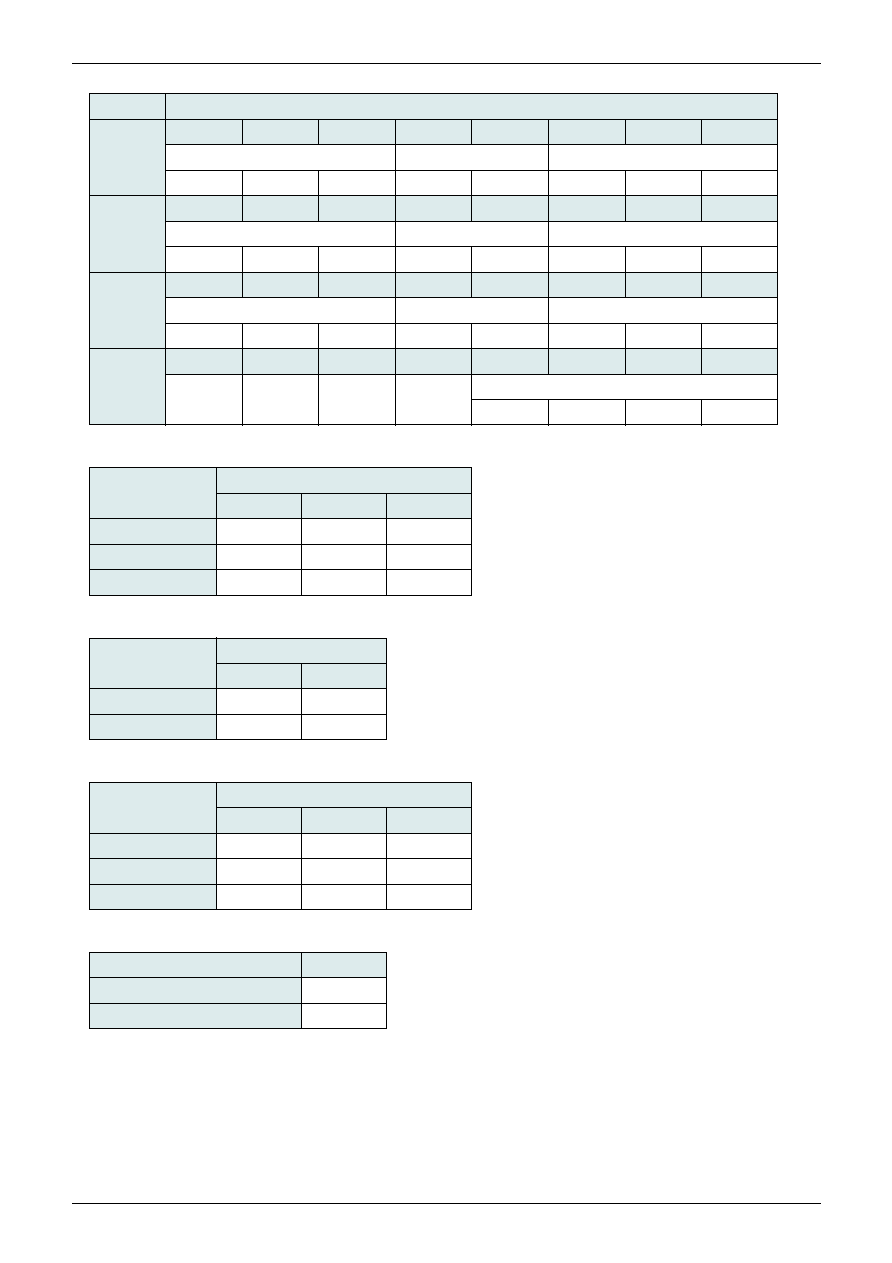
[Status registers]
Status registers are data to inform the master of the device status.
The data format is set as shown in the following figure.
Out of the Address byte, first 7bit are assigned to the slave address, while the residual 1bit is assigned to the
R/W bit. Set the R/W bit to 1 when data are used status registers.
As MM1519 slave address, either 95H or 97H can be selected according to the ADR terminal conditions.
When ADR terminal is L,95H is selected.
Set the confirmation acknowledgement after the end of status register to non-ACK.
The following figure shows the correspondence of the output data of status registers.
Address byte
S
Slave address
R/W
1
0
0
1
0
1 0/1 1
A
DATA4
b27 b26 b25 b24 b23 b22 b21 b20
A
DATA5
b37 b36 b35 b34 b33 b32 b31 b30
A
Status byte
DATA5
b47 b46 b45 b44 b43 b42 b41 b40
A
DATA6
b57 b56 b55 b54 b53 b52 b51 b50
A
P
MITSUMI
Component input video swich with I
2
C BUS MM1519XQ
No.
DATA condition
b27
b26
b25
b24
b23
b22
b21
b20
DATA3
Line1 (Out1)
Line2 (Out1)
Line3 (Out1)
1080
720
480
60p
60i
16:9
Letter Box
4 : 3
b37
b36
b35
b34
b33
b32
b31
b30
DATA4
Line1 (Out2)
Line2 (Out2)
Line3 (Out2)
1080
720
480
60p
60i
16:9
Letter Box
4 : 3
b47
b46
b45
b44
b43
b42
b41
b40
DATA5
Line1 (Out3)
Line2 (Out3)
Line3 (Out3)
1080
720
480
60p
60i
16:9
Letter Box
4 : 3
b57
b56
b55
b54
b53
b52
b51
b50
DATA6
Switch line detect
Video1
Video2
Video3
Mon SW
L1 voltage
Scanning line
1080
720
480
DC <
= 0.8V
0
0
1
1.4V <
= DC <
= 2.4V
0
1
0
3.5V <
= DC <
= 5.0V
1
0
0
L3 voltage
Aspect
16 : 9
Letter box
4 : 3
DC <
= 0.8V
0
0
1
1.4V <
= DC <
= 2.4V
0
1
0
3.5V <
= DC <
= 5.0V
1
0
0
L2 voltage
I/P
60p
60i
DC <
= 2.4V
0
1
3.5V <
= DC <
= 5.0V
1
0
SW voltage
Switch line
DC <
= 1.8V (connected)
0
3.2V <
= DC (unconnected)
1
MITSUMI
Component input video swich with I
2
C BUS MM1519XQ
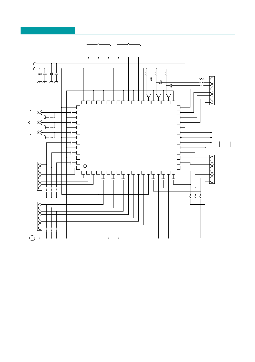
Application Circuit
19
18
17
10
8
9
7
16
15
14
13
12
3
6
5
1
11
2
4
20
21
22
25
24
23
28
27
26
29
30
31
32
49
51
62
63
64
57
60
61
58
59
55
56
52
53
54
50
48 47 46 45 44 43 42
33
34
35
36
37
38
39
40
41
0.1
µ
DVcc
Vcc
SCL(0V~5V)
SDA(0V~5V)
0.1
µ
0.1
µ
0.1
µ
0.1
µ
0.1
µ
0.1
µ
470
µ
470
µ
470
µ
100
µ
0.1
µ
100
µ
0.1
µ
GND
Video2
D-input
D-input
Video1
75 75 75
75
75
75
Y
PB
PR
TUNER
Y
OUT
1
MAIN
PB
OUT
1
PR
OUT
1
PB
OUT
2
Y
OUT
2
SUB
PR
OUT
2
75
75
75
75
75
75
75
D-input
Video3
0.1
µ
0.1
µ
0.1
µ
0.1
µ
0.1
µ
Mon OUT
ADR 0V=94h
5V=96h


