 | –≠–ª–µ–∫—Ç—Ä–æ–Ω–Ω—ã–π –∫–æ–º–ø–æ–Ω–µ–Ω—Ç: PST600CM | –°–∫–∞—á–∞—Ç—å:  PDF PDF  ZIP ZIP |

MITSUMI
System Reset PST600
System Reset
Monolithic IC PST600
Outline
This IC operates in a variety of CPU systems and other logic systems by detecting power supply voltage, so
that the system can be reset accurately when power is turned on or when power is momentarily cut. PST572
and others perform the same function as does this series, but this IC is a low reset type system resetting IC
which follows load current so that circuit current flow increases for ON, and has low current consumption for
both ON and OFF.
Features
1. Follows load current so that circuit current flow increases for ON, and has low current consumption for
both ON and OFF.
No load : I
CCL
=7µA typ.; I
CCH
=5µA typ.
2. Low operating limit voltage
0.65V typ.
3. Hysteresis voltage provided in detection voltage 50mV typ.
4. The following 10 ranks of detection voltages are available.
PST600
C : 4.5V typ.
H : 3.1V typ.
D : 4.2V typ.
I : 2.9V typ.
E : 3.9V typ.
J : 2.7V typ.
F : 3.6V typ.
K : 2.5V typ.
G : 3.3V typ.
L : 2.3V typ.
Package
MMP-3A (PST600
M)
TO-92A (PST600
)
*
contains detection voltage rank.
Applications
1. Microcomputers, CPU, MPU reset circuits
2. Logic circuit reset circuits
3. Battery voltage check circuits
4. Back-up power supply switching circuits
5. Level detection circuits
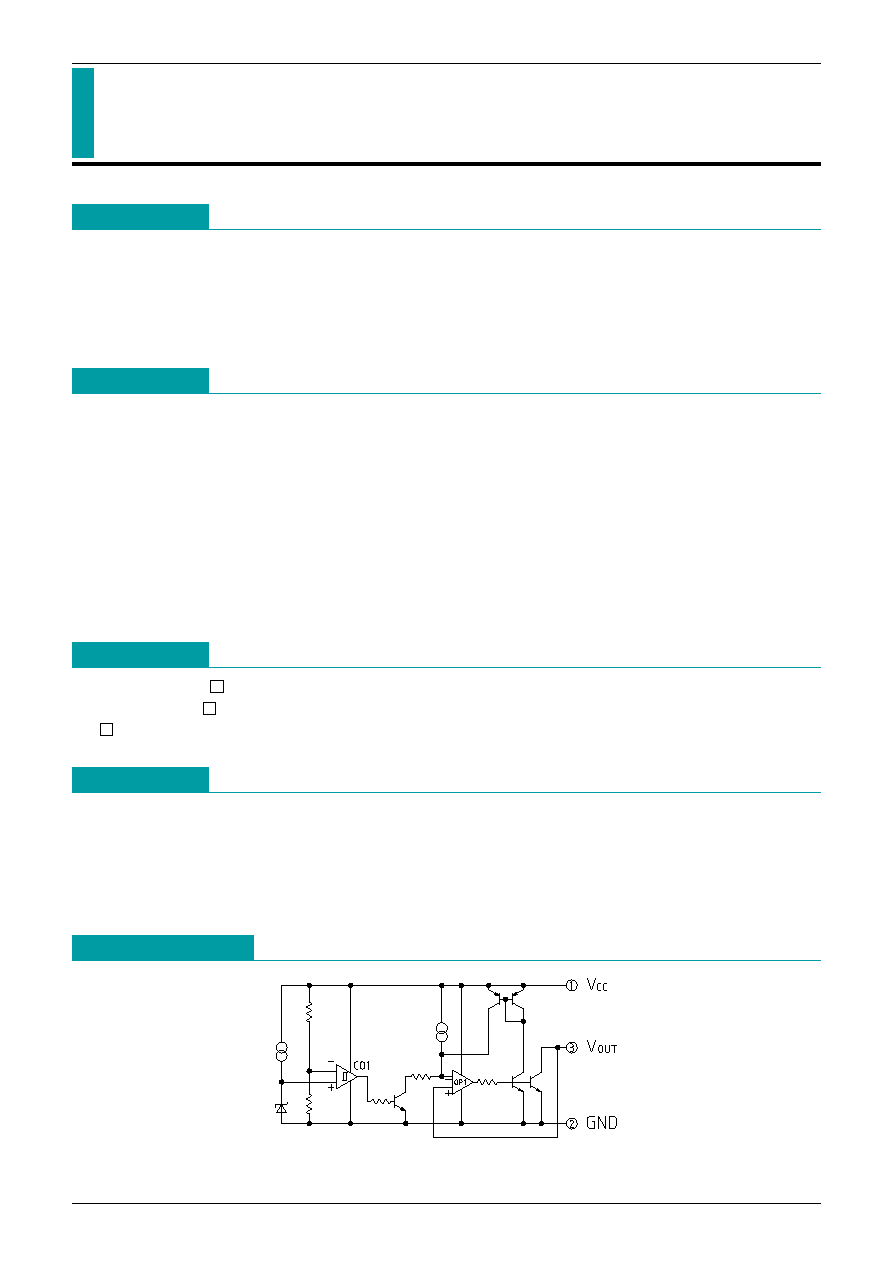
Equivalent Circuit

MITSUMI
System Reset PST600
Absolute Maximum Ratings
(Ta=25
∞
C)
Electrical Characteristics
(Ta=25
∞
C) (unless otherwise indicated resistance unit is
)
*
1 t
PLH
: V
CC
= (Vs typ. -0.4V) (Vs typ.+0.4V), t
PLH
: V
CC
= (Vs typ.+0.4V) (Vs typ.-0.4V)
*
2 V
CC
=Vs min. -0.15V
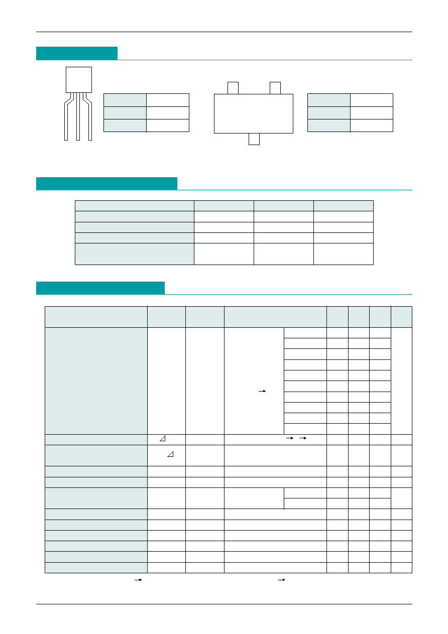
Pin Assignment
1
2
3
TO-92A
3
1
2
MMP-3A
(TOP VIEW)
1
V
CC
2
GND
3
V
OUT
1
V
CC
2
GND
3
V
OUT
Item
Symbol
Ratings
Units
Storage temperature
T
STG
-40~+125
∞
C
Operating temperature
T
OPR
-20~+75
∞
C
Power supply voltage
V
CC
max.
-0.3~10
V
Allowable loss
Pd
200 (MMP-3A)
mW
300 (TO-92A)
Item
Symbol
Measurement
Measurement conditions
Min. Typ. Max. Units
circuit
PST600C
4.3
4.5
4.7
PST600D
4.0
4.2
4.4
PST600E
3.7
3.9
4.1
R
L
=470
PST600F
3.4
3.6
3.8
Detection voltage
Vs
1
V
OL
<
= 0.4V
PST600G
3.1
3.3
3.5
V
V
CC
=H
L
PST600H
2.9
3.1
3.3
PST600I
2.75
2.90
3.05
PST600J
2.55
2.70
2.85
PST600K
2.35
2.50
2.65
PST600L
2.15
2.30
2.45
Hysteresis voltage
Vs
1
R
L
=470, V
CC
=L
H
L
30
50
100
mV
Detection voltage
temperature coefficient
Vs/ T
1
R
L
=470, Ta=-20
∞
C~+75
∞
C
±0.01
%/
∞
C
Low level output voltage
V
OL
1
V
CC
=Vs min. -0.05V, R
L
=470
0.3
0.4
V
Output leak current
I
OH
1
V
CC
=10V
±0.1
µA
Circuit current for ON
I
CCL
1
V
CC
=Vs min.
I
OL
=0mA
7
14
µA
-0.05V
I
OL
=8mA
50
130
Circuit current for OFF
I
CCH
1
V
CC
=Vs typ./0.85V, R
L
=
5
10
µA
H transmission delay time
t
PLH
2
R
L
=4.7k, C
L
=100pF
*
1
20
40
80
µs
L transmission delay time
t
PHL
2
R
L
=4.7k, C
L
=100pF
*
1
10
20
40
µs
Operating limit voltage
VopL
1
R
L
=4.7k, V
O
L <
= 0.4V
0.65
0.85
V
Output current 1 for ON
I
OL
1
1
V
CC
=Vs min. -0.05V, R
L
=0
8
mA
Output current 2 for ON
I
OL
2
1
Ta=-20
∞
C~+75
∞
C, R
L
=0
*
2
6
mA

MITSUMI
System Reset PST600
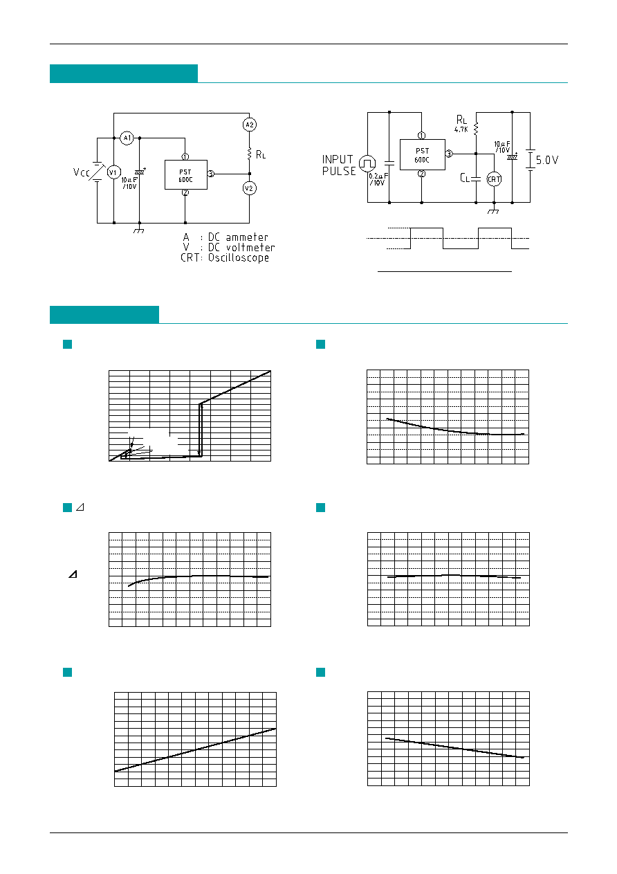
Measurement Circuit
[1]
[2]
Characteristics
(PST600C is used as the representative model for characteristics examples.)
-40
-20
0
20
40
60
80
4.2
4.3
4.4
4.5
4.6
4.7
V
S
(V)
Ta(
∞
C)
V
S
(mV)
Ta (
∞
C)
-40
-20
0
20
40
60
80
20
30
40
50
60
70
80
V
S
vs. Ta
V
S
vs. Ta
V
O
L
(mV)
Ta (
∞
C)
-40
-20
0
20
40
60
80
200
250
300
350
400
450
Ta=-25
∞
C
Ta=25
∞
C
Ta=75
∞
C
8
7
6
5
4
3
2
1
0
0
1
2
3
4
5
6
7
8
Vout
(V)
V
CC
(V)
V
CC
vs. V
OUT
V
O
L vs. Ta
V
S
0V
4.9
4.1
*
The input model is an example of PST600C (MMP-3P).
I
CC
H
(
µ
A)
Ta(
∞
C)
-40
-20
0
20
40
60
80
3
4
5
6
7
8
I
CC
L
(
µ
A)
I
O
L (mA)
0
2
4
6
8
10
12
0
20
40
60
80
100
I
CC
L vs. I
O
L
I
CC
H vs. Ta

MITSUMI
System Reset PST600
I
CC
L
(
µ
A)
Ta (
∞
C)
-40
-20
0
20
40
60
80
4
5
6
7
8
9
I
CC
L (I
O
L=0mA) vs. Ta
V
O
L
(mV)
I
O
L (mA)
0
2
4
6
8
10
12
0
100
200
300
400
500
I
O
L
(mA)
Ta (
∞
C)
-40
-20
0
20
40
60
80
10
20
30
40
50
60
I
O
L vs. Ta
V
O
L vs. I
O
L
Application Circuits
1. Normal hard reset
Delay Time (tPLH)
C
L
: µF
Vs
CPU
: CPU, MPU reset threshold voltage
R
L
: k
Voltage : V
Note : When V
CC
line impedance is high, connect a
capacitor between IC Pins 1 and 2.
2. Manual Reset
Note : Prevent Manual SW chattering by using R
L
, C
L
and Rm. Rm setting conditions are as follows :
Rm <
= 1/20 R
L
Note : When V
CC
line impedance is high,connect a
capacitor between IC Pins 1 and 2.
V
CC
∑=∑C
L
R
L
[
ln ------------------------
]
+0.040 (ms)
V
CC
- (VS
CPU
+0.2)

MITSUMI
System Reset PST600
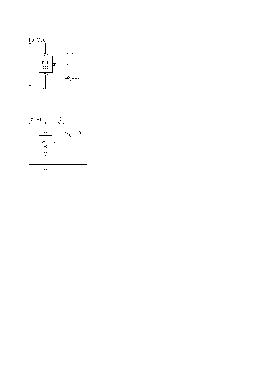
3. Battery Checker (LED ON for High voltage)
Note : When V
CC
line impedance is high, connect a
capacitor between IC Pins 1 and 2.
4. Battery Checker (LED ON for Low voltage)
Note : When V
CC
line impedance is high, connect a
capacitor between IC Pins 1 and 2.


