MITSUMI
System Reset PST90XX
System Reset
Monolithic IC PST90XX Series
Outline
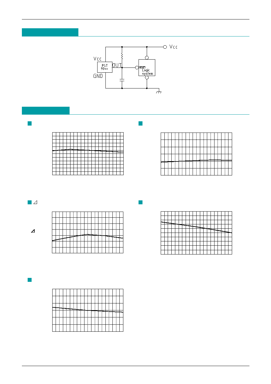
The function of this low voltage detection type IC is to accurately reset systems after detecting the supply
voltage at the time of switching power on and instantaneous power off in various CPU and other logic
systems. This IC, with its super low consumption current and high precision voltage detection capacity, is
most suited as a voltage check circuit for a number of products which use batteries.
Features
1. High precision voltage detection
V
S
±2.5% max.
2. Super low current consumption
I
CCH
=1.5µA typ. I
CCL
=1µA typ.
3. Low operating threshold voltage
0.7V max.
4. Hysteresis voltage is provided as a detect voltage
Vs 5% typ.
5. The detect voltage can be selected at your discretion at 0.1 V step within the range of 0.8 to 1.8V by the
following stipulation method.
PST90XX
Detected voltage value
(Example : for 0.8V ∑∑∑∑∑∑ PST9008)
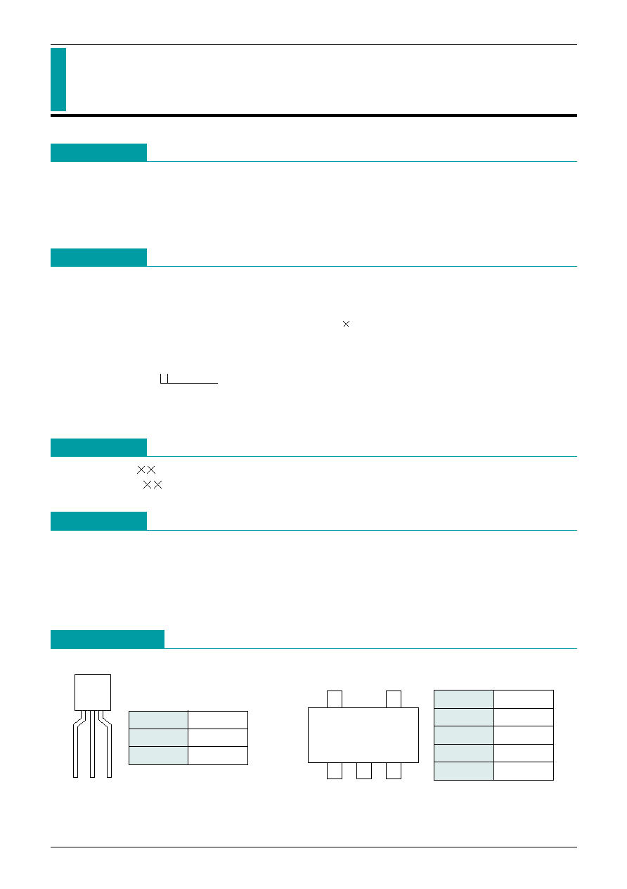
Package
TO-92A (PST90 )
SOT-25A (PST90 N)
Applications
1. Reset circuits for microcomputers, CPU and MPU.
2. Reset circuit for logic circuitry.
3. Battery voltage check circuit.
4. Circuit for changing over to backup battery.
5. Level detecting circuit.
Pin Assignment
1
2
3
TO-92A
5
4
1
2
3
SOT-25A
(TOP VIEW)
1
V
OUT
2
V
CC
3
GND
Note : The pin 2 of SOT-25 package is a SUB terminal. Connect it to GND.
1
NC
2
SUB
3
GND
4
V
OUT
5
V
CC
MITSUMI
System Reset PST90XX
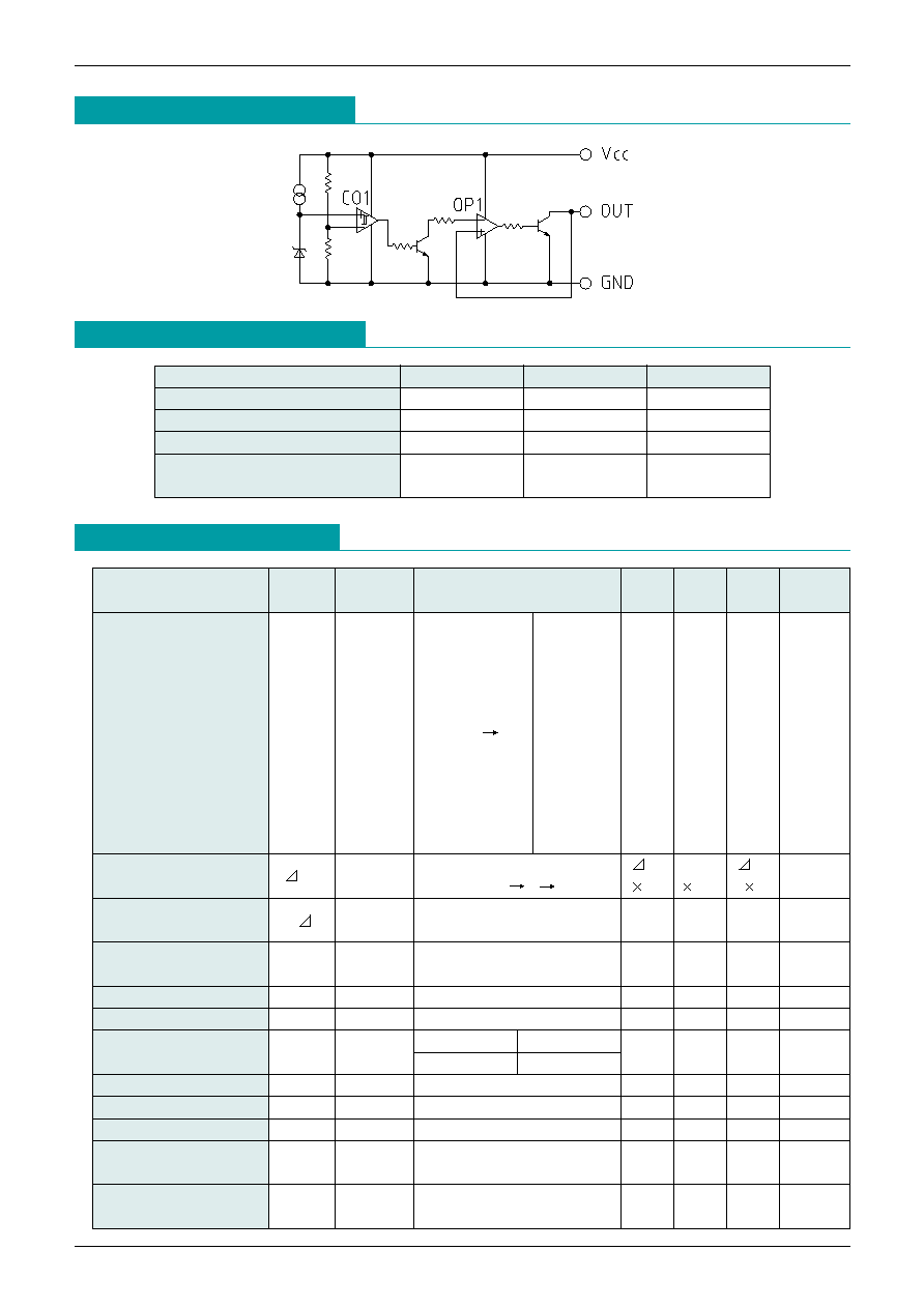
Absolute Maximum Ratings
(Ta=25
∞
C)
Electrical Characteristics
(Ta=25
∞
C) (The unit of resistance is
unless otherwise indicated.)
Equivalent Circuit Diagram
Item
Symbol
Ratings
Units
Storage temperature
T
STG
-40~+125
∞
C
Operating temperature
T
OPR
-20~+75
∞
C
Supply Voltage
V
CC
max.
-0.3~10
V
Allowable loss
Pd
150 (SOT-25A)
mW
300 (TO-92A)
Item
Symbol
Measurement
Measurement conditions
Min.
Typ.
Max.
Unit
Circuit
PST9008
0.8
PST9009
0.9
PST9010
1.0
PST9011
1.1
R
L
=4.7k
PST9012
-2.5%
1.2
+2.5%
Detection Voltage
V
S
1
V
CC
=H L
PST9013
typ.
1.3
typ.
V
V
OL
<
= 0.4V
PST9014
1.4
PST9015
1.5
PST9016
1.6
PST9017
1.7
PST9018
1.8
Hysteresis Voltage
V
S
1
R
L
=4.7k
V
S
V
S
typ.
V
S
mV
V
CC
=L H L
0.5
0.05
2
Detection Voltage
V
S
/ T
1
R
L
=4.7k
±0.01
%/
∞
C
Temperature Coefficient
Ta=-20
∞
C~+75
∞
C
Low Level
V
O
L
1
V
CC
=Vs min. -0.02V
0.2
0.4
V
Output Voltage
R
L
=4.7k
Output Leakage Current
I
O
H
1
V
CC
=10V
0.1
µA
Circuit Current at On Time
I
CCL
1
V
CC
=Vs min. -0.02V I
OL
=0mA
1.0
2.0
µA
Circuit Current at
I
CCH
1
Vs=0.8~1.2
V
CC
=1.5V, R
L
=
1.0
2.0
µA
OFF Time
Vs=1.3~1.8
V
CC
=3.0V, R
L
=
"H" Transmission Delay Time
tpLH
2
C
L
=100pF, R
L
=4.7k
10
20
50
µs
"L" Transmission Delay Time
tpHL
2
C
L
=100pF, R
L
=4.7k
20
50
80
µs
Operating Threshold Voltage
VopL
1
R
L
=4.7k, V
OL
<
= 0.4V
0.65
0.70
V
Output Current at
I
O
L1
1
R
L
=0
0.3
mA
On Time 1
V
CC
=Vs min. -0.02V
Output Current at
I
O
L2
1
V
CC
=Vs min. -0.02V
0.2
mA
On Time 2
R
L
=0, Ta=-20
∞
C~+75
∞
C