MITSUMI
49MHz Band Transmitting-Receiving Module Conforming to FCC
WMF-T12, R10
FEATURES
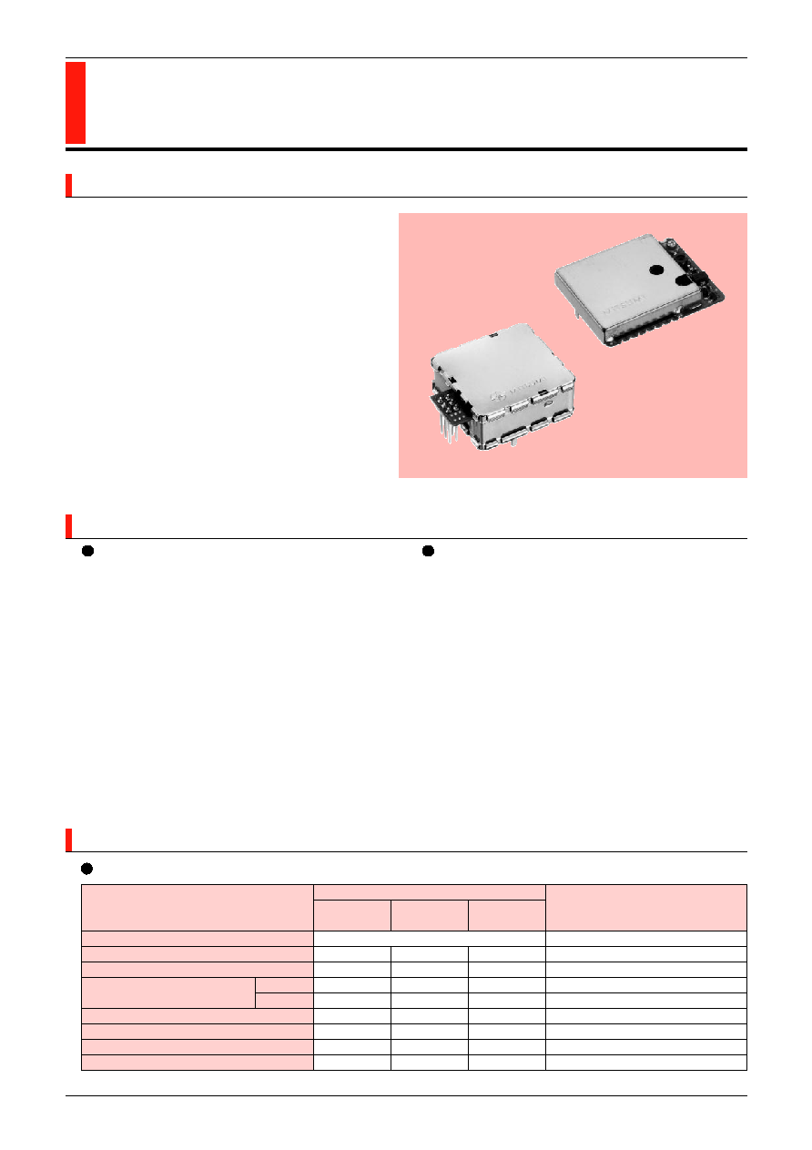
WMF series small electric wave type transceiver
modules have been developed as a wireless
controller for PC. Since these modules can be
fleely and directly soldered on PC boards, a non-
directional wireless control system can easily be
realized.
Telecommunication component
SPECIFICATIONS
FEATURES
Transmitting Module (WMF-T12)
1. Thin and lightweight.
2. Supply voltage 4.5V~5.5V.
3. Can be directly soldered on PC boards.
4. Low current consumption 20mA (typ.).
5. Can be paired with receiving module (WMF-R10).
6. 30ms (max.) rise time from power on.
7. 7 channels can be used, at 10kHz intervals.
Receiving Module (WMF-R10)
1. Thin and lightweight.
2. 5V supply voltage.
3. Can be directly soldered on PC boards.
4. TTL level data output.
5. Can be paired with transmitting module (WMF-
T12).
Specifications
Item
Remarks
min.
typ.
max.
Transmitting Frequency
49.83MHz~49.89MHz (10kHz step)
Transmitting Output
80dBµV/m
at 3m
Deviation Width
1.0kHz
1.5kHz
2.0kHz
FSK
HIGH
4.0V
Data Input Level
LOW
0.4V
Supply Voltage
4.5V
5.0V
5.5V
Current Consumption
Transmission Rate
4800bps
Rock-up Time
25mS 30mS
Transmitting Module (WMF-T12)
WMF-T12
WMF-R10

MITSUMI
49MHz Band Transmitting-Receiving Module Conforming to FCC
Specifications
Item
Remarks
min.
typ.
max.
Receiving Frequency
49.83MHz~49.89MHz (10kHz step)
Sensitivity
12dBµ
BER = 0.01 (4800dps PN9)
Spurious Response
35dB
HIGH
4.0V
Data Output Level
LOW
0.4V
Current Consumption
10mA 15mA
Demodulated Transmission Rate
4800bps
Receiving Module (WMF-R10)
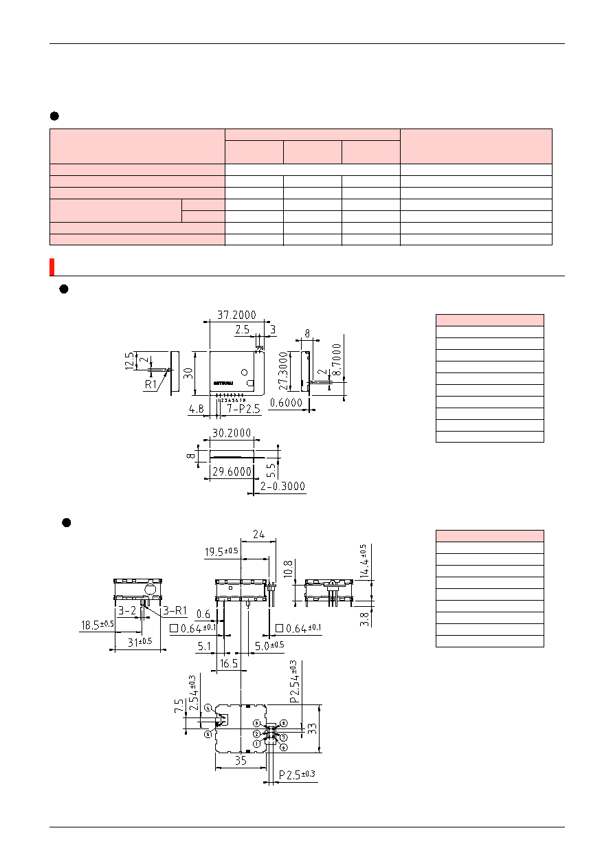
DIMENSIONS
Transmitting Module/WMF-T12
TERMINALS
1. PLL CE
2. PLL CL
3. PLL DI
4. LOCK
5. DATA
6. +B
7. STROBE
8. GND
9. GND
10. ANT
Receiving Module/WMF-R10
TERMINALS
1. +B
2. DATA OUT
3. GROUND
4. ANT
5. ANT GROUND
6. PLL CE
7. PLL DA
8. PLL CK
CASE GROUND
Unit : mm
*
For the technical details of the products in this page, please refer to Sales promotion Dept., TOCHIGI MITUMI Co., Ltd. Phone: 0283 (23) 3332.

