MOTOROLA
SEMICONDUCTOR
TECHNICAL DATA
Motorola TVS/Zener Device Data
7-1
3 Watt DC Power Data Sheet
Devices listed in bold, italic are Motorola preferred devices.
3 Watt Plastic Surface Mount
Silicon Zener Diodes
This complete new line of 3 Watt Zener Diodes offers the following advantages.
Specification Features:
∑
A Complete Voltage Range -- 3.3 to 200 Volts
∑
Flat Handling Surface for Accurate Placement
∑
Package Design for Top Side or Bottom Circuit Board Mounting
∑
Available in Tape and Reel
Mechanical Characteristics:
CASE: Void-free, transfer-molded plastic
MAXIMUM CASE TEMPERATURE FOR SOLDERING PURPOSES: 260
∞
C for 10 seconds
FINISH: All external surfaces are corrosion resistant with readily solderable leads
POLARITY: Cathode indicated by molded polarity notch. When operated in zener mode,
cathode will be positive with respect to anode.
MOUNTING POSITION: Any
WEIGHT: Modified L-Bend providing more contact area to bond pad
WAFER FAB LOCATION: Phoenix, Arizona
ASSEMBLY/TEST LOCATION: Seremban, Malaysia
MAXIMUM RATINGS
Rating
Symbol
Value
Unit
DC Power Dissipation @ TL = 75
∞
C, Measured at Zero Lead Length
Derate above 75
∞
C
PD
3
40
Watts
mW/
∞
C
DC Power Dissipation @ TA = 25
∞
C*
Derate above 25
∞
C
PD
830
6.6
mW
mW/
∞
C
Operating and Storage Junction Temperature Range
TJ, Tstg
≠ 65 to +150
∞
C
*FR4 Board, within 1
to device, using Motorola minimum recommended footprint, as shown in case 403A outline dimensions spec.
ELECTRICAL CHARACTERISTICS
(TL = 30
∞
C unless otherwise noted.) (VF = 1.5 Volts Max @ IF = 200 mAdc for all types.)
Device*
Nominal
Zener Voltage
VZ @ IZT
Volts
(Note 1)
Test
Current
IZT
mA
Max Zener Impedance (Note 2)
Max Reverse
Leakage Current
Maximum DC
Zener
Current
IZM
mAdc
Device
Marking
Device*
VZ @ IZT
Volts
(Note 1)
Current
IZT
mA
ZZT @ IZT
Ohms
ZZK
Ohms
IZK
mA
@
IR
µ
A
VR
Volts
@
Current
IZM
mAdc
Device
Marking
1SMB5913BT3
3.3
113.6
10
500
1
100
1
454
913B
1SMB5914BT3
3.6
104.2
9
500
1
75
1
416
914B
1SMB5915BT3
3.9
96.1
7.5
500
1
25
1
384
915B
1SMB5916BT3
4.3
87.2
6
500
1
5
1
348
916B
1SMB5917BT3
4.7
79.8
5
500
1
5
1.5
319
917B
1SMB5918BT3
5.1
73.5
4
350
1
5
2
294
918B
1SMB5919BT3
5.6
66.9
2
250
1
5
3
267
919B
1SMB5920BT3
6.2
60.5
2
200
1
5
4
241
920B
1SMB5921BT3
6.8
55.1
2.5
200
1
5
5.2
220
921B
1SMB5922BT3
7.5
50
3
400
0.5
5
6.8
200
922B
1SMB5923BT3
8.2
45.7
3.5
400
0.5
5
6.5
182
923B
1SMB5924BT3
9.1
41.2
4
500
0.5
5
7
164
924B
1SMB5925BT3
10
37.5
4.5
500
0.25
5
8
150
925B
1SMB5926BT3
11
34.1
5.5
550
0.25
1
8.4
136
926B
1SMB5927BT3
12
31.2
6.5
550
0.25
1
9.1
125
927B
1SMB5928BT3
13
28.8
7
550
0.25
1
9.9
115
928B
(continued)
*TOLERANCE AND VOLTAGE DESIGNATION
Tolerance designation -- The type numbers listed indicate a tolerance of
±
5%.
CASE 403A
PLASTIC
1SMB5913BT3
through
1SMB5956BT3
PLASTIC SURFACE MOUNT
ZENER DIODES
3 WATTS
3.3≠200 VOLTS

1SMB5913BT3 Series
Motorola TVS/Zener Device Data
7-2
3 Watt DC Power Data Sheet
Devices listed in bold, italic are Motorola preferred devices.
ELECTRICAL CHARACTERISTICS -- continued
(TL = 30
∞
C unless otherwise noted.) (VF = 1.5 Volts Max @ IF = 200 mAdc for all
types.)
Device*
Nominal
Zener Voltage
VZ @ IZT
Volts
(Note 1)
Test
Current
IZT
mA
Max Zener Impedance (Note 2)
Max Reverse
Leakage Current
Maximum DC
Zener
Current
IZM
mAdc
Device
Marking
Device*
VZ @ IZT
Volts
(Note 1)
Current
IZT
mA
ZZT @ IZT
Ohms
ZZK
Ohms
IZK
mA
@
IR
µ
A
VR
Volts
@
Current
IZM
mAdc
Device
Marking
1SMB5929BT3
15
25
9
600
0.25
1
11.4
100
929B
1SMB5930BT3
16
23.4
10
600
0.25
1
12.2
93
930B
1SMB5931BT3
18
20.8
12
650
0.25
1
13.7
83
931B
1SMB5932BT3
20
18.7
14
650
0.25
1
15.2
75
932B
1SMB5933BT3
22
17
17.5
650
0.25
1
16.7
68
933B
1SMB5934BT3
24
15.6
19
700
0.25
1
18.2
62
934B
1SMB5935BT3
27
13.9
23
700
0.25
1
20.6
55
935B
1SMB5936BT3
30
12.5
26
750
0.25
1
22.8
50
936B
1SMB5937BT3
33
11.4
33
800
0.25
1
25.1
45
937B
1SMB5938BT3
36
10.4
38
850
0.25
1
27.4
41
938B
1SMB5939BT3
39
9.6
45
900
0.25
1
29.7
38
939B
1SMB5940BT3
43
8.7
53
950
0.25
1
32.7
34
940B
1SMB5941BT3
47
8
67
1000
0.25
1
35.8
31
941B
1SMB5942BT3
51
7.3
70
1100
0.25
1
38.8
29
942B
1SMB5943BT3
56
6.7
86
1300
0.25
1
42.6
26
943B
1SMB5944BT3
62
6
100
1500
0.25
1
47.1
24
944B
1SMB5945BT3
68
5.5
120
1700
0.25
1
51.7
22
945B
1SMB5946BT3
75
5
140
2000
0.25
1
56
20
946B
1SMB5947BT3
82
4.6
160
2500
0.25
1
62.2
18
947B
1SMB5948BT3
91
4.1
200
3000
0.25
1
69.2
16
948B
1SMB5949BT3
100
3.7
250
3100
0.25
1
76
15
949B
1SMB5950BT3
110
3.4
300
4000
0.25
1
83.6
13
950B
1SMB5951BT3
120
3.1
380
4500
0.25
1
91.2
12
951B
1SMB5952BT3
130
2.9
450
5000
0.25
1
98.8
11
952B
1SMB5953BT3
150
2.5
600
6000
0.25
1
114
10
953B
1SMB5954BT3
160
2.3
700
6500
0.25
1
121.6
9
954B
1SMB5955BT3
180
2.1
900
7000
0.25
1
136.8
8
955B
1SMB5956BT3
200
1.9
1200
8000
0.25
1
152
7
956B
*TOLERANCE AND VOLTAGE DESIGNATION
Tolerance designation -- The type numbers listed indicate a tolerance of
±
5%.

1SMB5913BT3 Series
Motorola TVS/Zener Device Data
7-3
3 Watt DC Power Data Sheet
Devices listed in bold, italic are Motorola preferred devices.
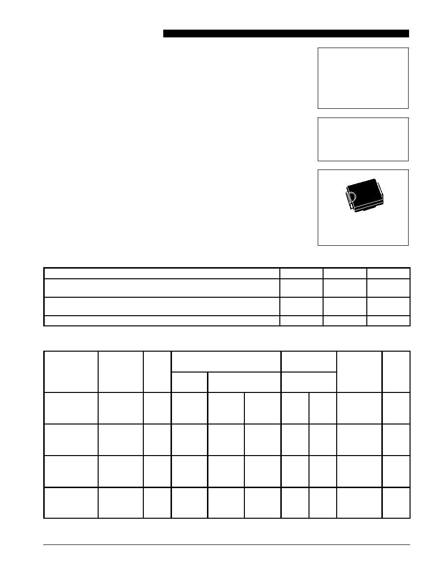
Figure 1. Steady State Power Derating
0
25
50
75
100
125
150
6
5
4
3
2
0
T, TEMPERATURE (
∞
C)
P
, MAXIMUM POWER DISSIP
A
TION (W
A
TTS)
D
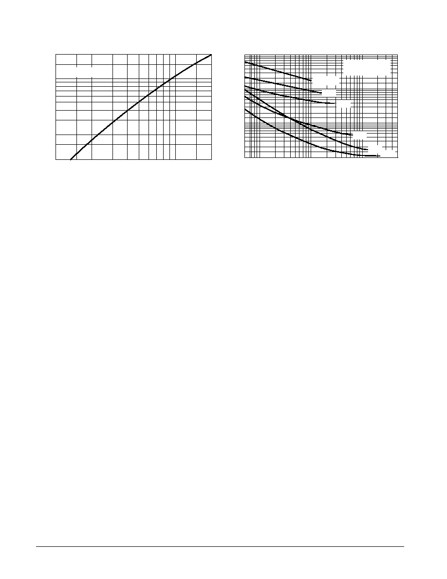
10
20
30
50
100
200
300
500
1K
0.1
0.2 0.3 0.5
1
2
3
5
10
20 30 50
100
PW, PULSE WIDTH (ms)
P
, PEAK SURGE POWER (W
A
TTS)
PK
Figure 2. Maximum Surge Power
RECTANGULAR
NONREPETITIVE
WAVEFORM
TJ = 25
∞
C PRIOR
TO INITIAL PULSE
Figure 3. Zener Voltage -- To 12 Volts
2
4
6
8
10
12
10
8
6
4
2
0
≠2
≠4
VZ, ZENER VOLTAGE (VOLTS)
,
TEMPERA
TURE COEFFICIENT
(mV/ C)
∞
VZ
Figure 4. VZ = 3.3 thru 10 Volts
0
1
2
3
4
5
6
7
8
9
10
100
50
30
20
10
1
0.5
0.3
0.2
0.1
VZ, ZENER VOLTAGE (VOLTS)
I , ZENER CURRENT
(mA)
Z
2
5
3
Figure 5. VZ = 12 thru 82 Volts
0
10
20
30
40
50
60
70
80
90
100
VZ, ZENER VOLTAGE (VOLTS)
I , ZENER CURRENT
(mA)
Z
100
50
30
20
10
1
0.5
0.3
0.2
0.1
2
5
3
Figure 6. Effect of Zener Voltage
VZ, ZENER VOLTAGE (VOLTS)
5
7
10
20
30
50
70
100
200
100
70
50
30
20
10
7
5
3
2
Z , DYNAMIC IMPEDANCE (OHMS)
Z
1
VZ @ IZT
10mA
IZ(dc) = 1mA
20mA
iZ(rms) = 0.1 IZ(dc)
TL
TA
1SMB5913BT3 Series
Motorola TVS/Zener Device Data
7-4
3 Watt DC Power Data Sheet
Devices listed in bold, italic are Motorola preferred devices.
Figure 7. Zener Voltage -- 14 To 200 Volts
Figure 8. Effect of Zener Current
200
100
70
50
30
20
10
10
20
30
50
70
100
200
VZ, ZENER VOLTAGE (VOLTS)
,
TEMPERA
TURE COEFFICIENT
(mV/ C)
∞
VZ
IZ, ZENER TEST CURRENT (mA)
1k
500
200
100
50
20
10
5
2
1
0.5
1
2
5
10
20
50
100
200
500
Z , DYNAMIC IMPEDANCE (OHMS)
Z
VZ @ IZT
TJ = 25
∞
C
iZ(rms) = 0.1 IZ(dc)
VZ =150V
91V
62V
22V
12V
6.8V
NOTE 1. ZENER VOLTAGE (VZ) MEASUREMENT
Nominal zener voltage is measured with the device junction in thermal equilibrium with ambi-
ent temperature at 25
∞
C.
NOTE 2. ZENER IMPEDANCE (ZZ) DERIVATION
ZZT and ZZK are measured by dividing the ac voltage drop across the device by the ac current
applied. The specified limits are for IZ(ac) = 0.1 IZ(dc) with the ac frequency = 60 Hz.