 | –≠–ª–µ–∫—Ç—Ä–æ–Ω–Ω—ã–π –∫–æ–º–ø–æ–Ω–µ–Ω—Ç: AN1812 | –°–∫–∞—á–∞—Ç—å:  PDF PDF  ZIP ZIP |

This document describes how to design a platform with a common footprint for the MPC750,
MPC755, MPC7400, and MPC7410; that is, it is intended to help design a single board
compatible with all of these devices. Although this document contains relevant information, it
is not intended to be a complete migration guide for moving from G3- to G4-class systems.
As a general note, refer to the appropriate hardware specifications and user's manual for the
specific device under consideration.
For this document, the following system definition is assumed for the MPC750, MPC755,
MPC7400 and MPC7410:
∑
64-bit data bus mode
∑
No data retry
∑
Bus operates in 60x mode
Note that all the CPUs can run in 60x bus, and the MPC7400 and MPC7410 have the ability
to run in an enhanced mode MPX.
Advance Information
AN1812/D
Rev. 1, 12/2001
Common Footprint for the
MPC750, MPC755,
MPC7400, and MPC7410
CPD Applications
F
r
e
e
s
c
a
l
e
S
e
m
i
c
o
n
d
u
c
t
o
r
,
I
Freescale Semiconductor, Inc.
For More Information On This Product,
Go to: www.freescale.com
n
c
.
.
.
2
Common Footprint for the MPC750, MPC755, MPC7400, and MPC7410
MOTOROLA
Main Pin Difference
1.1
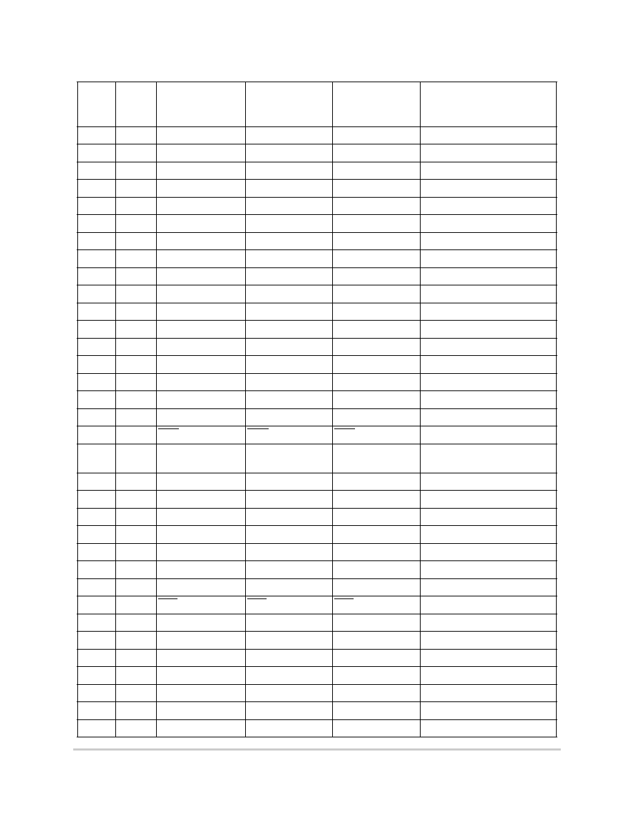
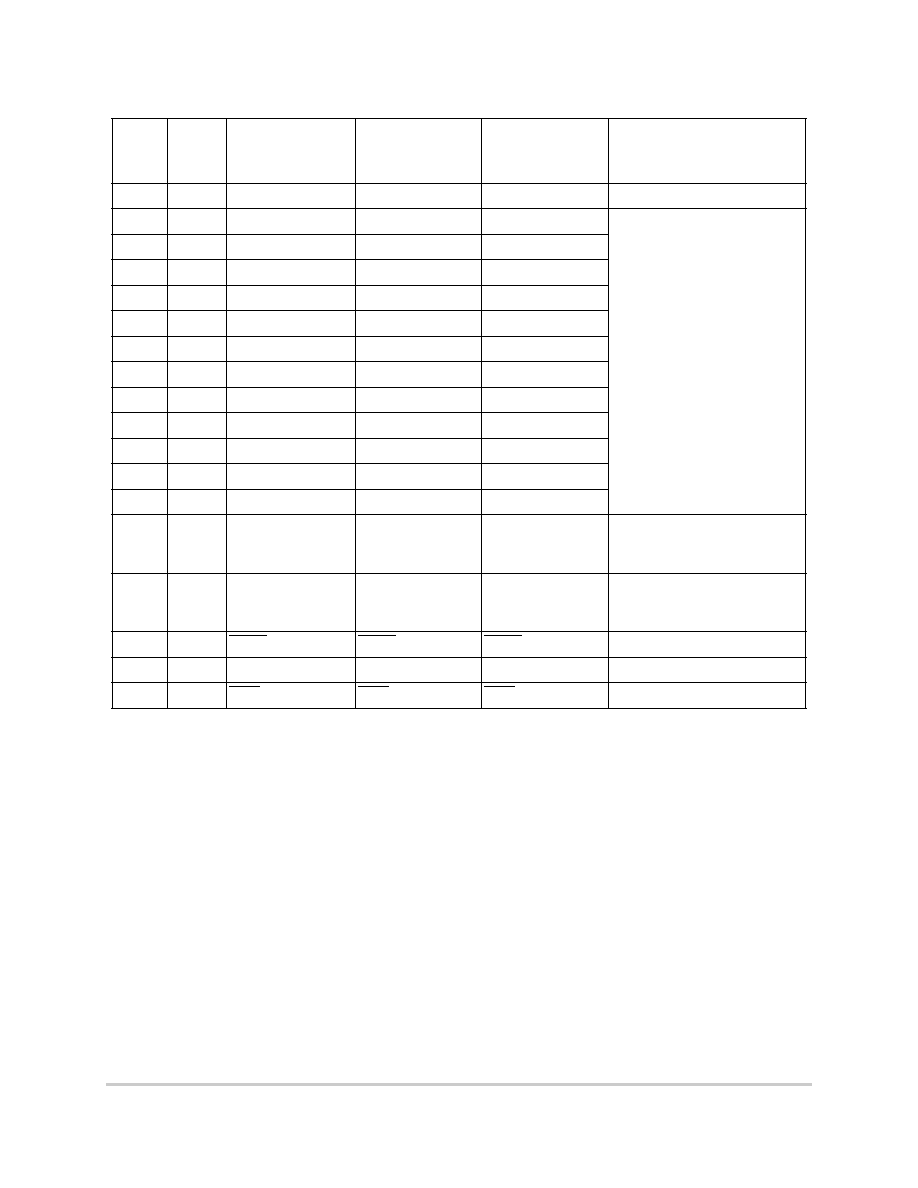
Main Pin Difference
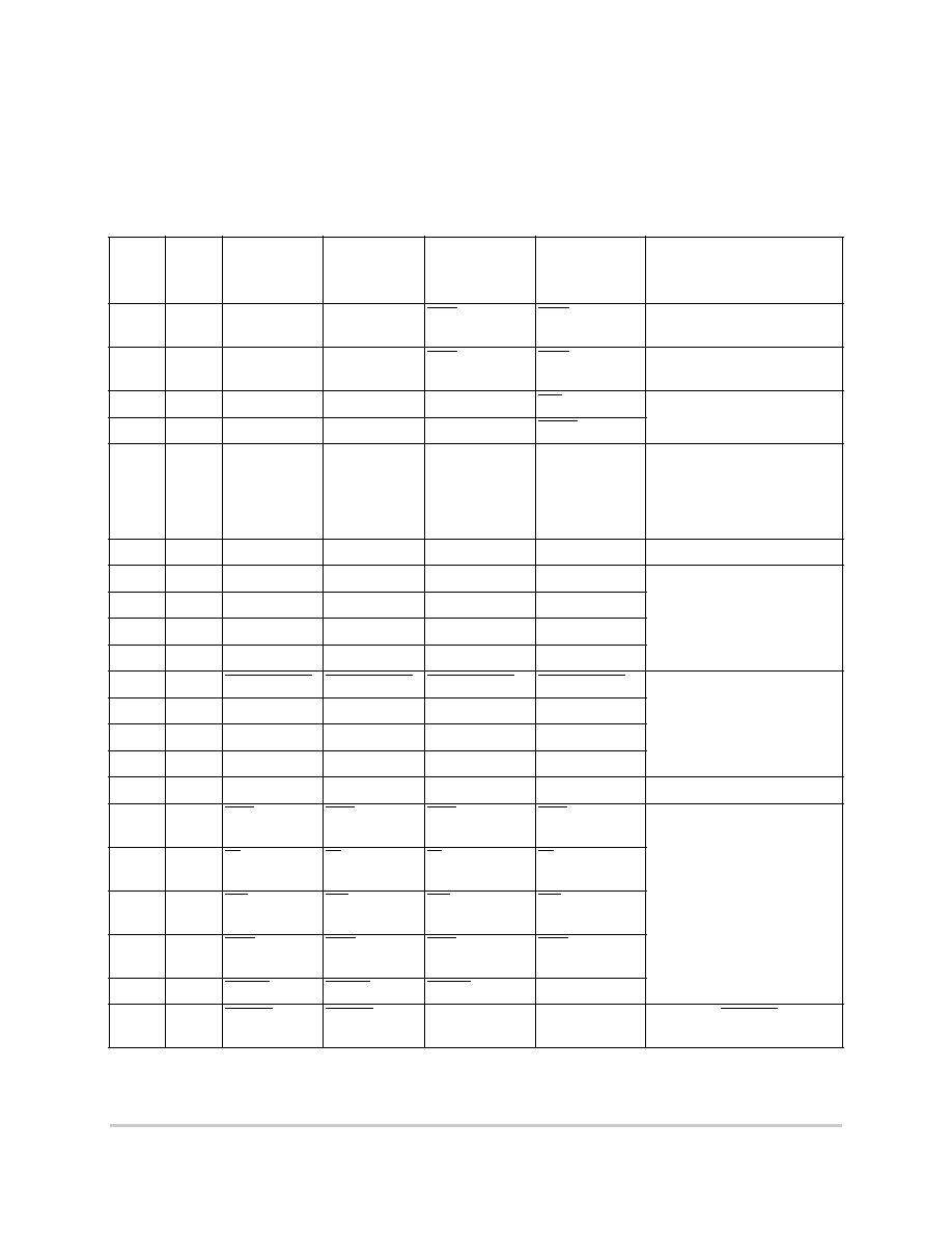
This section includes Table 1 which lists the main differences between the MPC750, MPC755, MPC7400
and MPC7410 and the configuration pins. The MPX bus column provides information for designers to take
advantage of the MPX bus mode for future board revisions.
Table 1. Main Pin Difference and Configuration Pins
Pin #
Type
MPC750
MPC755
MPC7400/
MPC7410
60x Bus
MPC7400/
MPC7410
MPX Bus
Comment
B3
I/O
No Connect
No Connect
SHD[0]
SHD[0]
Pull-up (in multi CPU system,
connect together)
1
B4
I/O
No Connect
No Connect
SHD[1]
SHD[1]
Pull-up (in multi CPU system,
connect together)
1
B5
Output
No Connect
No Connect
No Function
HIT
Pull-up to OVDD
1
K9
Output
No Connect
No Connect
No Function
DRDY
K19
Output
No Connect
No Connect
L2A17
L2A17
Connect to L2 SRAM. A pull-up
to L2VODD should be used if
MPC750/MPC755 1Mbyte
compatibility is required when
using 2Mbytes of SRAM.
W19
Output
No Connect
No Connect
L2A18
L2A18
Reserved for future expansion
A4
Input
PLL_CFG[0]
PLL_CFG[0]
PLL_CFG[0]
PLL_CFG[0]
See hardware specification
document. Should put in a pull
up/down pair for each to allow
any configuration.
A5
Input
PLL_CFG[1]
PLL_CFG[1]
PLL_CFG[1]
PLL_CFG[1]
A6
Input
PLL_CFG[2]
PLL_CFG[2]
PLL_CFG[2]
PLL_CFG[2]
A7
Input
PLL_CFG[3]
PLL_CFG[3]
PLL_CFG[3]
PLL_CFG[3]
F9
Input
LSSD_MODE
LSSD_MODE
LSSD_MODE
LSSD_MODE
Pull-up to OVDD
F7
Input
L2_TSTCLK
L2_TSTCLK
L2_TSTCLK
L2_TSTCLK
F8
Input
L1_TSTCLK
L1_TSTCLK
L1_TSTCLK
L1_TSTCLK
K11
Input
No Connect
No Connect
CHK
CHK
K13
VOLDET
VOLDET
L2OVDD[13]
L2OVDD[13]
Must be connected to L2OVDD
L7
I/O or
Output
ABB
ABB
ABB
ABB
Pull-up to OVDD
1
C2
I/O or
Output
CI
CI
CI
CI
C3
I/O or
Output
WT
WT
WT
WT
K5
I/O or
Output
DBB
DBB
DBB
DBB
D1
Input
DBWO
DBWO
DBWO
DTI[0]
2
H6
Input
DRTRY
DRTRY
No Function
DTI[1]
2
Connect to HRESET for no
Data retry mode in 60x bus.
F
r
e
e
s
c
a
l
e
S
e
m
i
c
o
n
d
u
c
t
o
r
,
I
Freescale Semiconductor, Inc.
For More Information On This Product,
Go to: www.freescale.com
n
c
.
.
.
MOTOROLA
Common Footprint for the MPC750, MPC755, MPC7400, and MPC7410
3
I/O Voltage Selection
1.2
I/O Voltage Selection
This section lists the four footprint power planes and displays the section matrix for the I/O voltages.
In addition, the footprint should have four power planes:
∑
Ground
∑
The CPU core voltage, [VDD]
∑
The I/O voltage for the system bus, [OVDD]
∑
The I/O voltage for the L2 SRAM interface, [L2OVDD]
The I/O voltages [OVDD and L2OVDD] are selectable on all the CPUs except the MPC750,
which supports 3.3V only on both of these interfaces.
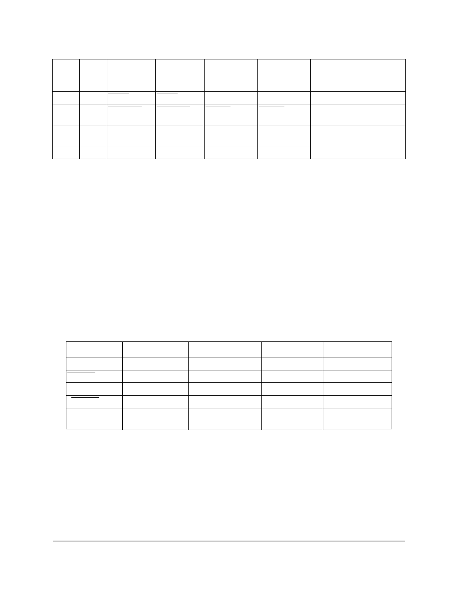
Table 2 and Table 3 show the selection matrix for the I/O voltages:
G1
Input
DBDIS
DBDIS
No Function
DTI[2]
2
Pull-up to OVDD
1
A3
Input
TLBISYNC
TLBISYNC
EMODE
EMODE
Pull-up to OVDD (64-bit 60x
bus)
W1
No Connect
BVSEL
BVSEL
BVSEL
See Table 2 and Table 3 for
voltages.
A19
No Connect
L2VSEL
L2VSEL
L2VSEL
1
See the individual hardware specifications document for the recommended resistor value.
2
DTI[0:2] should be pulled low in MPX bus mode to disable re-ordering.
Table 2. I/O Voltage Selection--BVSEL
BVSEL
MPC750
MPC755
MPC7400
MPC7410 (Rev E)
0
N/A
N/A
1.8V
1.8V
HRESET
N/A
N/A
N/A
2.5V
1
N/A
OVDD (2.5V/3.3V)
3.3V
3.3V
¨HRESET
N/A
N/A
N/A
3.3V
Unconnected
(internal pull-up)
N/A
2.5V/3.3V
3.3V
3.3V
Table 1. Main Pin Difference and Configuration Pins (continued)
Pin #
Type
MPC750
MPC755
MPC7400/
MPC7410
60x Bus
MPC7400/
MPC7410
MPX Bus
Comment
F
r
e
e
s
c
a
l
e
S
e
m
i
c
o
n
d
u
c
t
o
r
,
I
Freescale Semiconductor, Inc.
For More Information On This Product,
Go to: www.freescale.com
n
c
.
.
.
4
Common Footprint for the MPC750, MPC755, MPC7400, and MPC7410
MOTOROLA
I/O Voltage Selection
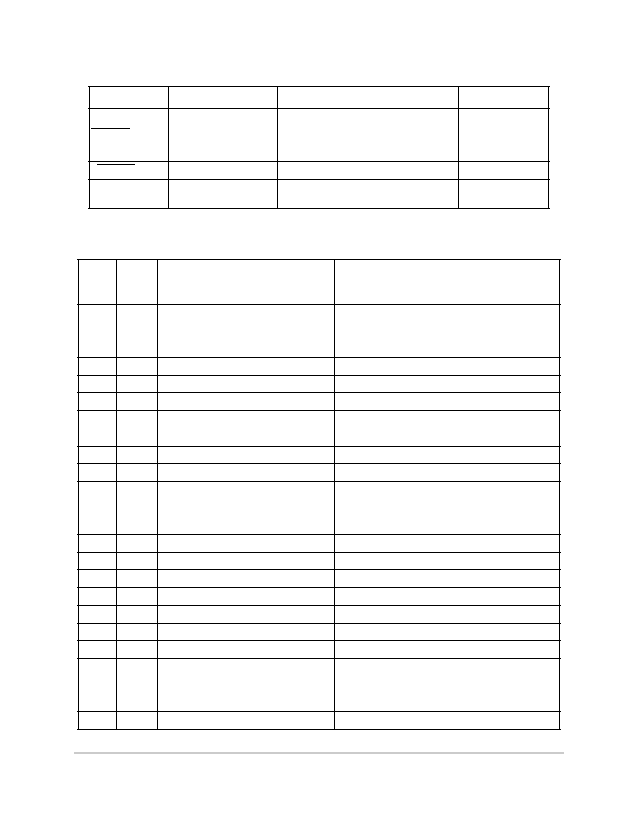
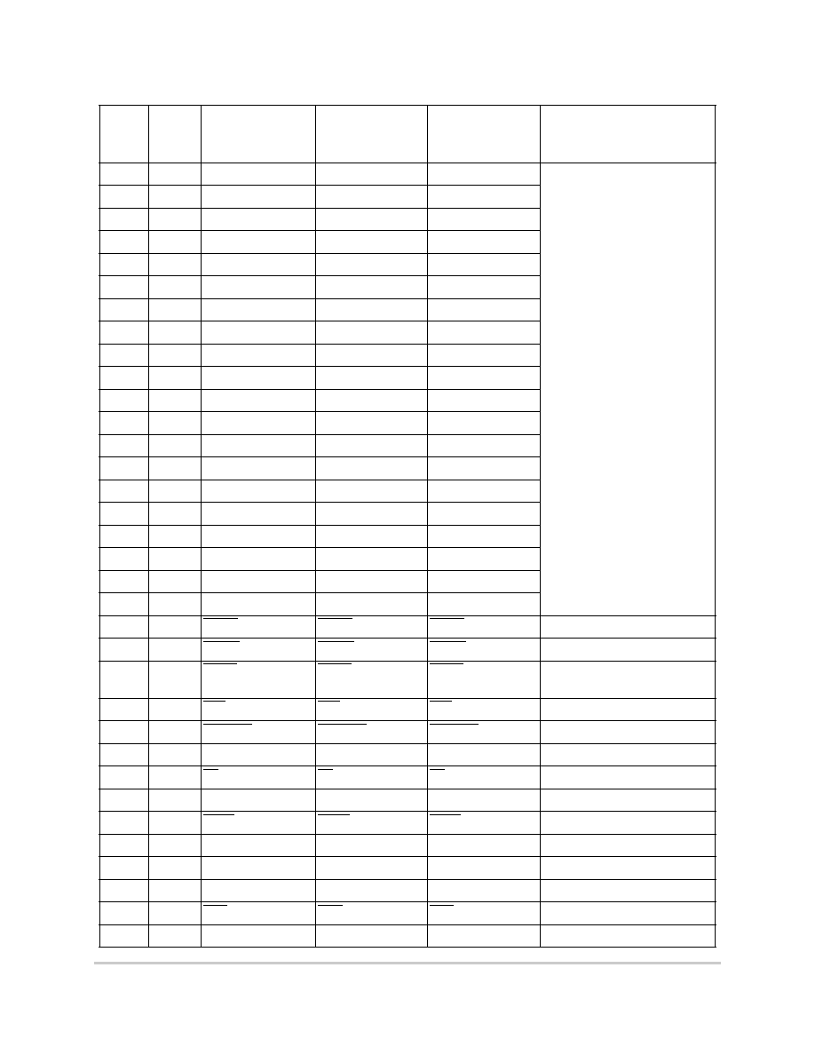
Table 4 pertains to the remaining pins, and the comments are valid for the common footprint.
Table 3. I/O Voltage Selection--L2VSEL
L2VSEL
MPC750
MPC755
MPC7400
MPC7410 (Rev E)
0
N/A
N/A
1.8V
1.8V
HRESET
N/A
N/A
2.5V
2.5V
1
N/A
L2VDD (2.5V/3.3V)
3.3V
2.5V
¨HRESET
N/A
N/A
N/A
N/A
Unconnected
(internal pull-up)
N/A
2.5V/3.3V
3.3V
2.5V
Table 4. Remaining Pins
Pin #
Type
MPC750
MPC755
MPC7400/
MPC7410
60x or MPX Bus
Comment
A13
I/O
A[00]
A[00]
A[00]
D2
I/O
A[01]
A[01]
A[01]
H11
I/O
A[02]
A[02]
A[02]
C1
I/O
A[03]
A[03]
A[03]
B13
I/O
A[04]
A[04]
A[04]
F2
I/O
A[05]
A[05]
A[05]
C13
I/O
A[06]
A[06]
A[06]
E5
I/O
A[07]
A[07]
A[07]
D13
I/O
A[08]
A[08]
A[08]
G7
I/O
A[09]
A[09]
A[09]
F12
I/O
A[10]
A[10]
A[10]
G3
I/O
A[11]
A[11]
A[11]
G6
I/O
A[12]
A[12]
A[12]
H2
I/O
A[13]
A[13]
A[13]
E2
I/O
A[14]
A[14]
A[14]
L3
I/O
A[15]
A[15]
A[15]
G5
I/O
A[16]
A[16]
A[16]
L4
I/O
A[17]
A[17]
A[17]
G4
I/O
A[18]
A[18]
A[18]
J4
I/O
A[19]
A[19]
A[19]
H7
I/O
A[20]
A[20]
A[20]
E1
I/O
A[21]
A[21]
A[21]
G2
I/O
A[22]
A[22]
A[22]
F3
I/O
A[23]
A[23]
A[23]
F
r
e
e
s
c
a
l
e
S
e
m
i
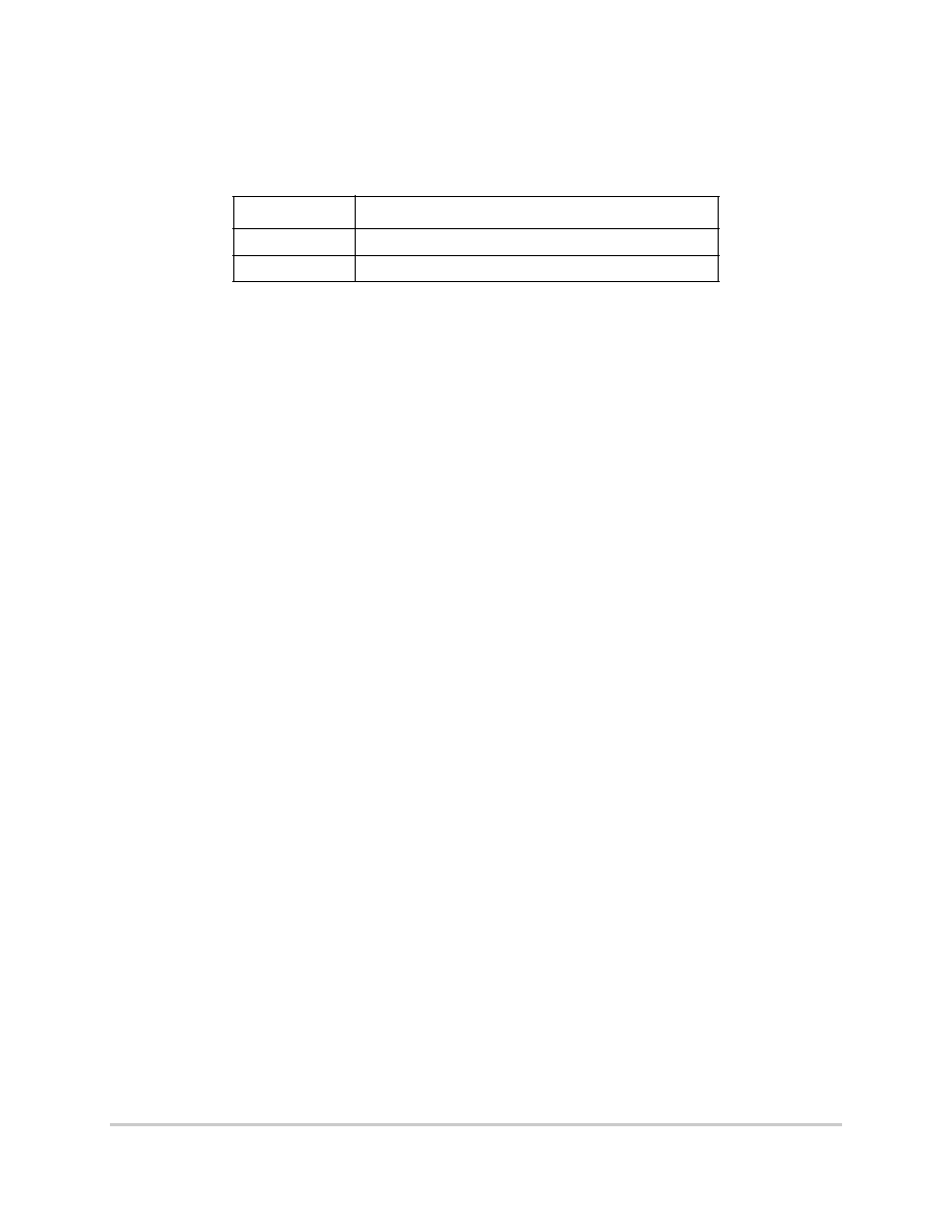
c
o
n
d
u
c
t
o
r
,
I
Freescale Semiconductor, Inc.
For More Information On This Product,
Go to: www.freescale.com
n
c
.
.
.

MOTOROLA
Common Footprint for the MPC750, MPC755, MPC7400, and MPC7410
5
I/O Voltage Selection
J7
I/O
A[24]
A[24]
A[24]
M3
I/O
A[25]
A[25]
A[25]
H3
I/O
A[26]
A[26]
A[26]
J2
I/O
A[27]
A[27]
A[27]
J6
I/O
A[28]
A[28]
A[28]
K3
I/O
A[29]
A[29]
A[29]
K2
I/O
A[30]
A[30]
A[30]
L2
I/O
A[31]
A[31]
A[31]
N3
Input
AACK
AACK
AACK
Pull up to OVDD
1
C4
I/O
AP[0]
AP[0]
AP[0]
Pulled up to OVDD if not used to
reduce noise and power.
C5
I/O
AP[1]
AP[1]
AP[1]
C6
I/O
AP[2]
AP[2]
AP[2]
C7
I/O
AP[3]
AP[3]
AP[3]
L6
I/O
ARTRY
ARTRY
ARTRY
Pull up to OVDD
1
A8
AVDD
AVDD
AVDD
Use filter circuit
2
H1
Input
BG
BG
BG
Pull down if no other master.
E7
Output
BR
BR
BR
C2
Output
CI
CI
CI
B8
Input
CKSTP_IN
CKSTP_IN
CKSTP_IN
Pull up to OVDD
1
D7
Output
CKSTP_OUT
CKSTP_OUT
CKSTP_OUT
E3
Output
CLKOUT
CLKOUT
CLKOUT
W12
I/O
DH[00]
DH[00]
D[00]
W11
I/O
DH[01]
DH[01]
D[01]
V11
I/O
DH[02]
DH[02]
D[02]
T9
I/O
DH[03]
DH[03]
D[03]
W10
I/O
DH[04]
DH[04]
D[04]
U9
I/O
DH[05]
DH[05]
D[05]
U10
I/O
DH[06]
DH[06]
D[06]
M11
I/O
DH[07]
DH[07]
D[07]
M9
I/O
DH[08]
DH[08]
D[08]
P8
I/O
DH[09]
DH[09]
D[09]
W7
I/O
DH[10]
DH[10]
D[10]
P9
I/O
DH[11]
DH[11]
D[11]
W9
I/O
DH[12]
DH[12]
D[12]
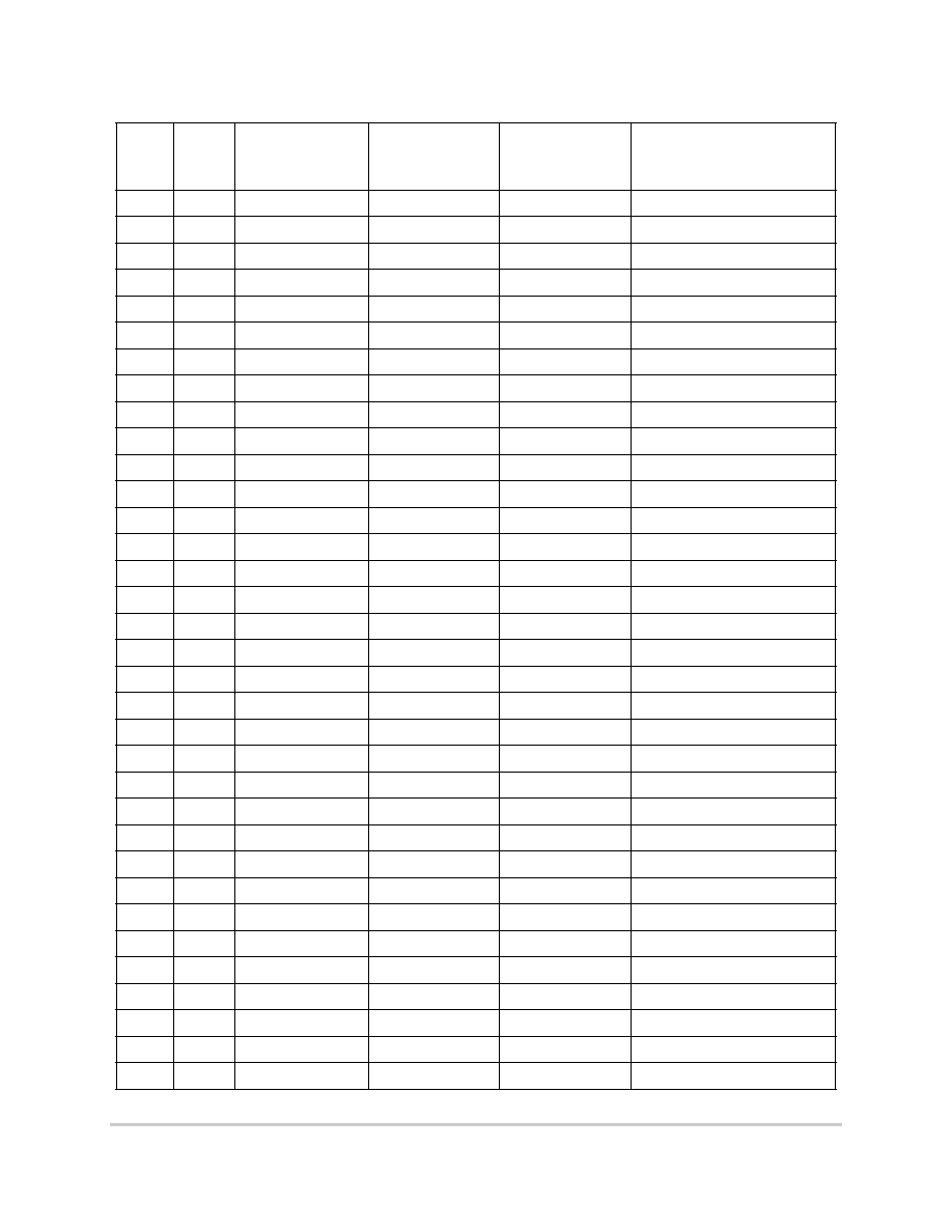
Table 4. Remaining Pins (continued)
Pin #
Type
MPC750
MPC755
MPC7400/
MPC7410
60x or MPX Bus
Comment
F
r
e
e
s
c
a
l
e
S
e
m
i
c
o
n
d
u
c
t
o
r
,
I
Freescale Semiconductor, Inc.
For More Information On This Product,
Go to: www.freescale.com
n
c
.
.
.
6
Common Footprint for the MPC750, MPC755, MPC7400, and MPC7410
MOTOROLA
I/O Voltage Selection
R10
I/O
DH[13]
DH[13]
D[13]
W6
I/O
DH[14]
DH[14]
D[14]
V7
I/O
DH[15]
DH[15]
D[15]
V6
I/O
DH[16]
DH[16]
D[16]
U8
I/O
DH[17]
DH[17]
D[17]
V9
I/O
DH[18]
DH[18]
D[18]
T7
I/O
DH[19]
DH[19]
D[19]
U7
I/O
DH[20]
DH[20]
D[20]
R7
I/O
DH[21]
DH[21]
D[21]
U6
I/O
DH[22]
DH[22]
D[22]
W5
I/O
DH[23]
DH[23]
D[23]
U5
I/O
DH[24]
DH[24]
D[24]
W4
I/O
DH[25]
DH[25]
D[25]
P7
I/O
DH[26]
DH[26]
D[26]
V5
I/O
DH[27]
DH[27]
D[27]
V4
I/O
DH[28]
DH[28]
D[28]
W3
I/O
DH[29]
DH[29]
D[29]
U4
I/O
DH[30]
DH[30]
D[30]
R5
I/O
DH[31]
DH[31]
D[31]
M6
I/O
DL[00]
DL[00]
D[32]
P3
I/O
DL[01]
DL[01]
D[33]
N4
I/O
DL[02]
DL[02]
D[34]
N5
I/O
DL[03]
DL[03]
D[35]
R3
I/O
DL[04]
DL[04]
D[36]
M7
I/O
DL[05]
DL[05]
D[37]
T2
I/O
DL[06]
DL[06]
D[38]
N6
I/O
DL[07]
DL[07]
D[39]
U2
I/O
DL[08]
DL[08]
D[40]
N7
I/O
DL[09]
DL[09]
D[41]
P11
I/O
DL[10]
DL[10]
D[42]
V13
I/O
DL[11]
DL[11]
D[43]
U12
I/O
DL[12]
DL[12]
D[44]
P12
I/O
DL[13]
DL[13]
D[45]
T13
I/O
DL[14]
DL[14]
D[46]
Table 4. Remaining Pins (continued)
Pin #
Type
MPC750
MPC755
MPC7400/
MPC7410
60x or MPX Bus
Comment
F
r
e
e
s
c
a
l
e
S
e
m
i
c
o
n
d
u
c
t
o
r
,
I
Freescale Semiconductor, Inc.
For More Information On This Product,
Go to: www.freescale.com
n
c
.
.
.
MOTOROLA
Common Footprint for the MPC750, MPC755, MPC7400, and MPC7410
7
I/O Voltage Selection
W13
I/O
DL[15]
DL[15]
D[47]
U13
I/O
DL[16]
DL[16]
D[48]
V10
I/O
DL[17]
DL[17]
D[49]
W8
I/O
DL[18]
DL[18]
D[50]
T11
I/O
DL[19]
DL[19]
D[51]
U11
I/O
DL[20]
DL[20]
D[52]
V12
I/O
DL[21]
DL[21]
D[53]
V8
I/O
DL[22]
DL[22]
D[54]
TU1
I/O
DL[23]
DL[23]
D[55]
P1
I/O
DL[24]
DL[24]
D[56]
V1
I/O
DL[25]
DL[25]
D[57]
U1
I/O
DL[26]
DL[26]
D[58]
N1
I/O
DL[27]
DL[27]
D[59]
R2
I/O
DL[28]
DL[28]
D[60]
V3
I/O
DL[29]
DL[29]
D[61]
U3
I/O
DL[30]
DL[30]
D[62]
W2
I/O
DL[31]
DL[31]
D[63]
K1
Input
DBG
DBG
DBG
Pull down if no other masters
L1
I/O
DP[0]
DP[0]
DP[0]
Pulled up if not used to reduce
noise and power.
P2
I/O
DP[1]
DP[1]
DP[1]
M2
I/O
DP[2]
DP[2]
DP[2]
V2
I/O
DP[3]
DP[3]
DP[3]
M1
I/O
DP[4]
DP[4]
DP[4]
N2
I/O
DP[5]
DP[5]
DP[5]
T3
I/O
DP[6]
DP[6]
DP[6]
R1
I/O
DP[7]
DP[7]
DP[7]
B1
I/O
GBL
GBL
GBL
Pull up
1
D10
GND[01]
GND[01]
GND[01]
Ground for the device
D14
GND[02]
GND[02]
GND[02]
D16
GND[03]
GND[03]
GND[03]
D4
GND[04]
GND[04]
GND[04]
D6
GND[05]
GND[05]
GND[05]
E12
GND[06]
GND[06]
GND[06]
E8
GND[07]
GND[07]
GND[07]
Table 4. Remaining Pins (continued)
Pin #
Type
MPC750
MPC755
MPC7400/
MPC7410
60x or MPX Bus
Comment
F
r
e
e
s
c
a
l
e
S
e
m
i
c
o
n
d
u
c
t
o
r
,
I
Freescale Semiconductor, Inc.
For More Information On This Product,
Go to: www.freescale.com
n
c
.
.
.

8
Common Footprint for the MPC750, MPC755, MPC7400, and MPC7410
MOTOROLA
I/O Voltage Selection
F4
GND[08]
GND[08]
GND[08]
F6
GND[09]
GND[09]
GND[09]
F10
GND[10]
GND[10]
GND[10]
F14
GND[11]
GND[11]
GND[11]
F16
GND[12]
GND[12]
GND[12]
G9
GND[13]
GND[13]
GND[13]
G11
GND[14]
GND[14]
GND[14]
H5
GND[15]
GND[15]
GND[15]
H8
GND[16]
GND[16]
GND[16]
H10
GND[17]
GND[17]
GND[17]
H12
GND[18]
GND[18]
GND[18]
H15
GND[19]
GND[19]
GND[19]
J9
GND[20]
GND[20]
GND[20]
J11
GND[21]
GND[21]
GND[21]
K4
GND[22]
GND[22]
GND[22]
K6
GND[23]
GND[23]
GND[23]
K8
GND[24]
GND[24]
GND[24]
K10
GND[25]
GND[25]
GND[25]
K12
GND[26]
GND[26]
GND[26]
K14
GND[27]
GND[27]
GND[27]
K16
GND[28]
GND[28]
GND[28]
L9
GND[29]
GND[29]
GND[29]
L11
GND[30]
GND[30]
GND[30]
M5
GND[31]
GND[31]
GND[31]
M8
GND[32]
GND[32]
GND[32]
M10
GND[33]
GND[33]
GND[33]
M12
GND[34]
GND[34]
GND[34]
M15
GND[35]
GND[35]
GND[35]
N9
GND[36]
GND[36]
GND[36]
N11
GND[37]
GND[37]
GND[37]
P4
GND[38]
GND[38]
GND[38]
P6
GND[39]
GND[39]
GND[39]
P10
GND[40]
GND[40]
GND[40]
P14
GND[41]
GND[41]
GND[41]
Table 4. Remaining Pins (continued)
Pin #
Type
MPC750
MPC755
MPC7400/
MPC7410
60x or MPX Bus
Comment
F
r
e
e
s
c
a
l
e
S
e
m
i
c
o
n
d
u
c
t
o
r
,
I
Freescale Semiconductor, Inc.
For More Information On This Product,
Go to: www.freescale.com
n
c
.
.
.

MOTOROLA
Common Footprint for the MPC750, MPC755, MPC7400, and MPC7410
9
I/O Voltage Selection
P16
GND[42]
GND[42]
GND[42]
R8
GND[43]
GND[43]
GND[43]
R12
GND[44]
GND[44]
GND[44]
T4
GND[45]
GND[45]
GND[45]
T6
GND[46]
GND[46]
GND[46]
T10
GND[47]
GND[47]
GND[47]
T14
GND[48]
GND[48]
GND[48]
T16
GND[49]
GND[49]
GND[49]
B6
Input
HRESET
HRESET
HRESET
Driven constantly from reset
controller
C11
Input
INT
INT
INT
Pull up if not driven constantly
L17
Output
L2ADDR[0]
L2ADDR[0]
L2A[00]
L18
Output
L2ADDR[1]
L2ADDR[1]
L2A[01]
L19
Output
L2ADDR[2]
L2ADDR[2]
L2A[02]
M19
Output
L2ADDR[3]
L2ADDR[3]
L2A[03]
K18
Output
L2ADDR[4]
L2ADDR[4]
L2A[04]
K17
Output
L2ADDR[5]
L2ADDR[5]
L2A[05]
K15
Output
L2ADDR[6]
L2ADDR[6]
L2A[06]
J19
Output
L2ADDR[7]
L2ADDR[7]
L2A[07]
J18
Output
L2ADDR[8]
L2ADDR[8]
L2A[08]
J17
Output
L2ADDR[9]
L2ADDR[9]
L2A[09]
J16
Output
L2ADDR[10]
L2ADDR[10]
L2A[10]
H18
Output
L2ADDR[11]
L2ADDR[11]
L2A[11]
H17
Output
L2ADDR[12]
L2ADDR[12]
L2A[12]
J14
Output
L2ADDR[13]
L2ADDR[13]
L2A[13]
J13
Output
L2ADDR[14]
L2ADDR[14]
L2A[14]
H19
Output
L2ADDR[15]
L2ADDR[15]
L2A[15]
G18
Output
L2ADDR[16]
L2ADDR[16]
L2A[16]
L13
L2AVDD
L2AVDD
L2AVDD
Use filter circuit
2
P17
Output
L2CE
L2CE
L2CE
N15
Output
L2CLKOUTA
L2CLKOUTA
L2CLKOUTA
L16
Output
L2CLKOUTB
L2CLKOUTB
L2CLKOUTB
U14
I/O
L2DATA[0]
L2DATA[0]
L2D[00]
R13
I/O
L2DATA[1]
L2DATA[1]
L2D[01]
W14
I/O
L2DATA[2]
L2DATA[2]
L2D[02]
Table 4. Remaining Pins (continued)
Pin #
Type
MPC750
MPC755
MPC7400/
MPC7410
60x or MPX Bus
Comment
F
r
e
e
s
c
a
l
e
S
e
m
i
c
o
n
d
u
c
t
o
r
,
I
Freescale Semiconductor, Inc.
For More Information On This Product,
Go to: www.freescale.com
n
c
.
.
.

10
Common Footprint for the MPC750, MPC755, MPC7400, and MPC7410
MOTOROLA
I/O Voltage Selection
W15
I/O
L2DATA[3]
L2DATA[3]
L2D[03]
V15
I/O
L2DATA[4]
L2DATA[4]
L2D[04]
U15
I/O
L2DATA[5]
L2DATA[5]
L2D[05]
W16
I/O
L2DATA[6]
L2DATA[6]
L2D[06]
V16
I/O
L2DATA[7]
L2DATA[7]
L2D[07]
W17
I/O
L2DATA[8]
L2DATA[8]
L2D[08]
V17
I/O
L2DATA[9]
L2DATA[9]
L2D[09]
U17
I/O
L2DATA[10]
L2DATA[10]
L2D[10]
W18
I/O
L2DATA[11]
L2DATA[11]
L2D[11]
V18
I/O
L2DATA[12]
L2DATA[12]
L2D[12]
U18
I/O
L2DATA[13]
L2DATA[13]
L2D[13]
V19
I/O
L2DATA[14]
L2DATA[14]
L2D[14]
U19
I/O
L2DATA[15]
L2DATA[15]
L2D[15]
T18
I/O
L2DATA[16]
L2DATA[16]
L2D[16]
T17
I/O
L2DATA[17]
L2DATA[17]
L2D[17]
R19
I/O
L2DATA[18]
L2DATA[18]
L2D[18]
R18
I/O
L2DATA[19]
L2DATA[19]
L2D[19]
R17
I/O
L2DATA[20]
L2DATA[20]
L2D[20]
R15
I/O
L2DATA[21]
L2DATA[21]
L2D[21]
P19
I/O
L2DATA[22]
L2DATA[22]
L2D[22]
P18
I/O
L2DATA[23]
L2DATA[23]
L2D[23]
P13
I/O
L2DATA[24]
L2DATA[24]
L2D[24]
N14
I/O
L2DATA[25]
L2DATA[25]
L2D[25]
N13
I/O
L2DATA[26]
L2DATA[26]
L2D[26]
N19
I/O
L2DATA[27]
L2DATA[27]
L2D[27]
N17
I/O
L2DATA[28]
L2DATA[28]
L2D[28]
M17
I/O
L2DATA[29]
L2DATA[29]
L2D[29]
M13
I/O
L2DATA[30]
L2DATA[30]
L2D[30]
M18
I/O
L2DATA[31]
L2DATA[31]
L2D[31]
H13
I/O
L2DATA[32]
L2DATA[32]
L2D[32]
G19
I/O
L2DATA[33]
L2DATA[33]
L2D[33]
G16
I/O
L2DATA[34]
L2DATA[34]
L2D[34]
G15
I/O
L2DATA[35]
L2DATA[35]
L2D[35]
G14
I/O
L2DATA[36]
L2DATA[36]
L2D[36]
Table 4. Remaining Pins (continued)
Pin #
Type
MPC750
MPC755
MPC7400/
MPC7410
60x or MPX Bus
Comment
F
r
e
e
s
c
a
l
e
S
e
m
i
c
o
n
d
u
c
t
o
r
,
I
Freescale Semiconductor, Inc.
For More Information On This Product,
Go to: www.freescale.com
n
c
.
.
.

MOTOROLA
Common Footprint for the MPC750, MPC755, MPC7400, and MPC7410
11
I/O Voltage Selection
G13
I/O
L2DATA[37]
L2DATA[37]
L2D[37]
F19
I/O
L2DATA[38]
L2DATA[38]
L2D[38]
F18
I/O
L2DATA[39]
L2DATA[39]
L2D[39]
F13
I/O
L2DATA[40]
L2DATA[40]
L2D[40]
E19
I/O
L2DATA[41]
L2DATA[41]
L2D[41]
E18
I/O
L2DATA[42]
L2DATA[42]
L2D[42]
E17
I/O
L2DATA[43]
L2DATA[43]
L2D[43]
E15
I/O
L2DATA[44]
L2DATA[44]
L2D[44]
D19
I/O
L2DATA[45]
L2DATA[45]
L2D[45]
D18
I/O
L2DATA[46]
L2DATA[46]
L2D[46]
D17
I/O
L2DATA[47]
L2DATA[47]
L2D[47]
C18
I/O
L2DATA[48]
L2DATA[48]
L2D[48]
C17
I/O
L2DATA[49]
L2DATA[49]
L2D[49]
B19
I/O
L2DATA[50]
L2DATA[50]
L2D[50]
B18
I/O
L2DATA[51]
L2DATA[51]
L2D[51]
B17
I/O
L2DATA[52]
L2DATA[52]
L2D[52]
A18
I/O
L2DATA[53]
L2DATA[53]
L2D[53]
A17
I/O
L2DATA[54]
L2DATA[54]
L2D[54]
A16
I/O
L2DATA[55]
L2DATA[55]
L2D[55]
B16
I/O
L2DATA[56]
L2DATA[56]
L2D[56]
C16
I/O
L2DATA[57]
L2DATA[57]
L2D[57]
A14
I/O
L2DATA[58]
L2DATA[58]
L2D[58]
A15
I/O
L2DATA[59]
L2DATA[59]
L2D[59]
C15
I/O
L2DATA[60]
L2DATA[60]
L2D[60]
B14
I/O
L2DATA[61]
L2DATA[61]
L2D[61]
C14
I/O
L2DATA[62]
L2DATA[62]
L2D[62]
E13
I/O
L2DATA[63]
L2DATA[63]
L2D[63]
V14
I/O
L2DP[0]
L2DP[0]
L2DP[0]
U16
I/O
L2DP[1]
L2DP[1]
L2DP[1]
T19
I/O
L2DP[2]
L2DP[2]
L2DP[2]
N18
I/O
L2DP[3]
L2DP[3]
L2DP[3]
H14
I/O
L2DP[4]
L2DP[4]
L2DP[4]
F17
I/O
L2DP[5]
L2DP[5]
L2DP[5]
C19
I/O
L2DP[6]
L2DP[6]
L2DP[6]
Table 4. Remaining Pins (continued)
Pin #
Type
MPC750
MPC755
MPC7400/
MPC7410
60x or MPX Bus
Comment
F
r
e
e
s
c
a
l
e
S
e
m
i
c
o
n
d
u
c
t
o
r
,
I
Freescale Semiconductor, Inc.
For More Information On This Product,
Go to: www.freescale.com
n
c
.
.
.
12
Common Footprint for the MPC750, MPC755, MPC7400, and MPC7410
MOTOROLA
I/O Voltage Selection
B15
I/O
L2DP[7]
L2DP[7]
L2DP[7]
D15
L2OVDD[01]
L2OVDD[01]
L2OVDD[01]
Level 2 cache I/O voltage
E14
L2OVDD[02]
L2OVDD[02]
L2OVDD[02]
E16
L2OVDD[03]
L2OVDD[03]
L2OVDD[03]
H16
L2OVDD[04]
L2OVDD[04]
L2OVDD[04]
J15
L2OVDD[05]
L2OVDD[05]
L2OVDD[05]
L15
L2OVDD[06]
L2OVDD[06]
L2OVDD[06]
M16
L2OVDD[07]
L2OVDD[07]
L2OVDD[07]
P15
L2OVDD[08]
L2OVDD[08]
L2OVDD[08]
R14
L2OVDD[09]
L2OVDD[09]
L2OVDD[09]
R16
L2OVDD[10]
L2OVDD[10]
L2OVDD[10]
T15
L2OVDD[11]
L2OVDD[11]
L2OVDD[11]
F15
L2OVDD[12]
L2OVDD[12]
L2OVDD[12]
L14
Input
L2SYNC_IN
L2SYNC_IN
L2SYNC_IN
Connected to L2SYNC_OUT
with a trace length equal to the
address and data for L2 SRAMs
M14
Output
L2SYNC_OUT
L2SYNC_OUT
L2SYNC_OUT
Connected to L2SYNC_IN with
a trace length equal to the
address and data for L2 SRAMs
N16
L2WE
L2WE
L2WE
G17
L2ZZ
L2ZZ
L2ZZ
B11
MCP
MCP
MCP
Table 4. Remaining Pins (continued)
Pin #
Type
MPC750
MPC755
MPC7400/
MPC7410
60x or MPX Bus
Comment
F
r
e
e
s
c
a
l
e
S
e
m
i
c
o
n
d
u
c
t
o
r
,
I
Freescale Semiconductor, Inc.
For More Information On This Product,
Go to: www.freescale.com
n
c
.
.
.
13
Common Footprint for the MPC750, MPC755, MPC7400, and MPC7410
MOTOROLA
I/O Voltage Selection
D5
OVDD[00]
OVDD[00]
OVDD[00]
System bus I/O voltage.
D8
OVDD[01]
OVDD[01]
OVDD[01]
D12
OVDD[02]
OVDD[02]
OVDD[02]
E4
OVDD[03]
OVDD[03]
OVDD[03]
E6
OVDD[04]
OVDD[04]
OVDD[04]
E9
OVDD[05]
OVDD[05]
OVDD[05]
E11
OVDD[06]
OVDD[06]
OVDD[06]
F5
OVDD[07]
OVDD[07]
OVDD[07]
H4
OVDD[08]
OVDD[08]
OVDD[08]
J5
OVDD[09]
OVDD[09]
OVDD[09]
L5
OVDD[10]
OVDD[10]
OVDD[10]
M4
OVDD[11]
OVDD[11]
OVDD[11]
P5
OVDD[12]
OVDD[12]
OVDD[12]
R4
OVDD[13]
OVDD[13]
OVDD[13]
R6
OVDD[14]
OVDD[14]
OVDD[14]
R9
OVDD[15]
OVDD[15]
OVDD[15]
R11
OVDD[16]
OVDD[16]
OVDD[16]
T5
OVDD[17]
OVDD[17]
OVDD[17]
T8
OVDD[18]
OVDD[18]
OVDD[18]
T12
OVDD[19]
OVDD[19]
OVDD[19]
B2
Input
QACK
QACK
QACK
Pull up if unused
1
J3
Output
QREQ
QREQ
QREQ
D3
Output
RSRV
RSRV
RSRV
Put to test point useful for
debug.
A12
Input
SMI
SMI
SMI
Pull up if not driven constantly
1
E10
Input
SRESET
SRESET
SRESET
Pull up if not driven constantly
1
H9
Input
SYSCLK
SYSCLK
SYSCLK
F1
Input
TA
TA
TA
Pull up
1
A2
Input
TBEN
TBEN
TBEN
Pull up if not driven constantly
1
A11
I/O
TBST
TBST
TBST
Pull up
1
B10
Input
TCK
TCK
TCK
B7
Input
TDI
TDI
TDI
D9
Output
TD0
TD0
TD0
J1
Input
TEA
TEA
TEA
Pull up
1
C8
Input
TMS
TMS
TMS
Pull up
Table 4. Remaining Pins (continued)
Pin #
Type
MPC750
MPC755
MPC7400/
MPC7410
60x or MPX Bus
Comment
F
r
e
e
s
c
a
l
e
S
e
m
i
c
o
n
d
u
c
t
o
r
,
I
Freescale Semiconductor, Inc.
For More Information On This Product,
Go to: www.freescale.com
n
c
.
.
.

14
Common Footprint for the MPC750, MPC755, MPC7400, and MPC7410
MOTOROLA
I/O Voltage Selection
A10
Input
TRST
TRST
TRST
Connect to HRESET directly if
JTAG or COP not used or via
logic.
K7
I/O
TS
TS
TS
Pull up
1
A9
Output
TSIZ[0]
TSIZ[0]
TSIZ[0]
B9
Output
TSIZ[1]
TSIZ[1]
TSIZ[1]
C9
Output
TSIZ[2]
TSIZ[2]
TSIZ[2]
C10
I/O
TT[0]
TT[0]
TT[0]
Pull up
1
D11
I/O
TT[1]
TT[1]
TT[1]
B12
I/O
TT[2]
TT[2]
TT[2]
C12
I/O
TT[3]
TT[3]
TT[3]
F11
I/O
TT[4]
TT[4]
TT[4]
C3
Output
WT
WT
WT
G8
VDD[00]
VDD[00]
VDD[00]
CPU core voltage
G10
VDD[01]
VDD[01]
VDD[01]
G12
VDD[02]
VDD[02]
VDD[02]
J8
VDD[03]
VDD[03]
VDD[03]
J10
VDD[04]
VDD[04]
VDD[04]
J12
VDD[05]
VDD[05]
VDD[05]
L8
VDD[06]
VDD[06]
VDD[06]
L10
VDD[07]
VDD[07]
VDD[07]
L12
VDD[08]
VDD[08]
VDD[08]
N8
VDD[09]
VDD[09]
VDD[09]
N10
VDD[10]
VDD[10]
VDD[10]
N12
VDD[11]
VDD[11]
VDD[11]
1
See the individual hardware specifications document for the recommended resistor value.
2
See the individual hardware specifications document for more information.
Table 4. Remaining Pins (continued)
Pin #
Type
MPC750
MPC755
MPC7400/
MPC7410
60x or MPX Bus
Comment
F
r
e
e
s
c
a
l
e
S
e
m
i
c
o
n
d
u
c
t
o
r
,
I
Freescale Semiconductor, Inc.
For More Information On This Product,
Go to: www.freescale.com
n
c
.
.
.
15
Common Footprint for the MPC750, MPC755, MPC7400, and MPC7410
MOTOROLA
Revision History
1.3
Revision History
Table 5 shows this document's revision history.
Table 5. Document Revision History
Revision Number
Significant Changes
0, 0.1
Internal releases
1
Initial public release
F
r
e
e
s
c
a
l
e
S
e
m
i
c
o
n
d
u
c
t
o
r
,
I
Freescale Semiconductor, Inc.
For More Information On This Product,
Go to: www.freescale.com
n
c
.
.
.

AN1812/D
HOW TO REACH US:
USA/EUROPE/LOCATIONS NOT LISTED:
Motorola Literature Distribution;
P.O. Box 5405, Denver, Colorado 80217
1-303-675-2140 or 1-800-441-2447
JAPAN:
Motorola Japan Ltd.;
SPS, Technical Information Center,
3-20-1, Minami-Azabu Minato-ku,
Tokyo 106-8573 Japan
81-3-3440-3569
ASIA/PACIFIC:
Motorola Semiconductors H.K. Ltd.;
Silicon Harbour Centre, 2 Dai King Street,
Tai Po Industrial Estate, Tai Po, N.T., Hong Kong
852-26668334
TECHNICAL INFORMATION CENTER:
1-800-521-6274
HOME PAGE:
http://www.motorola.com/semiconductors
DOCUMENT COMMENTS:
FAX (512) 933-2625,
Attn: RISC Applications Engineering
Information in this document is provided solely to enable system and software implementers to use
Motorola products. There are no express or implied copyright licenses granted hereunder to design
or fabricate any integrated circuits or integrated circuits based on the information in this document.
Motorola reserves the right to make changes without further notice to any products herein.
Motorola makes no warranty, representation or guarantee regarding the suitability of its products
for any particular purpose, nor does Motorola assume any liability arising out of the application or
use of any product or circuit, and specifically disclaims any and all liability, including without
limitation consequential or incidental damages. "Typical" parameters which may be provided in
Motorola data sheets and/or specifications can and do vary in different applications and actual
performance may vary over time. All operating parameters, including "Typicals" must be validated
for each customer application by customer's technical experts. Motorola does not convey any
license under its patent rights nor the rights of others. Motorola products are not designed,
intended, or authorized for use as components in systems intended for surgical implant into the
body, or other applications intended to support or sustain life, or for any other application in which
the failure of the Motorola product could create a situation where personal injury or death may
occur. Should Buyer purchase or use Motorola products for any such unintended or unauthorized
application, Buyer shall indemnify and hold Motorola and its officers, employees, subsidiaries,
affiliates, and distributors harmless against all claims, costs, damages, and expenses, and
reasonable attorney fees arising out of, directly or indirectly, any claim of personal injury or death
associated with such unintended or unauthorized use, even if such claim alleges that Motorola was
negligent regarding the design or manufacture of the part.
Motorola and the Stylized M Logo are registered in the U.S. Patent and Trademark Office.
digital dna is a trademark of Motorola, Inc. All other product or service names are the property of
their respective owners. Motorola, Inc. is an Equal Opportunity/Affirmative Action Employer.
© Motorola, Inc. 2001
F
r
e
e
s
c
a
l
e
S
e
m
i
c
o
n
d
u
c
t
o
r
,
I
Freescale Semiconductor, Inc.
For More Information On This Product,
Go to: www.freescale.com
n
c
.
.
.