
DSP56824/D
Rev. 2.0, 01/2000
Semiconductor Products Sector
© Motorola, Inc., 2000. All rights reserved.
DSP56824
Technical Data
DSP56824 16-Bit Digital Signal Processor
The DSP56824 is a member of the DSP56800 core-based family of Digital Signal Processors (DSPs). This
general purpose DSP combines processing power with configuration flexibility, making it an excellent
cost-effective solution for signal processing and control functions. Because of its low cost, configuration
flexibility, and compact program code, the DSP56824 is well-suited for cost-sensitive applications, such as
digital wireless messaging, digital answering machines/feature phones, modems, and digital cameras. The
DSP56800 core consists of three execution units operating in parallel, allowing as many as six operations
per instruction cycle. The MPU-style programming model and optimized instruction set allow
straightforward generation of efficient, compact DSP and control code. The instruction set is also highly
efficient for C Compilers. The DSP56824 supports program execution from either internal or external
memories. Two data operands can be accessed from the on-chip data RAM per instruction cycle. The rich
set of programmable peripherals and ports provides support for interfacing multiple external devices, such
as codecs, microprocessors, or other DSPs. The DSP56824 also provides two external dedicated interrupt
lines and sixteen to thirty-two General Purpose Input/Output (GPIO) lines, depending on peripheral
configuration (see Figure 1).
F
r
e
e
s
c
a
l
e
S
e
m
i
c
o
n
d
u
c
t
o
r
,
I
Freescale Semiconductor, Inc.
For More Information On This Product,
Go to: www.freescale.com
n
c
.
.
.

2
DSP56824 Technical Data
Table of Contents
Part 1 Overview . . . . . . . . . . . . . . . . . . . . . . . . . . . . . . . . . . . . . . . . . . . . . . . . . . . . . . . . . . . . . . . . . . . . 3
1.1
Data Sheet Conventions . . . . . . . . . . . . . . . . . . . . . . . . . . . . . . . . . . . . . . . . . . . . . . . . . . . . . . . . . . . . . . . . . . . . . . . . . . . 4
1.2
DSP56824 Features . . . . . . . . . . . . . . . . . . . . . . . . . . . . . . . . . . . . . . . . . . . . . . . . . . . . . . . . . . . . . . . . . . . . . . . . . . . . . . 5
1.3
Product Documentation . . . . . . . . . . . . . . . . . . . . . . . . . . . . . . . . . . . . . . . . . . . . . . . . . . . . . . . . . . . . . . . . . . . . . . . . . . . 7
1.4
For the Latest Information . . . . . . . . . . . . . . . . . . . . . . . . . . . . . . . . . . . . . . . . . . . . . . . . . . . . . . . . . . . . . . . . . . . . . . . . . 7
Part 2 Signal/Connection Descriptions . . . . . . . . . . . . . . . . . . . . . . . . . . . . . . . . . . . . . . . . . . . . . . . . 8
2.1
Introduction . . . . . . . . . . . . . . . . . . . . . . . . . . . . . . . . . . . . . . . . . . . . . . . . . . . . . . . . . . . . . . . . . . . . . . . . . . . . . . . . . . . . 8
2.2
Power and Ground Signals . . . . . . . . . . . . . . . . . . . . . . . . . . . . . . . . . . . . . . . . . . . . . . . . . . . . . . . . . . . . . . . . . . . . . . . . 9
2.3
Clock and Phase Lock Loop Signals . . . . . . . . . . . . . . . . . . . . . . . . . . . . . . . . . . . . . . . . . . . . . . . . . . . . . . . . . . . . . . . . 10
2.4
Address, Data, and Bus Control Signals . . . . . . . . . . . . . . . . . . . . . . . . . . . . . . . . . . . . . . . . . . . . . . . . . . . . . . . . . . . . . 10
2.5
Interrupt and Mode Control Signals . . . . . . . . . . . . . . . . . . . . . . . . . . . . . . . . . . . . . . . . . . . . . . . . . . . . . . . . . . . . . . . . 12
2.6
GPIO Signals . . . . . . . . . . . . . . . . . . . . . . . . . . . . . . . . . . . . . . . . . . . . . . . . . . . . . . . . . . . . . . . . . . . . . . . . . . . . . . . . . . 13
2.7
Serial Peripheral Interface (SPI) Signals . . . . . . . . . . . . . . . . . . . . . . . . . . . . . . . . . . . . . . . . . . . . . . . . . . . . . . . . . . . . . 14
2.8
Synchronous Serial Interface (SSI) Signals . . . . . . . . . . . . . . . . . . . . . . . . . . . . . . . . . . . . . . . . . . . . . . . . . . . . . . . . . . . 16
2.9
Timer Module Signals . . . . . . . . . . . . . . . . . . . . . . . . . . . . . . . . . . . . . . . . . . . . . . . . . . . . . . . . . . . . . . . . . . . . . . . . . . . 17
2.10
JTAG/OnCETM Port Signals . . . . . . . . . . . . . . . . . . . . . . . . . . . . . . . . . . . . . . . . . . . . . . . . . . . . . . . . . . . . . . . . . . . . . . 18
Part 3 Specifications . . . . . . . . . . . . . . . . . . . . . . . . . . . . . . . . . . . . . . . . . . . . . . . . . . . . . . . . . . . . . . 19
3.1
General Characteristics . . . . . . . . . . . . . . . . . . . . . . . . . . . . . . . . . . . . . . . . . . . . . . . . . . . . . . . . . . . . . . . . . . . . . . . . . . 19
3.2
DC Electrical Characteristics . . . . . . . . . . . . . . . . . . . . . . . . . . . . . . . . . . . . . . . . . . . . . . . . . . . . . . . . . . . . . . . . . . . . . . 20
3.3
AC Electrical Characteristics . . . . . . . . . . . . . . . . . . . . . . . . . . . . . . . . . . . . . . . . . . . . . . . . . . . . . . . . . . . . . . . . . . . . . . 21
3.4
External Clock Operation . . . . . . . . . . . . . . . . . . . . . . . . . . . . . . . . . . . . . . . . . . . . . . . . . . . . . . . . . . . . . . . . . . . . . . . . 22
3.5
External Components for the PLL . . . . . . . . . . . . . . . . . . . . . . . . . . . . . . . . . . . . . . . . . . . . . . . . . . . . . . . . . . . . . . . . . . 24
3.6
Port A External Bus Synchronous Timing . . . . . . . . . . . . . . . . . . . . . . . . . . . . . . . . . . . . . . . . . . . . . . . . . . . . . . . . . . . 26
3.7
Port A External Bus Asynchronous Timing . . . . . . . . . . . . . . . . . . . . . . . . . . . . . . . . . . . . . . . . . . . . . . . . . . . . . . . . . . 29
3.8
Reset, Stop, Wait, Mode Select, and Interrupt Timing . . . . . . . . . . . . . . . . . . . . . . . . . . . . . . . . . . . . . . . . . . . . . . . . . . 30
3.9
Port B and C Pin GPIO Timing . . . . . . . . . . . . . . . . . . . . . . . . . . . . . . . . . . . . . . . . . . . . . . . . . . . . . . . . . . . . . . . . . . . . 34
3.10
Serial Peripheral Interface (SPI) Timing . . . . . . . . . . . . . . . . . . . . . . . . . . . . . . . . . . . . . . . . . . . . . . . . . . . . . . . . . . . . . 36
3.11
Synchronous Serial Interface (SSI) Timing . . . . . . . . . . . . . . . . . . . . . . . . . . . . . . . . . . . . . . . . . . . . . . . . . . . . . . . . . . . 41
3.12
Timer Timing . . . . . . . . . . . . . . . . . . . . . . . . . . . . . . . . . . . . . . . . . . . . . . . . . . . . . . . . . . . . . . . . . . . . . . . . . . . . . . . . . . 47
3.13
JTAG Timing . . . . . . . . . . . . . . . . . . . . . . . . . . . . . . . . . . . . . . . . . . . . . . . . . . . . . . . . . . . . . . . . . . . . . . . . . . . . . . . . . . 48
Part 4 Packaging . . . . . . . . . . . . . . . . . . . . . . . . . . . . . . . . . . . . . . . . . . . . . . . . . . . . . . . . . . . . . . . . . . 51
4.1
Package and Pin-Out Information . . . . . . . . . . . . . . . . . . . . . . . . . . . . . . . . . . . . . . . . . . . . . . . . . . . . . . . . . . . . . . . . . . 51
4.2
Ordering Drawings . . . . . . . . . . . . . . . . . . . . . . . . . . . . . . . . . . . . . . . . . . . . . . . . . . . . . . . . . . . . . . . . . . . . . . . . . . . . . 57
Part 5 Design Considerations . . . . . . . . . . . . . . . . . . . . . . . . . . . . . . . . . . . . . . . . . . . . . . . . . . . . . . . 58
5.1
Thermal Design Considerations . . . . . . . . . . . . . . . . . . . . . . . . . . . . . . . . . . . . . . . . . . . . . . . . . . . . . . . . . . . . . . . . . . . . 58
5.2
Electrical Design Considerations . . . . . . . . . . . . . . . . . . . . . . . . . . . . . . . . . . . . . . . . . . . . . . . . . . . . . . . . . . . . . . . . . . . 60
Part 6 Ordering Information . . . . . . . . . . . . . . . . . . . . . . . . . . . . . . . . . . . . . . . . . . . . . . . . . . . . . . . . . 61
F
r
e
e
s
c
a
l
e
S
e
m
i
c
o
n
d
u
c
t
o
r
,
I
Freescale Semiconductor, Inc.
For More Information On This Product,
Go to: www.freescale.com
n
c
.
.
.

DSP56824 Technical Data
3
Part 1 Overview
Figure 1. DSP56824 Block Diagram
Data
16
Control
4
Address
16
Data ALU
16
◊
16 + 36
36-bit MAC
Two 36-bit Accumulators
Clock
Gen.
PGDB
PDB
CGDB
PAB
XAB1
XAB2
Program Controller
5
Three 16-bit Input Registers
XDB2
16-bit
DSP56800
Core
2
PLL
4
4
4
6
8
8
16 to 32 GPIO lines
MODA/IRQA
MODB/IRQB
RESET
Data
3584
◊
Program
Memory
32 K
◊
16 ROM
128
◊
16 RAM
Program-
mable
Interrupt
GPIO
Serial
Periph.
Interface
(SPI0)
or GPIO
Serial
Periph.
Interface
(SPI1)
or GPIO
GPIO
Timer/
Event
Counters
or GPIO
COP/
RTI
Address
Generation
Unit
External
Address
Bus
Switch
JTAG/
OnCE
TM
Port
Bus
Control
Synch.
Serial
Interface
(SSI) or
GPIO
External
Data
Bus
Switch
Memory
Bit
Manipulation
Unit
Data
2048
◊
Memory
16 ROM
16 RAM
AA1445
F
r
e
e
s
c
a
l
e
S
e
m
i
c
o
n
d
u
c
t
o
r
,
I
Freescale Semiconductor, Inc.
For More Information On This Product,
Go to: www.freescale.com
n
c
.
.
.

4
DSP56824 Technical Data
1.1 Data Sheet Conventions
This document uses the following conventions:
∑
OVERBAR is used to indicate a signal that is active when pulled low: for example, RESET.
∑
Logic level one is a voltage that corresponds to Boolean true (1) state.
∑
Logic level zero is a voltage that corresponds to Boolean false (0) state.
∑
To set a bit or bits means to establish logic level one.
∑
To clear a bit or bits means to establish logic level zero.
∑
A signal is an electronic construct whose state or changes in state convey information.
∑
A pin is an external physical connection. The same pin can be used to connect a number of signals.
∑
Asserted means that a discrete signal is in active logic state.
-- Active low signals change from logic level one to logic level zero.
-- Active high signals change from logic level zero to logic level one.
∑
Deasserted means that an asserted discrete signal changes logic state.
-- Active low signals change from logic level zero to logic level one.
-- Active high signals change from logic level on to logic level zero.
∑
LSB means least significant bit or bits. MSB means most significant bit or bits. References to low
and high bytes or words are spelled out.
Please refer to the examples in Table 1.
Table 1. Data Conventions
Signal/Symbol
Logic State
Signal State
Voltage
PIN
True
Asserted
V
IL
/V
OL
PIN
False
Deasserted
V
IH
/V
OH
PIN
True
Asserted
V
IH
/V
OH
PIN
False
Deasserted
V
IL
/V
OL
F
r
e
e
s
c
a
l
e
S
e
m
i
c
o
n
d
u
c
t
o
r
,
I
Freescale Semiconductor, Inc.
For More Information On This Product,
Go to: www.freescale.com
n
c
.
.
.

DSP56824 Features
DSP56824 Technical Data
5
1.2 DSP56824 Features
1.2.1
Digital Signal Processing Core
∑
Efficient 16-bit DSP56800 family DSP engine
∑
As many as 35 Million Instructions Per Second (MIPS) at 70 MHz
∑
Single-cycle 16
◊
16-bit parallel Multiplier-Accumulator (MAC)
∑
Two 36-bit accumulators including extension bits
∑
16-bit bidirectional barrel shifter
∑
Parallel instruction set with unique DSP addressing modes
∑
Hardware DO and REP loops
∑
Three internal address buses and one external address bus
∑
Four internal data buses and one external data bus
∑
Instruction set supports both DSP and controller functions
∑
Controller style addressing modes and instructions for compact code
∑
Efficient C Compiler and local variable support
∑
Software subroutine and interrupt stack with unlimited depth
1.2.2
Memory
∑
On-chip Harvard architecture permits as many as three simultaneous accesses to program and data
memory
∑
On-chip memory
-- 32 K
◊
16 Program ROM
-- 128
◊
16 Program RAM
-- 3.5 K
◊
16 X RAM usable for both data and programs
-- 2 K
◊
16 X data ROM
∑
Off-chip memory expansion capabilities
-- As much as 64 K
◊
16 X data memory
-- As much as 64 K
◊
16 program memory
-- External memory expansion port programmable for 1 to 15 wait states
∑
Programs can run out of X data RAM
1.2.3
Peripheral Circuits
∑
External Memory Interface (Port A)
∑
Sixteen dedicated GPIO pins (eight pins programmable as interrupts)
∑
Serial Peripheral Interface (SPI) support: Two configurable four-pin ports (SPI0 and SPI1) (or eight
additional GPIO lines)
-- Supports LCD drivers, A/D subsystems, and MCU systems
-- Supports inter-processor communications in a multiple master system
-- Supports demand-driven master or slave devices with high data rates
F
r
e
e
s
c
a
l
e
S
e
m
i
c
o
n
d
u
c
t
o
r
,
I
Freescale Semiconductor, Inc.
For More Information On This Product,
Go to: www.freescale.com
n
c
.
.
.

6
DSP56824 Technical Data
∑
Synchronous Serial Interface (SSI) support: One 6-pin port (or six additional GPIO lines)
-- Supports serial devices with one or more industry-standard codecs, other DSPs,
microprocessors, and Motorola SPI-compliant peripherals
-- Allows implementing synchronous or synchronous transmit and receive sections with separate
or shared internal/external clocks and frame syncs
-- Supports Network mode using frame sync and as many as 32 time slots
-- Can be configured for 8-bit, 10-bit, 12-bit, and 16-bit data word lengths
∑
Three programmable 16-bit timers (accessed using two I/O pins that can also be programmed as two
additional GPIO lines)
∑
Computer-Operating Properly (COP) and Real-Time Interrupt (RTI) timers
∑
Two external interrupt/mode control pins
∑
One external reset pin for hardware reset
∑
JTAG/On-Chip Emulation (OnCETM) 5-pin port for unobtrusive, processor speed-independent
debugging
∑
Extended debug capability with second breakpoint and 8-level OnCE FIFO history buffer
∑
Software-programmable, Phase Lock Loop-based (PLL-based) frequency synthesizer for the DSP
core clock
1.2.4
Energy Efficient Design
∑
A single 2.7≠3.6 V power supply
∑
Power-saving Wait and multiple Stop modes available
∑
Fully static, HCMOS design for 70 MHz to dc operating frequencies
∑
Available in plastic 100-pin Thin Quad Flat Pack (TQFP) surface-mount package
F
r
e
e
s
c
a
l
e
S
e
m
i
c
o
n
d
u
c
t
o
r
,
I
Freescale Semiconductor, Inc.
For More Information On This Product,
Go to: www.freescale.com
n
c
.
.
.

Product Documentation
DSP56824 Technical Data
7
1.3 Product Documentation
The three documents listed in Table 2 are required for a complete description of the DSP56824 and are
necessary to design properly with the part. Documentation is available from a local Motorola distributor, a
Motorola semiconductor sales office, a Motorola Literature Distribution Center, or through the Motorola
DSP home page on the Internet (the source for the latest information).
1.4 For the Latest Information
Refer to the back cover of this document for:
∑
Motorola contact addresses
∑
Motorola MfaxTM service
∑
Motorola DSP Internet address
∑
Motorola DSP Helpline
The Mfax service and the DSP Internet connection maintain the most current specifications, documents,
and drawings. These two services are available on demand 24 hours a day.
Table 2. DSP56824 Chip Documentation
Topic
Description
Order Number
DSP56800
Family Manual
Detailed description of the DSP56800 family architecture, and
16-bit DSP core processor and the instruction set
DSP56800FM/D
DSP56824
User's Manual
Detailed description of memory, peripherals, and interfaces of
the DSP56824
DSP56824UM/D
DSP56824
Technical Data Sheet
Electrical and timing specifications, pin descriptions, and
package descriptions (this document)
DSP56824/D
F
r
e
e
s
c
a
l
e
S
e
m
i
c
o
n
d
u
c
t
o
r
,
I
Freescale Semiconductor, Inc.
For More Information On This Product,
Go to: www.freescale.com
n
c
.
.
.

8
DSP56824 Technical Data
Part 2 Signal/Connection Descriptions
2.1 Introduction
The input and output signals of the DSP56824 are organized into functional groups, as shown in Table 3
and as illustrated in Figure 2. In Table 4 through Table 16, each table row describes the signal or signals
present on a pin. Figure 2 provides a diagram of DSP56824 signals by functional group.
Table 3. Functional Group Pin Allocations
Functional Group
Number of
Pins
Detailed Description
Power (V
DD
or V
DDPLL
)
10
Table 4
Ground (V
SS
or V
SSPLL
)
10
Table 5
PLL and Clock
4
Table 6
Address Bus
16
Table 7
Data Bus
16
Table 8
Bus Control
4
Table 9
Interrupt and Mode Control
3
Table 10
Programmable Interrupt General Purpose Input/Output
8
Table 11
Dedicated General Purpose Input/Output
8
Table 12
Serial Peripheral Interface (SPI) Ports
1
1.
Alternately, GPIO pins
8
Table 13
Synchronous Serial Interface (SSI) Port
1
6
Table 14
Timer Module
1
2
Table 15
JTAG/On-Chip Emulation (OnCE)
5
Table 16
F
r
e
e
s
c
a
l
e
S
e
m
i
c
o
n
d
u
c
t
o
r
,
I
Freescale Semiconductor, Inc.
For More Information On This Product,
Go to: www.freescale.com
n
c
.
.
.

Power and Ground Signals
DSP56824 Technical Data
9
2.2 Power and Ground Signals
Figure 2. DSP56824 Signals Identified by Functional Group
Table 4. Power Inputs
Signal Name
(number of pins)
Signal Description
V
DD
(9)
Power--These pins provide power to the internal structures of the chip, and should all be
attached to V
DD.
V
DDPLL
PLL Power--This pin supplies a quiet power source to the VCO to provide greater
frequency stability.
PC0
PC1
PC2
PC3
PC4
PC5
PC6
PC7
PC8
PC9
PC10
PC11
PC12
PC13
PC14
PC15
DSP56824
16
16
8
External
Address
Bus
External
Data
Bus
External
Bus
Control
Interrupt/
Mode
Control
Programmable
Interrupts/GPIO
Dedicated
GPIO
SPI0 Port/
GPIO
SSI
Port/
GPIO
Timer
Module/
GPIO
PLL and
Clock
JTAG/
OnCE
Port
Power
Port
Ground
A0≠A15
D0≠D15
PS
DS
RD
WR
TCK
TMS
TDI
TDO
TRST/DE
PB0≠PB7
IRQA
IRQB
RESET
EXTAL
XTAL
CLKO
SXFC
V
DD
V
DDPLL
V
SS
V
SSPLL
9
9
Port A
SPI1 Port/
GPIO
PB8≠PB14
8
During
MODA
MODB
RESET
MISO0
MOSI0
SCK0
SS0
MISO1
MOSI1
SCK1
SS1
STD
SRD
STCK
STFS
SRCK
SRFS
TIO01
TIO2
Port C GPIO
Port B GPIO
XCOLF
PB15
Port C
Port B
Reset
After
Reset
AA1446
F
r
e
e
s
c
a
l
e
S
e
m
i
c
o
n
d
u
c
t
o
r
,
I
Freescale Semiconductor, Inc.
For More Information On This Product,
Go to: www.freescale.com
n
c
.
.
.

10
DSP56824 Technical Data
2.3 Clock and Phase Lock Loop Signals
2.4 Address, Data, and Bus Control Signals
Table 5. Grounds
Signal Name
(number of pins)
Signal Description
V
SS
(9)
GND--These pins provide grounding for the internal structures of the chip, and should all be
attached to V
SS.
V
SSPLL
PLL Ground--This pin supplies a quiet ground to the VCO to provide greater frequency
stability.
Table 6. PLL and Clock Signals
Signal
Name
Signal
Type
State
During
Reset
Signal Description
EXTAL
Input
Input
External Clock/Crystal Input--This input should be connected to an external
clock or oscillator. After being squared, the input clock can be selected to provide
the clock directly to the DSP core. The minimum instruction time is two input clock
periods, broken up into four phases named T0, T1, T2, and T3. This input clock
can also be selected as input clock for the on-chip PLL.
XTAL
Output
Chip-
driven
Crystal Output--This output connects the internal crystal oscillator output to an
external crystal. If an external clock is used, XTAL should not be connected.
CLKO
Output
Chip-
driven
Clock Output--This pin outputs a buffered clock signal. By programming the
CS[1:0] bits in the PLL Control Register (PCR1), the user can select between
outputting a squared version of the signal applied to EXTAL and a version of the
DSP master clock at the output of the PLL. The clock frequency on this pin can
also be disabled by programming the CS[1:0] bits in PCR1.
SXFC
Input
Input
External Filter Capacitor--This pin is used to add an external filter circuit to the
Phase Lock Loop (PLL). Refer to Figure 9 on page 25.
Table 7. Address Bus Signals
Signal
Name
Signal
Type
State
During
Reset
Signal Description
A0≠A15
Output
Tri-stated
Address Bus--A0≠A15 change in T0, and specify the address for external
program or data memory accesses.
F
r
e
e
s
c
a
l
e
S
e
m
i
c
o
n
d
u
c
t
o
r
,
I
Freescale Semiconductor, Inc.
For More Information On This Product,
Go to: www.freescale.com
n
c
.
.
.

Address, Data, and Bus Control Signals
DSP56824 Technical Data
11
Table 8. Data Bus Signals
Signal
Name
Signa
l Type
State
During
Reset
Signal Description
D0≠D15
Input/
Outpu
t
Tri-stated
Data Bus--Read data is sampled in by the trailing edge of T2, while write data
output is enabled by the leading edge of T2 and tri-stated by the leading edge of
T0. D0≠D15 are tri-stated when the external bus is inactive.
Table 9. Bus Control Signals
Signal
Name
Signal
Type
State
During
Reset
Signal Description
PS
Output
Tri-stated
Program Memory Select--PS is asserted low for external program memory
access. If the external bus is not used during an instruction cycle (T0, T1, T2,
T3), PS goes high in T0.
DS
Output
Tri-stated
Data Memory Select--DS is asserted low for external data memory access. If
the external bus is not used during an instruction cycle (T0, T1, T2, T3), DS
goes high in T0.
WR
Output
Tri-stated
Write Enable--WR is asserted during external memory write cycles. When
WR is asserted low in T1, pins D0≠D15 become outputs and the DSP puts
data on the bus during the leading edge of T2. When WR is deasserted high in
T3, the external data is latched inside the external device. When WR is
asserted, it qualifies the A0≠A15, PS, and DS pins. WR can be connected
directly to the WE pin of a Static RAM.
RD
Output
Tri-stated
Read Enable--RD is asserted during external memory read cycles. When RD
is asserted low late T0/early T1, pins D0≠D15 become inputs and an external
device is enabled onto the DSP data bus. When RD is deasserted high in T3,
the external data is latched inside the DSP. When RD is asserted, it qualifies
the A0≠A15, PS, and DS pins. RD can be connected directly to the OE pin of a
Static RAM or ROM.
F
r
e
e
s
c
a
l
e
S
e
m
i
c
o
n
d
u
c
t
o
r
,
I
Freescale Semiconductor, Inc.
For More Information On This Product,
Go to: www.freescale.com
n
c
.
.
.

12
DSP56824 Technical Data
2.5 Interrupt and Mode Control Signals
Table 10. Interrupt and Mode Control Signals
Signal
Name
Signal
Type
State
During
Reset
Signal Description
MODA
IRQA
Input
Input
Input
Mode Select A--During hardware reset, MODA and MODB select one of the
four initial chip operating modes latched into the Operating Mode Register
(OMR). Several clock cycles (depending on PLL setup time) after leaving the
Reset state, the MODA pin changes to external interrupt request IRQA. The
chip operating mode can be changed by software after reset.
External Interrupt Request A--The IRQA input is a synchronized external
interrupt request that indicates that an external device is requesting service. It
can be programmed to be level-sensitive or negative-edge-triggered. If level-
sensitive triggering is selected, an external pull up resistor is required for wired-
OR operation.
If the processor is in the Stop state and IRQA is asserted, the processor will exit
the Stop state.
MODB
IRQB
Input
Input
Input
Mode Select B/External Interrupt Request B--During hardware reset, MODA
and MODB select one of the four initial chip operating modes latched into the
Operating Mode Register (OMR). Several clock cycles (depending on PLL setup
time) after leaving the Reset state, the MODB pin changes to external interrupt
request IRQB. After reset, the chip operating mode can be changed by
software.
External Interrupt Request B--The IRQB input is an external interrupt request
that indicates that an external device is requesting service. It can be
programmed to be level-sensitive or negative-edge-triggered. If level-sensitive
triggering is selected, an external pull up resistor is required for wired-OR
operation.
RESET
Input
Input
Reset--This input is a direct hardware reset on the processor. When RESET is
asserted low, the DSP is initialized and placed in the Reset state. A Schmitt
trigger input is used for noise immunity. When the RESET pin is deasserted, the
initial chip operating mode is latched from the MODA and MODB pins. The
internal reset signal should be deasserted synchronous with the internal clocks.
To ensure complete hardware reset, RESET and TRST/DE should be asserted
together. The only exception occurs in a debugging environment when a
hardware DSP reset is required and it is necessary not to reset the OnCE/JTAG
module. In this case, assert RESET, but do not assert TRST/DE.
F
r
e
e
s
c
a
l
e
S
e
m
i
c
o
n
d
u
c
t
o
r
,
I
Freescale Semiconductor, Inc.
For More Information On This Product,
Go to: www.freescale.com
n
c
.
.
.

GPIO Signals
DSP56824 Technical Data
13
2.6 GPIO Signals
Table 11. Programmable Interrupt GPIO Signals
Signal
Name
Signal
Type
State
During
Reset
Signal Description
PB0≠
PB7
Input
or
Output
Input
Port B GPIO--These eight pins can be programmed to generate an interrupt for
any pin programmed as an input when there is a transition on that pin. Each pin
can individually be configured to recognize a low-to-high or a high-to-low
transition. In addition, these pins are dedicated General Purpose I/O (GPIO) pins
that can individually be programmed as input or output pins.
After reset, the default state is GPIO input.
Table 12. Dedicated General Purpose Input/Output (GPIO) Signals
Signal
Name
Signal
Type
State
During
Reset
Signal Description
PB8≠
PB14
Input
or
Output
Input
Port B GPIO--These seven pins are dedicated General Purpose I/O (GPIO)
pins that can individually be programmed as input or output pins.
After reset, the default state is GPIO input.
XCOLF
PB15
Input
Input
or
Output
Input,
pulled
high
internally
XCOLF--During reset, the External Crystal Oscillator Low Frequency (XCOLF)
function of this pin is active. PB15/XCOLF is tied to an on-chip pull-up transistor
that is active during reset. When XCOLF is driven low during reset (or tied to a
10 k
pull-down resistor), the crystal oscillator amplifier is set to a low
frequency mode. In this low-frequency mode, only oscillator frequencies of 32
kHz and 38.4 kHz are supported. If XCOLF is not driven low during reset (or if a
pull-down resistor is not used), the crystal oscillator amplifier operates in the
Default mode, and oscillator frequencies from 2 MHz to 10 MHz are supported.
If an external clock is provided to the EXTAL pin, 40 MHz is the maximum
frequency allowed. (In this case, do not connect a pull-down resistor or drive
this pin low during reset.)
Port B GPIO--This pin is a dedicated GPIO pin that can individually be
programmed as an input or output pin.
After reset, the default state is GPIO input.
F
r
e
e
s
c
a
l
e
S
e
m
i
c
o
n
d
u
c
t
o
r
,
I
Freescale Semiconductor, Inc.
For More Information On This Product,
Go to: www.freescale.com
n
c
.
.
.

14
DSP56824 Technical Data
2.7 Serial Peripheral Interface (SPI) Signals
Table 13. Serial Peripheral Interface (SPI0 and SPI1) Signals
Signal
Name
Signal
Type
State
During
Reset
Signal Description
MISO0
PC0
Input/
Output
Input or
Output
Input
SPI0 Master In/Slave Out (MISO0)--This serial data pin is an input to a
master device and an output from a slave device. The MISO0 line of a slave
device is placed in the high-impedance state if the slave device is not
selected. The driver on this pin can be configured as an open-drain driver
by the SPI's WOM bit when this pin is configured for SPI operation. When
using Wired-OR mode, the user must provide an external pull-up device.
Port C GPIO 0 (PC0)--This pin is a GPIO pin called PC0 when the SPI
MISO0 function is not being used.
After reset, the default state is GPIO input.
MOSI0
PC1
Input/
Output
Input or
Output
Input
SPI0 Master Out/Slave In (MOSI0)--This serial data pin is an output from
a master device and an input to a slave device. The master device places
data on the MOSI0 line a half-cycle before the clock edge that the slave
device uses to latch the data. The driver on this pin can be configured as an
open-drain driver by the SPI's WOM bit when this pin is configured for SPI
operation. When using Wired-OR mode, the user must provide an external
pull-up device.
Port C GPIO 1 (PC1)--This pin is a GPIO pin called PC1 when the SPI
MOSI0 function is not being used.
After reset, the default state is GPIO input.
SCK0
PC2
Input/
Output
Input or
Output
Input
SPI0 Serial Clock--This bidirectional pin provides a serial bit rate clock for
the SPI. This gated clock signal is an input to a slave device and is
generated as an output by a master device. Slave devices ignore the SCK
signal unless the slave select pin is active low. In both master and slave SPI
devices, data is shifted on one edge of the SCK signal and is sampled on
the opposite edge where data is stable. The driver on this pin can be
configured as an open-drain driver by the SPI's WOM bit when this pin is
configured for SPI operation. When using Wired-OR mode, the user must
provide an external pull-up device.
Port C GPIO 2 (PC2)--This pin is a GPIO pin called PC2 when the SPI
SCK0 function is not being used.
After reset, the default state is GPIO input.
SS0
PC3
Input
Input or
Output
Input
SPI0 Slave Select--This input pin selects a slave device before a master
device can exchange data with the slave device. SS must be low before
data transactions and must stay low for the duration of the transaction. The
SS line of the master must be held high.
Port C GPIO 3 (PC3)--This pin is a GPIO pin called PC3 when the SPI
SS0 function is not being used.
After reset, the default state is GPIO input.
F
r
e
e
s
c
a
l
e
S
e
m
i
c
o
n
d
u
c
t
o
r
,
I
Freescale Semiconductor, Inc.
For More Information On This Product,
Go to: www.freescale.com
n
c
.
.
.

Serial Peripheral Interface (SPI) Signals
DSP56824 Technical Data
15
MISO1
PC4
Input/
Output
Input or
Output
Input
SPI1 Master In/Slave Out--This serial data pin is an input to a master
device and an output from a slave device. The MISO1 line of a slave device
is placed in the high-impedance state if the slave device is not selected.
The driver on this pin can be configured as an open-drain driver by the
SPI's WOM bit when this pin is configured for SPI operation. When using
Wired-OR mode, the user must provide an external pull-up device.
Port C GPIO 4 (PC4)--This pin is a GPIO pin called PC4 when the SPI
MISO1 function is not being used.
After reset, the default state is GPIO input.
MOSI1
PC5
Input/
Output
Input or
Output
Input
SPI1 Master Out/Slave In (MOSI1)--This serial data pin is an output from
a master device and an input to a slave device. The master device places
data on the MOSI0 line a half-cycle before the clock edge that the slave
device uses to latch the data. The driver on this pin can be configured as an
open-drain driver by the SPI's WOM bit when this pin is configured for SPI
operation. When using Wired-OR mode, the user must provide an external
pull-up device.
Port C GPIO5 (PC5)--This pin is a GPIO pin called PC5 when the SPI
MOSI1 function is not being used.
After reset, the default state is GPIO input.
SCK1
PC6
Input/
Output
Input or
Output
Input
SPI1 Serial Clock--This bidirectional pin provides a serial bit rate clock for
the SPI. This gated clock signal is an input to a slave device and is
generated as an output by a master device. Slave devices ignore the SCK
signal unless the slave select pin is active low. In both master and slave SPI
devices, data is shifted on one edge of the SCK signal and is sampled on
the opposite edge where data is stable. The driver on this pin can be
configured as an open-drain driver by the SPI's WOM bit when this pin is
configured for SPI operation. When using Wired-OR mode, the user must
provide an external pull-up device.
Port C GPIO 6 (PC6)--This pin is a GPIO pin called PC6 when the SPI
SCK1 function is not being used.
After reset, the default state is GPIO input.
SS1
PC7
Input
Input or
Output
Input
SPI1 Slave Select--This input pin is used to select a slave device before a
master device can exchange data with the slave device. SS must be low
before data transactions and must stay low for the duration of the
transaction. The SS line of the master must be held high.
Port C GPIO 7 (PC7)--This pin is a GPIO pin called PC7 when the SPI
SS1 function is not being used.
After reset, the default state is GPIO input.
Table 13. Serial Peripheral Interface (SPI0 and SPI1) Signals (Continued)
Signal
Name
Signal
Type
State
During
Reset
Signal Description
F
r
e
e
s
c
a
l
e
S
e
m
i
c
o
n
d
u
c
t
o
r
,
I
Freescale Semiconductor, Inc.
For More Information On This Product,
Go to: www.freescale.com
n
c
.
.
.

16
DSP56824 Technical Data
2.8 Synchronous Serial Interface (SSI) Signals
Table 14. Synchronous Serial Interface (SSI) Signals
Signal
Name
Signal
Type
State
During
Reset
Signal Description
STD
PC8
Output
Input or
Output
Input
SSI Transmit Data (STD)--This output pin transmits serial data from the
SSI Transmitter Shift Register.
Port C GPIO 8 (PC8)--This pin is a GPIO pin called PC8 when the SSI
STD function is not being used.
After reset, the default state is GPIO input.
SRD
PC9
Input
Input or
Output
Input
SSI Receive Data--This input pin receives serial data and transfers the
data to the SSI Receive Shift Register.
Port C GPIO 9 (PC9)--This pin is a GPIO pin called PC9 when the SSI
SRD function is not being used.
After reset, the default state is GPIO input.
STCK
PC10
Input/
Output
Input or
Output
Input
SSI Serial Transmit Clock--This bidirectional pin provides the serial bit
rate clock for the Transmit section of the SSI. The clock signal can be
continuous or gated and can be used by both the transmitter and receiver in
Synchronous mode.
Port C GPIO 10 (PC10)--This pin is a GPIO pin called PC10 when the SSI
STCK function is not being used.
After reset, the default state is GPIO input.
STFS
PC11
Input/
Output
Input or
Output
Input
Serial Transmit Frame Sync--This bidirectional pin is used by the
Transmit section of the SSI as frame sync I/O or flag
I/O. The STFS can be used by both the transmitter and receiver in
Synchronous mode. It is used to synchronize data transfer and can be an
input or an output.
Port C GPIO 11 (PC11)--This pin is a GPIO pin called PC11 when the SSI
STFS function is not being used. This pin is not required by the SSI in
Gated Clock mode.
After reset, the default state is input.
SRCK
PC12
Input/
Output
Input or
Output
Input
SSI Serial Receive Clock--This bidirectional pin provides the serial bit
rate clock for the Receive section of the SSI. The clock signal can be
continuous or gated and can be used only by the receiver.
Port C GPIO 12 (PC12)--This pin is a GPIO pin called PC12 when the SSI
STD function is not being used.
After reset, the default state is GPIO input.
F
r
e
e
s
c
a
l
e
S
e
m
i
c
o
n
d
u
c
t
o
r
,
I
Freescale Semiconductor, Inc.
For More Information On This Product,
Go to: www.freescale.com
n
c
.
.
.

Timer Module Signals
DSP56824 Technical Data
17
2.9 Timer Module Signals
SRFS
PC13
Input/
Output
Input or
Output
Input
Serial Receive Frame Sync (SRFS)--This bidirectional pin is used by the
Receive section of the SSI as frame sync I/O or flag I/O. The STFS can be
used only by the receiver. It is used to synchronize data transfer and can be
an input or an output.
Port C GPIO 13 (PC13)--This pin is a GPIO pin called PC13 when the SSI
SRFS function is not being used.
After reset, the default state is GPIO input.
Table 15. Timer Module Signals
Signal
Name
Signal
Type
State
During
Reset
Signal Description
TIO01
PC14
Input/
Output
Input or
Output
Input
Timer 0 and Timer 1 Input/Output (TIO01)--This bidirectional pin
receives external pulses to be counted by either the on-chip 16-bit Timer 0
or Timer 1 when configured as input and external clocking is selected. The
pulses are internally synchronized to the DSP core internal clock. When
configured as output, it generates pulses or toggles on a Timer 0 or Timer 1
overflow event. Selection of Timer 0 or Timer 1 is programmable through an
internal register.
Port C GPIO 14 (PC14)--This pin is a GPIO pin called PC14 when the
Timer TIO01 function is not being used.
After reset, the default state is GPIO input.
TIO2
PC15
Input/
Output
Input or
Output
Input
Timer 2 Input/Output (TIO2)--This bidirectional pin receives external
pulses to be counted by the on-chip 16-bit Timer 2 when configured as input
and external clocking is selected. The pulses are internally synchronized to
the DSP core internal clock. When configured as output, it generates pulses
or toggles on a Timer 2 overflow event.
Port C GPIO 15 (PC15)--This pin is a GPIO pin called PC15 when the
Timer TIO2 function is not being used.
After reset, the default state is GPIO input.
Table 14. Synchronous Serial Interface (SSI) Signals (Continued)
Signal
Name
Signal
Type
State
During
Reset
Signal Description
F
r
e
e
s
c
a
l
e
S
e
m
i
c
o
n
d
u
c
t
o
r
,
I
Freescale Semiconductor, Inc.
For More Information On This Product,
Go to: www.freescale.com
n
c
.
.
.
18
DSP56824 Technical Data
2.10 JTAG/OnCETM Port Signals
Table 16. JTAG/On-Chip Emulation (OnCE) Signals
Signal
Name
Signal
Type
State
During
Reset
Signal Description
TCK
Input
Input,
pulled low
internally
Test Clock Input--This input pin provides a gated clock to synchronize the test
logic and shift serial data to the JTAG/OnCE port. The pin is connected
internally to a pull-down resistor.
TMS
Input
Input,
pulled high
internally
Test Mode Select Input--This input pin is used to sequence the JTAG TAP
controller's state machine. It is sampled on the rising edge of TCK and has an
on-chip pull-up resistor.
TDI
Input
Input,
pulled high
internally
Test Data Input--This input pin provides a serial input data stream to the
JTAG/OnCE port. It is sampled on the rising edge of TCK and has an on-chip
pull-up resistor.
TDO
Output
Tri-stated
Test Data Output--This tri-statable output pin provides a serial output data
stream from the JTAG/OnCE port. It is driven in the Shift-IR and Shift-DR
controller states, and changes on the falling edge of TCK.
TRST
DE
Input
Output
Input,
pulled high
internally
Test Reset--As an input, a low signal on this pin provides a reset signal to the
JTAG TAP controller.
Debug Event--When programmed within the OnCE port as an output, DE
provides a low pulse on recognized debug events; when configured as an
output signal, the TRST input is disabled.
To ensure complete hardware reset, TRST/DE should be asserted whenever
RESET is asserted. The only exception occurs in a debugging environment
when a hardware DSP reset is required and it is necessary not to reset the
OnCE/JTAG module. In this case, assert RESET, but do not assert TRST/DE.
This pin is connected internally to a pull-up resistor.
F
r
e
e
s
c
a
l
e
S
e
m
i
c
o
n
d
u
c
t
o
r
,
I
Freescale Semiconductor, Inc.
For More Information On This Product,
Go to: www.freescale.com
n
c
.
.
.

General Characteristics
DSP56824 Technical Data
19
Part 3 Specifications
3.1 General Characteristics
The DSP56824 is fabricated in high-density CMOS with Transistor-Transistor Logic (TTL)-compatible
inputs, 5-volt tolerant Input/Output (I/O), and CMOS-compatible outputs.
Absolute maximum ratings given in Table 17 are stress ratings only, and functional operation at the
maximum is not guaranteed. Stress beyond these ratings may affect device reliability or cause permanent
damage to the device.
The DSP56824 dc/ac electrical specifications are preliminary and are from design simulations. These
specifications may not be fully tested or guaranteed at this early stage of the product life cycle. Finalized
specifications will be published after complete characterization and device qualifications have been
completed.
WARNING:
This device contains protective circuitry to guard against damage due to
high static voltage or electrical fields. However, normal precautions are
advised to avoid application of any voltages higher than maximum rated
voltages to this high-impedance circuit. Reliability of operation is
enhanced if unused inputs are tied to an appropriate logic voltage level
(e.g., either or V
CC
or GND).
Table 17. Absolute Maximum Ratings (GND = 0 V)
Rating
Symbol
Value
Unit
Supply voltage
V
DD
≠0.3 to 4.0
V
All other input voltages
V
IN
(GND ≠ 0.3) to (V
DD
+ 0.3)
V
Current drain per pin excluding V
DD
and GND
I
10
mA
Storage temperature range
T
STG
≠55 to 150
∞C
Table 18. Recommended Operating Conditions
Characteristic
Symbol
Value
Unit
Supply voltage
V
DD
2.7 to 3.6
V
Ambient temperature
T
A
≠40 to 85
∞C
F
r
e
e
s
c
a
l
e
S
e
m
i
c
o
n
d
u
c
t
o
r
,
I
Freescale Semiconductor, Inc.
For More Information On This Product,
Go to: www.freescale.com
n
c
.
.
.

20
DSP56824 Technical Data
3.2 DC Electrical Characteristics
Table 19. Package Thermal Characteristics
Thermal Resistance
1
1.
See discussion under Section 5, "Design Considerations," on page 58.
100-pin TQFP
Symbol
Value
Unit
Junction-to-ambient (estimated)
2
2.
Junction-to-ambient thermal resistance is based on measurements on a horizontal single-sided Printed
Circuit Board per SEMI G38-87 in natural convection. SEMI is Semiconductor Equipment and Materials Inter-
national, 805 East Middlefield Road, Mountain View, CA 94043, (415) 964-5111.
65
∞C/W
Junction-to-case (estimated)
3
3.
Junction-to-case thermal resistance is based on measurements using a cold plate per SEMI G30-88 with
the exception that the cold plate temperature is used for the case temperature.
R
JC
10
∞C/W
Table 20. DC Electrical Characteristics
Characteristics
Symbol
Min
Typ
Max
Unit
Supply voltage
V
DD
2.7
--
3.6
V
Input high voltage:
EXTAL
All other inputs
V
IHC
V
IH
0.8
◊
V
DD
2.0
--
--
V
DD
V
Input low voltage
EXTAL
All other inputs
V
ILC
V
IL
≠0.3
≠0.3
--
--
0.2
◊
V
DD
0.8
V
Input leakage current @ 2.4 V/0.4 V with V
DD
= 3.6 V
I
IN
≠1
--
1
µ
A
Input/output tri-state (off-state) leakage current @ 2.4 V/
0.4 V with V
DD
= 3.6 V
I
TSI
≠10
--
+10
µ
A
Output high voltage
I
OH
= ≠0.3 mA
I
OH
= ≠50
µ
A
V
OH
V
DD
≠ 0.7
V
DD
≠ 0.3
--
--
--
--
V
Output low voltage
I
OL
= 2 mA
I
OL
= 50
µ
A)
V
OL
--
--
--
--
0.4
0.2
V
Core CPU supply current
1
(F
PLL
= 70 MHz)
1.
To obtain these results, all inputs must be terminated (i.e., not allowed to float) using CMOS levels.
I
CORE
--
20
30
mA
Stop mode current
1,2
2.
At 25∞C, VDD = 3.0 V, VIH = VDD, VIL = 0 V, output pin XTAL disconnected with external clocks applied
on EXTAL pin and inputs to Data Bus are static valid.
I
STOP
--
2
5
µ
A
Input capacitance (estimated)
C
IN
--
10
--
pF
F
r
e
e
s
c
a
l
e
S
e
m
i
c
o
n
d
u
c
t
o
r
,
I
Freescale Semiconductor, Inc.
For More Information On This Product,
Go to: www.freescale.com
n
c
.
.
.

AC Electrical Characteristics
DSP56824 Technical Data
21
3.3 AC Electrical Characteristics
(V
SS
= 0 V, V
DD
= 2.7≠3.6 V, T
A
= ≠40
∞
to +85
∞
C, C
L
= 50 pF)
Timing waveforms in Section 3.3, "AC Electrical Characteristics," are tested with a V
IL
maximum of 0.8
V and a V
IH
minimum of 2.0 V for all pins except EXTAL, which is tested using the input levels in
Section 3.2, "DC Electrical Characteristics." Figure 3 shows the levels of V
IH
and V
IL
for an input signal.
Figure 3. Input Signal Measurement References
Figure 4 shows the definitions of the following signal states:
∑
Active state, when a bus or signal is driven , and enters a low impedance state.
∑
Tristated, when a bus or signal is placed in a high impedance state.
∑
Data Valid state, when a signal level has reached V
OL
orV
OH.
∑
Data Invalid state, when a signal level is in transition between V
OL
and V
OH.
Figure 4. Signal States
V
IH
V
IL
Fall Time
Input Signal
Note: The midpoint is V
IL
+ (V
IH
≠ V
IL
)/2.
Midpoint1
Low
High
Pulse Width
90%
50%
10%
Rise Time
AA1447
Data Invalid State
Data1
Data2 Valid
Data
Tristated
Data3 Valid
Data2
Data3
AA1448
Data1 Valid
Data Active
Data Active
F
r
e
e
s
c
a
l
e
S
e
m
i
c
o
n
d
u
c
t
o
r
,
I
Freescale Semiconductor, Inc.
For More Information On This Product,
Go to: www.freescale.com
n
c
.
.
.

22
DSP56824 Technical Data
3.4 External Clock Operation
(V
SS
= 0 V, V
DD
= 2.7≠3.6 V, T
A
= ≠40
∞
to +85
∞
C, C
L
= 50 pF)
The DSP56824 system clock can be derived from a crystal or an external system clock signal. To generate
a reference frequency using the internal oscillator, a reference crystal must be connected between the
EXTAL and XTAL pins. Figure 5 shows the transconductance model for XTAL. Table 21 shows the
electrical characteristics for EXTAL and XTAL pins.
The internal oscillator is designed to interface with a parallel-resonant crystal resonator in the frequency
range specified for the external crystal in Table 22. Figure 6 shows typical crystal oscillator circuits.
Follow the crystal supplier's recommendations when selecting a crystal, since crystal parameters
determine the component values required to provide maximum stability and reliable start-up. The load
capacitance values used in the oscillator circuit design should include all stray layout capacitances. The
crystal and associated components should be mounted as close as possible to the EXTAL and XTAL pins
to minimize output distortion and start-up stabilization time.
When using the on-chip oscillator in conjunction with an external crystal to generate the DSP clock, the
following specifications apply. When driving the clock directly into EXTAL (not using a crystal), the input
clock should follow normal digital DSP56824 requirements.
Figure 5. XTAL Transconductance Model
Table 21. EXTAL/XTAL Electrical Characteristics
Characteristics
Symbol
Min
Typ
Max
Unit
EXTAL peak-to-peak swing (for any value of XCOLF)
V
DDPLL
= 2.7 V
V
DDPLL
= 3.0 V
V
DDPLL
= 3.6 V
--
--
--
1.27
1.38
1.58
--
--
--
1.9
2.1
2.75
V p-p
V p-p
V p-p
XTAL transconductance
XCOLF = 0
XCOLF = V
DD
g
m
0.206
2.06
0.465
4.65
1.02
10.2
mA/V
mA/V
XTAL output resistance
XCOLF = 0
XCOLF = V
DD
r
o
28.3
2.83
80.6
8.06
209.4
20.94
k
k
V
in
◊
g
m
V
out
AA0118
r
o
V
out
V
in
F
r
e
e
s
c
a
l
e
S
e
m
i
c
o
n
d
u
c
t
o
r
,
I
Freescale Semiconductor, Inc.
For More Information On This Product,
Go to: www.freescale.com
n
c
.
.
.

External Clock Operation
DSP56824 Technical Data
23
Figure 6. Examples of Crystal Oscillator Circuits
If the design uses an external clock circuit, apply the external clock input to the EXTAL input with the
XTAL pin left unconnected, as shown in Figure 7.
Figure 7. Connecting an External Clock Signal
Table 22. Clock Operation Timing
No.
Characteristics
70 MHz
Unit
Min
Max
1
Frequency of operation (external clock)
0
70
MHz
2
Clock cycle time
14.29
--
ns
3
Instruction cycle time
28.57
--
ns
4
External reference frequency
Crystal option,
XCOLF = 0
External clock option,
XCOLF = 1
.032
0
10
70
MHz
MHz
5
External clock input rise time
--
3
ns
6
External clock input fall time
--
3
ns
7
External clock input high time
6.5
--
ns
8
External clock input low time
6.5
--
ns
9
PLL output frequency
10
70
MHz
EXTAL XTAL
R
x
R
y
C
x
C
w
R
x
= 10 M
,
R
y
= 330 k
C
w
= 12 pF
,
C
x
= 19 pF
Example Crystal Parameters:
Motional capacitance, C
1
= 2.3 fF
Motional inductance, L
1
= 7.47 kH
Series resistance, R
S
= 36 k
Shunt capacitance, C
0
= 1 pF
Load capacitance, C
L
= 12 pF
(Assumes pin and trace
capacitance on the EXTAL and
XTAL pins is 9 pF each)
R
z
= 10 M
C
y
, C
z
= 31 pF
Example Crystal Parameters:
Series resistance, R
S
= 36 k
Shunt capacitance, C
0
= 7 pF
Load capacitance, C
L
= 20 pF
(Assumes pin and trace
capacitance on the EXTAL and
XTAL pins is 9 pF each)
Crystal Frequency = 32 kHz or 38.4 kHz
Crystal Frequency = 2≠10 MHz
EXTAL XTAL
R
z
C
z
C
y
AA0180
XCOLF = 0
XCOLF = 1
DSP56824
EXTAL
XTAL
External
Not
Clock
Connected
AA1449
F
r
e
e
s
c
a
l
e
S
e
m
i
c
o
n
d
u
c
t
o
r
,
I
Freescale Semiconductor, Inc.
For More Information On This Product,
Go to: www.freescale.com
n
c
.
.
.

24
DSP56824 Technical Data
Figure 8. External Clock Timing
3.5 External Components for the PLL
The on-chip PLL requires an extra circuit connected to the SXFC pin, as shown in Figure 9. As indicated
in Table 23, the values of R, C
1
, and C should be chosen based on the Multiplication Factor used to derive
the desired operating frequency from the input frequency selected. This circuit affects the performance of
the PLL.
10
PLL stabilization time after crystal oscillator start-up time
1
--
10
ms
1.
This is the minimum time required after the PLL setup is changed to ensure reliable operation
Table 23. Recommended Component Values for PLL Multiplication Factors
Multiplication
Factor
C
l
R
C
1024
10 nF
5 k
15 nF
512
2.7 nF
5 k
15 nF
256
2.7 nF
5 k
15 nF
128
2.7 nF
2 k
15 nF
100
2.7 nF
2 k
15 nF
80
2.7 nF
2 k
15 nF
40
2.7 nF
2 k
15 nF
10
2.7 nF
2 k
15 nF
4
250 pF
1 k
15 nF
2
250 pF
1 k
15 nF
Table 22. Clock Operation Timing (Continued)
No.
Characteristics
70 MHz
Unit
Min
Max
External
Clock
V
IH
V
IL
Note: The midpoint is V
IL
+ (V
IH
≠ V
IL
)/2.
90%
50%
10%
3
90%
50%
10%
2
7
8
6
5
AA0182
F
r
e
e
s
c
a
l
e
S
e
m
i
c
o
n
d
u
c
t
o
r
,
I
Freescale Semiconductor, Inc.
For More Information On This Product,
Go to: www.freescale.com
n
c
.
.
.

External Components for the PLL
DSP56824 Technical Data
25
Note:
Because of the high number of Multiplication Factors available,
these are the only Multiplication Factors evaluated.
Figure 9. Schematic of Required External Components for the PLL
Table 23. Recommended Component Values for PLL Multiplication Factors
Multiplication
Factor
C
l
R
C
SXFC
R
C
C
l
V
DDPLL
V
SSPLL
0.01
µ
F
0.1
µ
F
AA0836
F
r
e
e
s
c
a
l
e
S
e
m
i
c
o
n
d
u
c
t
o
r
,
I
Freescale Semiconductor, Inc.
For More Information On This Product,
Go to: www.freescale.com
n
c
.
.
.

26
DSP56824 Technical Data
3.6 Port A External Bus Synchronous Timing
(V
SS
= 0 V, V
DD
= 2.7≠3.6 V, T
A
= ≠40
∞
to +85
∞
C, C
L
= 50 pF)
3.6.1
Capacitance Derating
The DSP56824 external bus synchronous timing specifications are designed and tested at the maximum
capacitive load of 50 pF, including stray capacitance. Typically, the drive capability of the pins A0≠A15,
D0≠D15, PS, DS, RD, and WR derates linearly at 1.7 ns per 20 pF of additional capacitance from 50 pF to
250 pF of loading. The CLKO pin drive capability is 20 pF. When an internal memory access follows an
external memory access, the PS, DS, RD, and WR strobes remain deasserted and A0≠A15 do not change
from their previous state.
NOTE:
In Figure 10 and Figure 11, T
0
, T
1
, T
2
, and T
3
refer to the internal clock
phases and T
W
refers to wait state.
Table 24. External Bus Synchronous Timing
No
Characteristic
Min
Max
Unit
20
External Input Clock High to CLKO High
XCO Asserted High
XCO Asserted Low
3.4
9.0
13.8
18.5
ns
21
CLKO High to A0≠A15 Valid
0.9
2.0
ns
22
CLKO High to PS, DS Valid
0.3
3.1
ns
23
CLKO Low to WR Asserted Low
1.1
6.4
ns
24
CLKO High to RD Asserted Low
0.4
4.8
ns
25
CLKO High to D0≠D15 Out Valid
0.9
3.1
ns
26
CLKO High to D0≠D15 Out Invalid
0.2
0.3
ns
27
D0≠D15 In Valid to CLKO Low (Setup)
0.6
--
ns
28
CLKO Low to D0≠D15 Invalid (Hold)
0.7
--
ns
29
CLKO Low to WR Deasserted
1.9
--
ns
30
CLKO Low to RD Deasserted
1.8
--
ns
31
WR Hold Time from CLKO Low
0.2
--
ns
32
RD Hold Time from CLKO Low
0.2
--
ns
33
CLKO High to D0≠D15 Out Active
≠1.3
0.6
ns
34
CLKO High to D0≠D15 Out Tri-state
--
0.3
ns
35
CLKO High to A0≠A15 Invalid
≠0.9
≠2.6
ns
36
CLKO High to PS, DS Invalid
≠0.7
≠1.7
ns
F
r
e
e
s
c
a
l
e
S
e
m
i
c
o
n
d
u
c
t
o
r
,
I
Freescale Semiconductor, Inc.
For More Information On This Product,
Go to: www.freescale.com
n
c
.
.
.

Port A External Bus Synchronous Timing
DSP56824 Technical Data
27
Figure 10. Synchronous Timing--No Wait State
External
Clock
(Input)
CLKO
(Output)
A0≠A15
(See Note)
WR
(Output)
RD
(Output)
D0≠D15
(Output)
D0≠D15
(Input)
Note: During Read-Modify-Write instructions and internal instructions, the address lines do not change state.
PS, DS
Internal Clock Phases
T
0
T
1
T
2
T
3
T
0
T
1
T
2
T
3
T
0
Data Out
Data In
35
31
36
29
26
34
28
33
25
30
24
22
20
21
23
32
27
AA1450
F
r
e
e
s
c
a
l
e
S
e
m
i
c
o
n
d
u
c
t
o
r
,
I
Freescale Semiconductor, Inc.
For More Information On This Product,
Go to: www.freescale.com
n
c
.
.
.

28
DSP56824 Technical Data
Figure 11. Synchronous Timing--Two Wait States
External
Clock
(Input)
CLKO
(Output)
A0≠A15
(See Note)
WR
(Output)
RD
(Output)
D0≠D15
(Output)
D0≠D15
(Input)
PS, DS
Internal Clock Phases
T
0
T
1
T
2
T
W
T
2
T
W
T
2
T
3
T
0
Data Out
Data In
29
33
25
24
22
20
21
23
AA0184
35
36
30
32
31
27
28
34
26
ote: During Read-Modify-Write instructions and internal instructions, the address lines do not change state.
F
r
e
e
s
c
a
l
e
S
e
m
i
c
o
n
d
u
c
t
o
r
,
I
Freescale Semiconductor, Inc.
For More Information On This Product,
Go to: www.freescale.com
n
c
.
.
.

Port A External Bus Asynchronous Timing
DSP56824 Technical Data
29
3.7 Port A External Bus Asynchronous Timing
(V
SS
= 0 V, V
DD
= 2.7≠3.6 V, T
A
= ≠40
∞
to +85
∞
C, C
L
= 50 pF)
Table 25. External Bus Asynchronous Timing
No.
Characteristic
Min
Max
Unit
40
Address Valid to WR Asserted
T ≠ 0.5
--
ns
41
WR Width Asserted
Wait states = 0
Wait states > 0
2T ≠ 6.4
2T(WS + 1) ≠ 6.4
--
--
ns
ns
42
WR Asserted to D0≠D15 Out Valid
--
T + 0.7
ns
43
Data Out Hold Time from WR Deasserted
T ≠ 5.6
--
ns
44
Data Out Set Up Time to WR Deasserted
Wait states = 0
Wait states > 0
T + 0.2
T(2WS + 1) + 0.2
--
--
ns
ns
45
RD Deasserted to Address Not Valid
T ≠ 5.6
--
ns
46
Address Valid to RD Deasserted
3T + 0.3
--
ns
47
Input Data Hold to RD Deasserted
2.6
--
ns
48
RD Assertion Width
Wait states = 0
Wait states > 0
3T ≠ 5.8
2T(WS) + 3T ≠ 5.8
--
--
ns
ns
49
Address Valid to Input Data Valid
Wait states = 0
Wait states > 0
--
--
3T ≠ 5.4
2T(WS) + 3T ≠
5.4
ns
ns
50
Address Valid to RD Asserted
0.0
--
ns
51
RD Asserted to Input Data Valid
Wait states = 0
Wait states > 0
--
--
3T ≠ 4.7
2T(WS) + 3T ≠
4.7
ns
ns
52
WR Deasserted to RD Asserted
T ≠ 0.9
--
ns
53
RD Deasserted to RD Asserted
T ≠ 0.8
--
ns
54
WR Deasserted to WR Asserted
2T ≠ 1.0
--
ns
55
RD Deasserted to WR Asserted
2T ≠ 0.8
--
ns
Note:
Timing is both wait state and frequency dependent. In the formulas listed, WS = the number of wait states
and T = 1/2 the clock cycle. For 70 MHz operation, T = 7.14 ns.
F
r
e
e
s
c
a
l
e
S
e
m
i
c
o
n
d
u
c
t
o
r
,
I
Freescale Semiconductor, Inc.
For More Information On This Product,
Go to: www.freescale.com
n
c
.
.
.

30
DSP56824 Technical Data
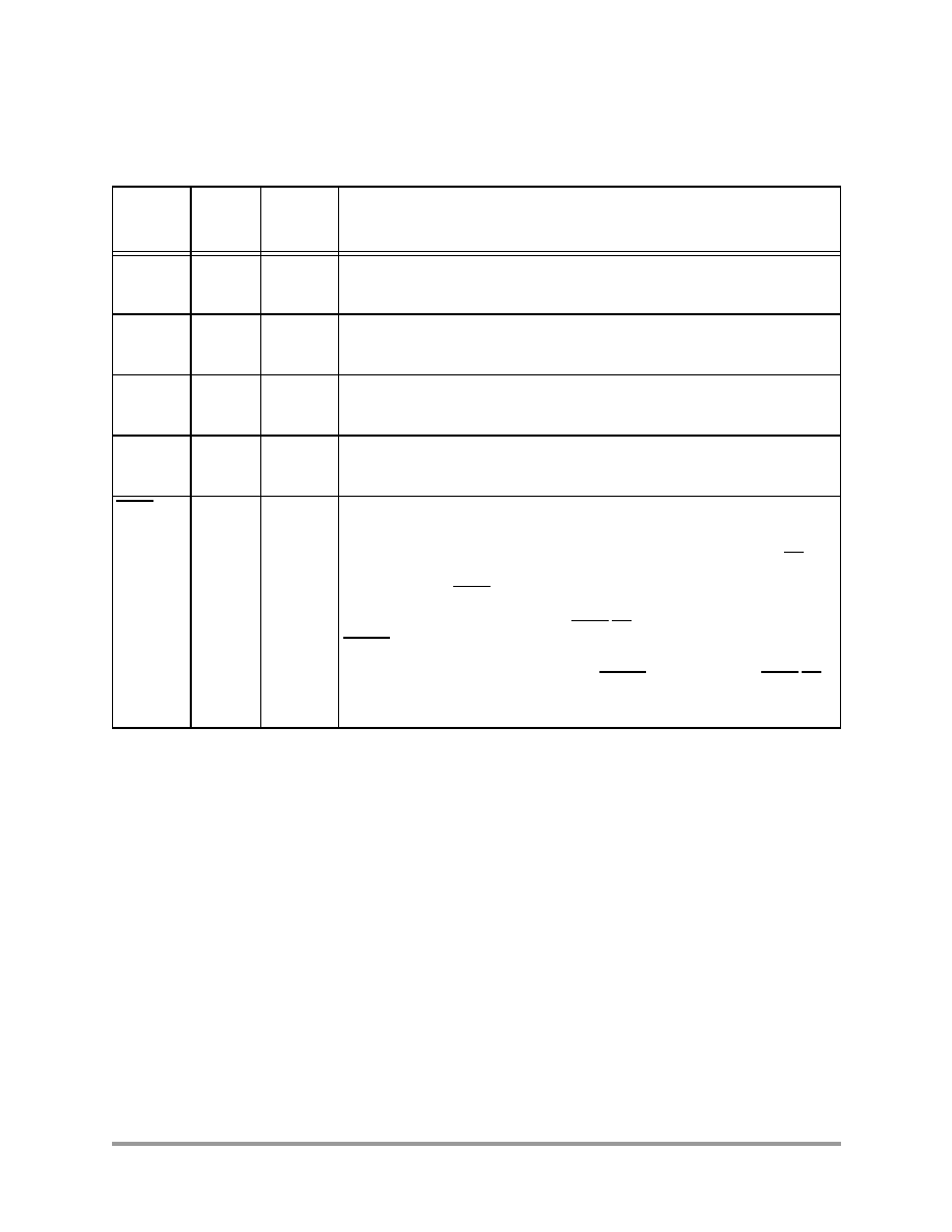
3.8 Reset, Stop, Wait, Mode Select, and Interrupt
Timing
(V
SS
= 0 V, V
DD
= 2.7≠3.6 V, T
A
= ≠40
∞
to +85
∞
C, C
L
= 50 pF)
Figure 12. External Bus Asynchronous Timing
Table 26. Reset, Stop, Wait, Mode Select, and Interrupt Timing
No.
Characteristics
70 MHz
Unit
Min
1
Max
1
60
RESET Assertion to Address, Data and Control Signals
High Impedance
4.6
14.0
ns
61
Minimum RESET Assertion Duration
2
OMR Bit 6 = 0
OMR Bit 6 = 1
524,329 + 38
T
38T
--
--
ns
ns
62
Asynchronous RESET Deassertion to First External
Address Output
3
67T + 4.5
67T + 12.3
ns
63
Synchronous Reset Setup Time from RESET Deassertion
to CLKO Low
3.8
5.6
ns
64
Synchronous Reset Delay Time from CLKO High to the
First External Access
3
66T + 2.5
66T + 7.5
ns
65
Mode and XCOLF Select Setup Time
0.3
--
ns
A0≠A15,
PS, DS
(See Note)
WR
D0≠D15
RD
Note: During Read-Modify-Write instructions and internal instructions, the address lines do not change state.
51
50
Data In
Data Out
48
46
53
40
54
41
52
55
49
43
44
42
45
47
AA1451
F
r
e
e
s
c
a
l
e
S
e
m
i
c
o
n
d
u
c
t
o
r
,
I
Freescale Semiconductor, Inc.
For More Information On This Product,
Go to: www.freescale.com
n
c
.
.
.

Reset, Stop, Wait, Mode Select, and Interrupt Timing
DSP56824 Technical Data
31
66
Mode and XCOLF Select Hold Time
0
--
ns
67
Edge-sensitive Interrupt Request Width
2T + 3.8
--
ns
68
IRQA, IRQB Assertion to External Data Memory Access
Out Valid, caused by first instruction execution in the
interrupt service routine
28 + 2.5
--
ns
69
IRQA, IRQB Assertion to General Purpose Output Valid,
caused by first instruction execution in the interrupt service
routine
31T + 3.7
--
ns
70
Synchronous setup time from IRQA, IRQB assertion to
Synchronous CLKO High
4, 5
1.9
2T
ns
71
CLKO Low to First Interrupt Vector Address Out Valid after
Synchronous recovery from Wait State
6
24T + 4.4
--
ns
72
IRQA Width Assertion to Recover from Stop State
7
2T + 3.8
--
ns
73
Delay from IRQA Assertion to Fetch of first instruction
(exiting Stop)
2
OMR Bit 6 = 0
OMR Bit 6 = 1
524,329T
22T
--
--
ns
ns
74
Duration for Level Sensitive IRQA Assertion to Cause the
Fetch of First IRQA Interrupt Instruction (exiting Stop)
2
OMR Bit 6 = 0
OMR Bit 6 = 1
524,329T
22T
--
--
ns
ns
75
Delay from Level Sensitive IRQA Assertion to First Interrupt
Vector Address Out Valid (exiting Stop)
2
OMR Bit 6 = 0
OMR Bit 6 = 1
524,336T + 2.
5
22T + 2.5
--
--
ns
ns
1.
In the formulas, T = 1/2 the clock cycle and WS = the number of wait states. For an internal frequency of
70 MHz, T = 7.14 ns.
2.
Circuit stabilization delay is required during reset when using an external clock or crystal oscillator in two
cases:
∑ After power-on reset
∑ When recovering from Stop state
3.
The instruction fetch is visible on the pins only in Mode 2 and Mode 3.
4.
Timing No. 72 is for all IRQx interrupts, while timing No. 73 is only when exiting the Wait state.
5.
Timing No. 72 triggers off T0 in the Normal state and off phi0 when exiting the Wait state.
6.
The minimum is specified for the duration of an edge-sensitive IRQA interrupt required to recover from the
Stop state. This is not the minimum required so that the IRQA interrupt is accepted.
7.
The interrupt instruction fetch is visible on the pins only in Mode 3.
Table 26. Reset, Stop, Wait, Mode Select, and Interrupt Timing (Continued)
No.
Characteristics
70 MHz
Unit
Min
1
Max
1
F
r
e
e
s
c
a
l
e
S
e
m
i
c
o
n
d
u
c
t
o
r
,
I
Freescale Semiconductor, Inc.
For More Information On This Product,
Go to: www.freescale.com
n
c
.
.
.

32
DSP56824 Technical Data
Figure 13. Asynchronous Reset Timing
Figure 14. Synchronous Reset Timing
Figure 15. Operating Mode Select Timing
Figure 16. External Interrupt Timing (Negative-Edge-Sensitive)
First Fetch
61
60
62
A0≠A15,
D0≠D15
PS, DS,
RD, WR
RESET
First Fetch
AA1452
63
A0≠A15,
PS, DS,
RD, WR
RESET
64
CLKO
AA0187
RESET
MODA,
MODB,
IRQA,
IRQB,
65
66
AA0188
XCOLF
PB15
IRQA,
IRQB
67
AA0189
F
r
e
e
s
c
a
l
e
S
e
m
i
c
o
n
d
u
c
t
o
r
,
I
Freescale Semiconductor, Inc.
For More Information On This Product,
Go to: www.freescale.com
n
c
.
.
.
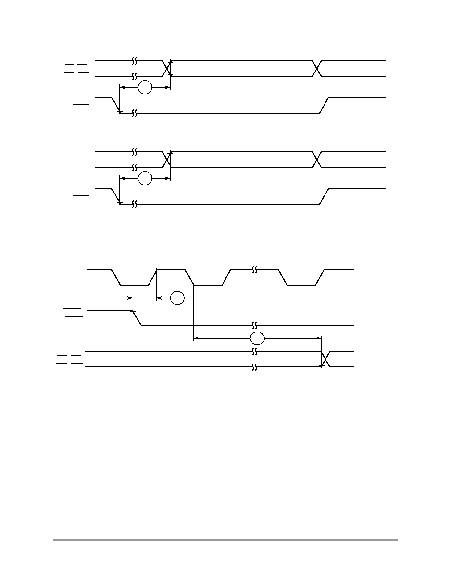
Reset, Stop, Wait, Mode Select, and Interrupt Timing
DSP56824 Technical Data
33
Figure 17. External Level-Sensitive Interrupt Timing
Figure 18. Synchronous Interrupt from Wait State Timing
68
A0≠A15,
PS
,
DS
,
RD
,
WR
IRQA
,
IRQB
First Interrupt Instruction Execution
a) First Interrupt Instruction Execution
69
General
Purpose
I/O Pin
IRQA
,
IRQB
b) General Purpose I/O
AA0190
Instruction Fetch
71
IRQA,
IRQB
AA0191
First Interrupt Vector
70
CLKO
A0≠A15,
PS, DS,
RD, WR
T0, T2
phi0
T1, T3
phi1
F
r
e
e
s
c
a
l
e
S
e
m
i
c
o
n
d
u
c
t
o
r
,
I
Freescale Semiconductor, Inc.
For More Information On This Product,
Go to: www.freescale.com
n
c
.
.
.

34
DSP56824 Technical Data
Figure 19. Recovery from Stop State Using Asynchronous Interrupt Timing
Figure 20. Recovery from Stop State Using IRQA Interrupt Service
3.9 Port B and C Pin GPIO Timing
(V
SS
= 0 V, V
DD
= 2.7≠3.6 V, T
A
= ≠40
∞
to +85
∞
C, C
L
= 50 pF)
Table 27. GPIO Timing
No.
Characteristics
Min
1
Max
1
Unit
80
CLKO high to GPIO out valid (GPIO out delay time)
2
--
10.7
ns
81
CLKO high to GPIO out not valid (GPIO out hold time)
1.5
--
ns
82
GPIO in valid to CLKO high (GPIO in set-up time)
7.8
--
ns
83
CLKO high to GPIO in not valid (GPIO in hold time)
0.5
--
ns
84
Fetch to CLKO high before GPIO change
12T ≠ 1.7
--
ns
Not IRQA Interrupt Vector
72
IRQA
AA0192
73
A0≠A15,
PS, DS,
RD, WR
First Instruction Fetch
Instruction Fetch
74
IRQA
75
A0≠A15
PS, DS,
RD, WR
First IRQA Interrupt
AA0193
F
r
e
e
s
c
a
l
e
S
e
m
i
c
o
n
d
u
c
t
o
r
,
I
Freescale Semiconductor, Inc.
For More Information On This Product,
Go to: www.freescale.com
n
c
.
.
.

Port B and C Pin GPIO Timing
DSP56824 Technical Data
35
85
Port B interrupt pulse width
4T
--
ns
86
Port B interrupt assertion to external data memory access out
valid, caused by first instruction execution in the interrupt service
routine
19T + 9.6
--
ns
87
Port B interrupt assertion to general purpose output valid, caused
by first instruction execution in the interrupt service routine
31T + 10.
8
--
ns
1.
In the formulas, T = 1/2 the clock cycle. For an internal frequency of 70 MHz, T = 7.14 ns.
2.
If a 10 kW pullup or pulldown resistor is connected to XCOLF/PB15, add 3.9 ns for timings on
XCOLF/PB15.
Figure 21. GPIO Timing
Figure 22. Port B Interrupt Timing (Negative-Edge-Sensitive)
Table 27. GPIO Timing (Continued)
No.
Characteristics
Min
1
Max
1
Unit
GPIO
(Input)
GPIO
(Output)
CLKO
(Output)
Fetch the instruction MOVE X0,X:(R0); X0 contains the new value of GPIO
and R0 contains the address of GPIO data register.
A0≠A15
AA0194
80
84
83
VALID
81
82
85
Port B
GPIO
Interrupt
(Input)
AA0195
F
r
e
e
s
c
a
l
e
S
e
m
i
c
o
n
d
u
c
t
o
r
,
I
Freescale Semiconductor, Inc.
For More Information On This Product,
Go to: www.freescale.com
n
c
.
.
.

36
DSP56824 Technical Data
3.10 Serial Peripheral Interface (SPI) Timing
(V
SS
= 0 V, V
DD
= 2.7≠3.6 V, T
A
= ≠40
∞
to +85
∞
C)
Figure 23. Port B GPIO Interrupt Timing
Table 28. SPI Timing
No.
Characteristic
70 MHz
Unit
20 pF Output Load
50 pF Output Load
Min
Max
Min
Max
90
Cycle time
Master
Slave
100
100
--
--
100
100
--
--
ns
ns
91
Enable lead time
Master
Slave
--
6.8
--
--
--
25
--
--
ns
ns
92
Enable lag time
Master
Slave
--
6.5
--
--
--
100
--
--
ns
ns
93
Clock (SCK) high time
Master
Slave
17.6
25
--
--
17.6
25
--
--
ns
ns
94
Clock (SCK) low time
Master
Slave
24.1
25
--
--
24.1
25
--
--
ns
ns
86
A0≠A15,
PS
,
DS
,
RD
,
WR
First Interrupt Instruction Execution
a) First Interrupt Instruction Execution
87
General
Purpose
I/O Pin
b) General Purpose I/O
AA0196
Port B
GPIO
Interrupt
(Input)
Port B
GPIO
Interrupt
(Input)
F
r
e
e
s
c
a
l
e
S
e
m
i
c
o
n
d
u
c
t
o
r
,
I
Freescale Semiconductor, Inc.
For More Information On This Product,
Go to: www.freescale.com
n
c
.
.
.
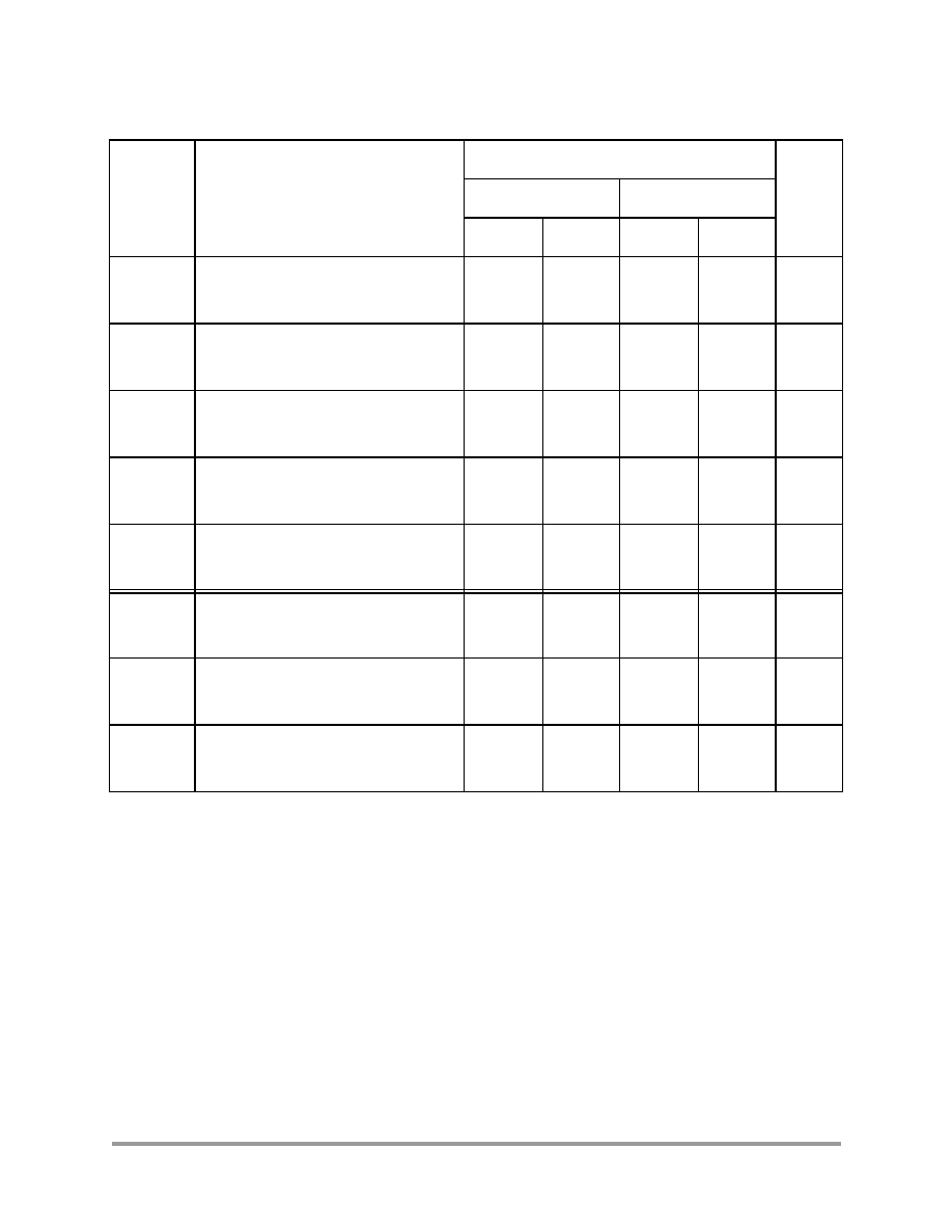
Serial Peripheral Interface (SPI) Timing
DSP56824 Technical Data
37
95
Data setup time (inputs)
Master
Slave
15.6
≠3.2
--
--
20
0
--
--
ns
ns
96
Data hold time (inputs)
Master
Slave
0
0
--
--
0
0
--
--
ns
ns
97
Access time (time to data active from
high-impedance state)
Slave 4.8
10.7
4.8
15
ns
ns
98
Disable time (hold time to high-
impedance state)
Slave 3.7
15.2
3.7
15.2
ns
ns
99
Data Valid
Master
Slave (after enable edge)
4.5
4.6
3.5
20.4
4.5
4.6
3.5
20.4
ns
ns
100
Data invalid
Master
Slave
0
0
--
--
0
0
--
--
ns
ns
101
Rise time
Master
Slave
4.1
0
5.5
4.0
4.1
0
11.5
10.0
ns
ns
102
Fall time
Master
Slave
1.5
0
4.7
4.0
2.0
2.0
9.7
9.0
ns
ns
Table 28. SPI Timing (Continued)
No.
Characteristic
70 MHz
Unit
20 pF Output Load
50 pF Output Load
Min
Max
Min
Max
F
r
e
e
s
c
a
l
e
S
e
m
i
c
o
n
d
u
c
t
o
r
,
I
Freescale Semiconductor, Inc.
For More Information On This Product,
Go to: www.freescale.com
n
c
.
.
.
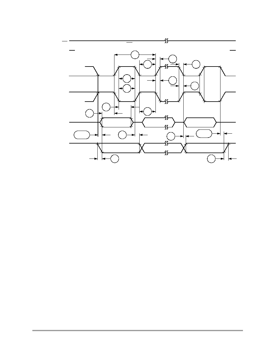
38
DSP56824 Technical Data
Figure 24. SPI Master Timing (CPH = 0)
Note: This first clock edge is generated internally, but is not seen at the SCK pin.
SCK (CPL = 0)
(Output)
SCK (CPL = 1)
(Output)
MISO
(Input)
MOSI
(Output)
See
MSB in
Note
Note
See
Bits 6≠1
LSB in
102
90
94
94
101
101
102
95
96
93
99 (ref)
100
99
100 (ref)
101
102
Master MSB out
Bits 6≠1
Master LSB out
SS
(Input)
AA0197
93
SS is held High on master
F
r
e
e
s
c
a
l
e
S
e
m
i
c
o
n
d
u
c
t
o
r
,
I
Freescale Semiconductor, Inc.
For More Information On This Product,
Go to: www.freescale.com
n
c
.
.
.

Serial Peripheral Interface (SPI) Timing
DSP56824 Technical Data
39
Figure 25. SPI Master Timing (CPH = 1)
Note: This last clock edge is generated internally, but is not seen at the SCK pin.
SCK (CPL = 0)
(Output)
SCK (CPL = 1)
(Output)
MISO
(Input)
MOSI
(Output)
See
MSB in
Note
Bits 6≠1
LSB in
101
90
94
94
102
93
99 (ref)
99
100 (ref)
101
102
Master MSB out
Bits 6 ≠ 1
Master LSB out
SS
(Input)
AA0198
93
SS is held High on master
95
See
Note
96
100
101
102
F
r
e
e
s
c
a
l
e
S
e
m
i
c
o
n
d
u
c
t
o
r
,
I
Freescale Semiconductor, Inc.
For More Information On This Product,
Go to: www.freescale.com
n
c
.
.
.

40
DSP56824 Technical Data
Figure 26. SPI Slave Timing (CPH = 0)
Note: Not defined, but normally MSB of character just received
SCK (CPL = 0)
(Input)
SCK (CPL = 1)
(Input)
MISO
(Output)
MOSI
(Input)
Slave MSB out
Bits 6≠1
90
94
94
102
93
100
MSB in
Bits 6≠1
LSB in
SS
(Input)
AA0199
93
96
101
92
91
102
Slave LSB out
See
Note
98
97
95
99
100
101
F
r
e
e
s
c
a
l
e
S
e
m
i
c
o
n
d
u
c
t
o
r
,
I
Freescale Semiconductor, Inc.
For More Information On This Product,
Go to: www.freescale.com
n
c
.
.
.

Synchronous Serial Interface (SSI) Timing
DSP56824 Technical Data
41
3.11 Synchronous Serial Interface (SSI) Timing
(V
SS
= 0 V, V
DD
= 2.7≠3.6 V, T
A
= ≠40
∞
to +85
∞
C, C
L
= 50 pF)
Figure 27. SPI Slave Timing (CPH = 1)
Table 29. SSI Timing
No.
Characteristic
70 MHz
Case
1
Unit
Min
Max
Internal Clock Operation
110
Clock cycle
2
100
--
i ck
ns
111
Clock high period
33.2
--
i ck
ns
112
Clock low period
30.6
--
i ck
ns
113
Output clock rise/fall time
--
7.5
i ck
ns
114
STCK high to STFS (bl) high
3
1.8
9.7
i ck
ns
115
SRCK high to SRFS (bl) high
3
1.3
10
i ck
ns
116
STCK high to STFS (bl) low
3
≠2.9
8
i ck
ns
Note: Not defined, but normally LSB of character previously transmitted
AA0200
K (CPL = 0)
(Input)
K (CPL = 1)
(Input)
MISO
(Output)
MOSI
(Input)
Slave MSB out
Bits 6≠1
90
94
94
93
100
MSB in
Bits 6≠1
LSB in
SS
(Input)
93
96
102
101
Slave LSB out
See
Note
98
97
91
99
102
101
92
99
95
F
r
e
e
s
c
a
l
e
S
e
m
i
c
o
n
d
u
c
t
o
r
,
I
Freescale Semiconductor, Inc.
For More Information On This Product,
Go to: www.freescale.com
n
c
.
.
.

42
DSP56824 Technical Data
117
SRCK high to SRFS (bl) low
3
≠2.7
8.7
i ck
ns
118
SRD setup time before SRCK low
9
--
i ck
ns
119
SRD hold time after SRCK low
0
--
i ck
ns
120
STCK high to STFS (wl) high
3
13.8
24.4
i ck
ns
121
SRCK high to SRFS (wl) high
3
14.5
25.9
i ck
ns
122
STCK high to STFS (wl) low
3
≠2.9
9.0
i ck
ns
123
SRCK high to SRFS (wl) low
3
≠2.2
10.6
i ck
ns
124
STCK high to STD enable from high impedance
1.5
1.7
i ck
ns
125
STCK high to STD valid
≠3.4
7.9
i ck
ns
126
STCK High to STD not valid
≠5.7
0.7
i ck
ns
127
STCK high to STD high impedance
6.8
11.3
i ck
ns
External Clock Operation
128
Clock cycle
2
100
--
x ck
ns
129
Clock high period
50
--
x ck
ns
130
Clock low period
50
--
x ck
ns
132
SRD Setup time before SRCK low
≠8.7
--
x ck
ns
133
SRD hold time after SRCK low
4
1.7
--
x ck
ns
134
STCK high to STFS (bl) high
3
0.4
100
x ck
ns
135
SRCK high to SRFS (bl) high
3
0.5
100
x ck
ns
136
STCK high to STFS (bl) low
3
0
99
x ck
ns
137
SRCK high to SRFS (bl) low
3
0
99
x ck
ns
138
STCK high to STFS (wl) high
3
0.4
100
x ck
ns
139
SRCK high to SRFS (wl) high
3
0.5
100
x ck
ns
140
STCK high to STFS (wl) low
3
0
99
x ck
ns
141
SRCK high to SRFS (wl) low
3
0
99
x ck
ns
Table 29. SSI Timing (Continued)
No.
Characteristic
70 MHz
Case
1
Unit
Min
Max
F
r
e
e
s
c
a
l
e
S
e
m
i
c
o
n
d
u
c
t
o
r
,
I
Freescale Semiconductor, Inc.
For More Information On This Product,
Go to: www.freescale.com
n
c
.
.
.

Synchronous Serial Interface (SSI) Timing
DSP56824 Technical Data
43
142
STCK high to STD enable from high impedance
7.8
19
x ck
ns
143
STCK high to STD valid
11.7
28.5
x ck
ns
144
STCK high to STD not valid
5.8
21.1
x ck
ns
145
STCK high to STD high impedance
9.2
22.9
x ck
ns
Synchronous Internal Clock Operation
(in addition to standard internal clock parameters)
146
SRD setup before STCK falling
18.4
--
i ck s
ns
147
SRD hold after STCK falling
4
0
--
i ck s
ns
Synchronous External Clock Operation
(in addition to standard external clock parameters)
148
SRD setup before STCK falling
≠4.7
--
x ck s
ns
149
SRD hold after STCK falling
4
1.7
--
x ck s
ns
1.
The following abbreviations are used to represent the various operational cases:
i ck = Internal Clock and Frame Sync
x ck = External Clock and Frame Sync
i ck s = Internal Clock, Synchronous mode (implies that only one frame sync FS is used)
x ck s = External Clock, Synchronous mode (implies that only one frame sync FS is used)
2.
All the timings for the SSI are given for a non-inverted serial clock polarity (SCKP = 0 in CRB) and a non-
inverted frame sync (FSI = 0 in CRB). If the polarity of the clock and/or the frame sync have been inverted, all
the timings remain valid by inverting the clock signal SCK and/or the frame sync FSR/FST in the tables and in
the figures.
3.
bl = bit length; wl = word length.
Table 29. SSI Timing (Continued)
No.
Characteristic
70 MHz
Case
1
Unit
Min
Max
F
r
e
e
s
c
a
l
e
S
e
m
i
c
o
n
d
u
c
t
o
r
,
I
Freescale Semiconductor, Inc.
For More Information On This Product,
Go to: www.freescale.com
n
c
.
.
.

44
DSP56824 Technical Data
Figure 28. SSI Transmitter Internal Clock Timing
Note:
SRD Input in Synchronous mode only
STCK
Output
STFS (bl)
Output
STFS (wl)
Output
STD
Output
SRD
Input
113
111
112
110
114
116
147
120
146
122
First Bit
Last Bit
First Bit
Last Bit
AA0201
127
126
124
125
F
r
e
e
s
c
a
l
e
S
e
m
i
c
o
n
d
u
c
t
o
r
,
I
Freescale Semiconductor, Inc.
For More Information On This Product,
Go to: www.freescale.com
n
c
.
.
.

Synchronous Serial Interface (SSI) Timing
DSP56824 Technical Data
45
Figure 29. SSI Transmitter External Clock Timing
Note:
SRD Input in Synchronous mode only
STCK
Input
STFS (bl)
Input
STFS (wl)
Input
STD
Output
SRD
Input
129
130
128
136
149
138
148
First Bit
Last Bit
First Bit
Last Bit
AA0202
145
144
142
143
140
134
F
r
e
e
s
c
a
l
e
S
e
m
i
c
o
n
d
u
c
t
o
r
,
I
Freescale Semiconductor, Inc.
For More Information On This Product,
Go to: www.freescale.com
n
c
.
.
.

46
DSP56824 Technical Data
Figure 30. SSI Receiver Internal Clock Timing
Figure 31. SSI Receiver External Clock Timing
SRCK
Output
SRFS (bl)
Output
RFS (wl)
Output
SRD
Input
113
111
112
110
115
117
119
121
118
123
First Bit
Last Bit
AA0203
SRCK
Input
SRFS (bl)
Input
SRFS (wl)
Input
SRD
Input
129
130
128
137
133
139
132
First Bit
Last Bit
AA0204
141
135
F
r
e
e
s
c
a
l
e
S
e
m
i
c
o
n
d
u
c
t
o
r
,
I
Freescale Semiconductor, Inc.
For More Information On This Product,
Go to: www.freescale.com
n
c
.
.
.

Timer Timing
DSP56824 Technical Data
47
3.12 Timer Timing
(V
SS
= 0 V, V
DD
= 2.7≠3.6 V, T
A
= ≠40
∞
to +85
∞
C, C
L
= 50 pF)
Table 30. Timer Timing
No.
Characteristic
70 MHz
Unit
Min
Max
150
Timer input valid to CLKO high (setup time)
11.4
--
ns
151
CLKO high to timer input not valid (hold time)
0
--
ns
152
CLKO high to timer output asserted
9.5
18.7
ns
153
CLKO high to timer output deasserted
5.1
20.7
ns
154
Timer input period
8T
--
ns
155
Timer input high/low period
4T
--
ns
Figure 32. Timer Timing
152
150
153
CLKO
(Output)
TIO01
TIO2
(Input)
TIO01
TIO2
(Output)
AA0205
TIO01
TIO2
(Input)
154
155
155
151
F
r
e
e
s
c
a
l
e
S
e
m
i
c
o
n
d
u
c
t
o
r
,
I
Freescale Semiconductor, Inc.
For More Information On This Product,
Go to: www.freescale.com
n
c
.
.
.

48
DSP56824 Technical Data
3.13 JTAG Timing
(V
SS
= 0 V, V
DD
= 2.7≠3.6 V, T
A
= ≠40
∞
to +85
∞
C, C
L
= 50 pF)
Table 31. JTAG Timing
No.
Characteristics
70 MHz
Unit
Min Max
160
TCK frequency of operation
In OnCE Debug mode (EXTAL/8)
In JTAG mode
0.0
0.0
8.75
10
MHz
MHz
161
TCK cycle time
100
--
ns
162
TCK clock pulse width
50
--
ns
164
Boundary scan input data setup time
34.5
--
ns
165
Boundary scan input data hold time
0
--
ns
166
TCK low to output data valid
--
40.6
ns
167
TCK low to output tri-state
--
43.4
ns
168
TMS, TDI data setup time
0.4
--
ns
169
TMS, TDI data hold time
1.2
--
ns
170
TCK low to TDO data valid
--
26.6
ns
171
TCK low to TDO tri-state
--
23.5
ns
172
TRST assertion time
50
--
ns
173
DE assertion time
8T
--
ns
Note:
Timing is both wait state and frequency dependent. In the formulas listed, WS = the number of wait states
and T = 1/2 the clock cycle. For 70 MHz operation, T = 7.14 ns.
Figure 33. Test Clock Input Timing Diagram
TCK
(Input)
V
M
V
IL
V
M
= V
IL
+ (V
IH
≠ V
IL
)/2
162
161
162
V
M
V
IH
AA1453
F
r
e
e
s
c
a
l
e
S
e
m
i
c
o
n
d
u
c
t
o
r
,
I
Freescale Semiconductor, Inc.
For More Information On This Product,
Go to: www.freescale.com
n
c
.
.
.

JTAG Timing
DSP56824 Technical Data
49
Figure 34. Boundary Scan (JTAG) Timing Diagram
Figure 35. Test Access Port Timing Diagram
TCK
(Input)
Data
Inputs
Data
Outputs
Data
Outputs
Data
Outputs
Input Data Valid
Output Data Valid
Output Data Valid
AA0207
164
165
166
167
166
Input Data Valid
Output Data Valid
Output Data Valid
AA0208
168
169
170
171
170
TCK
(Input)
TDI
(Input)
TDO
(Output)
TDO
(Output
)
TDO
(Output)
TMS
F
r
e
e
s
c
a
l
e
S
e
m
i
c
o
n
d
u
c
t
o
r
,
I
Freescale Semiconductor, Inc.
For More Information On This Product,
Go to: www.freescale.com
n
c
.
.
.

50
DSP56824 Technical Data
Figure 36. TRST Timing Diagram
Figure 37. OnCE--Debug Event
TRST
(Input)
172
AA0209
DE
173
AA0210
F
r
e
e
s
c
a
l
e
S
e
m
i
c
o
n
d
u
c
t
o
r
,
I
Freescale Semiconductor, Inc.
For More Information On This Product,
Go to: www.freescale.com
n
c
.
.
.

Package and Pin-Out Information
DSP56824 Technical Data
51
Part 4 Packaging
4.1 Package and Pin-Out Information
This section contains package and pin-out information for the 100-pin Thin Quad Flat Pack (TQFP)
configuration of the DSP56824.
Figure 38. Top View, DSP56824 100-pin TQFP Package
Orientation Mark
1
26
(Top View)
25
50
75
51
76
100
XTAL
EXTAL
V
DD
SXFC
V
DDPLL
V
SSPLL
PC0/MISO0
PC1/MOSI0
PC2/SCK0
PC3/SS0
PC4/MISO1
PC5/MOSI1
PC6/SCK1
V
SS
V
DD
PC7/SS1
PC8/STD
PC9/SRD
PC10/STCK
PC11/STFS
PC12/SRCK
PC13/SRFS
PC14/TIO01
PC15/TIO2
WR
V
SS
CL
KO
PB1
5/XCOLF
PB1
4
PB1
3
PB1
2
V
DD
V
SS
PB1
1
PB1
0
PB9
PB8
PB7
PB6
PB5
V
SS
V
DD
PB4
PB3
PB2
PB1
PB0
M
O
D
A
/IRQ
A
M
O
D
B
/IRQ
B
RESET
RD
A15
A14
A13
A12
A11
A10
A9
V
DD
V
SS
A8
A7
A6
A5
V
SS
V
DD
PS
DS
V
SS
V
DD
A4
A3
A2
A1
A0
TDI
TRST/DE
TCK
TMS
TDO
D15
D14
V
DD
V
SS
D13
D12
D11
D10
D9
D8
D7
D6
D5
V
SS
V
DD
D4
D3
D2
D1
D0
AA1454
F
r
e
e
s
c
a
l
e
S
e
m
i
c
o
n
d
u
c
t
o
r
,
I
Freescale Semiconductor, Inc.
For More Information On This Product,
Go to: www.freescale.com
n
c
.
.
.

52
DSP56824 Technical Data
Figure 39. Bottom View, DSP56824 TQFP Package
Orientation Mark
1
26
(Bottom View)
25
50
75
51
76
100
TDI
TRST/DE
TCK
TMS
TDO
D15
D14
V
DD
V
SS
D13
D12
D11
D10
D9
D8
D7
D6
D5
V
SS
V
DD
D4
D3
D2
D1
D0
XTAL
EXTAL
V
DD
SXFC
V
DDPLL
V
SSPLL
PC0/MISO0
PC1/MOSI0
PC2/SCK0
PC3/SS0
PC4/MISO1
PC5/
MOSI1
PC6/
SCK1
V
SS
V
DD
PC7/SS1
PC8/STD
PC9/SRD
PC10/STCK
PC11/STFS
PC12/SRCK
PC13/SRFS
PC14/TIO01
PC15/TIO2
WR
RESET
MO
D
B
/I
RQ
B
MO
D
A
/I
RQ
A
PB0
PB1
PB2
PB3
PB4
V
DD
V
SS
PB5
PB6
PB7
PB8
PB9
PB10
PB11
V
SS
V
DD
PB12
PB13
PB14
PB15
/
XCOLF
CL
KO
V
SS
A0
A1
A2
A3
A4
V
DD
V
SS
DS
PS
V
DD
V
SS
A5
A6
A7
A8
V
SS
V
DD
A9
A10
A11
A12
A13
A14
A15
RD
AA1455
F
r
e
e
s
c
a
l
e
S
e
m
i
c
o
n
d
u
c
t
o
r
,
I
Freescale Semiconductor, Inc.
For More Information On This Product,
Go to: www.freescale.com
n
c
.
.
.

Package and Pin-Out Information
DSP56824 Technical Data
53
Table 32. DSP56824 Pin Identification by Pin Number
100-pin
Package
Pin #
Signal
Name
100-pin
Package
Pin #
Signal
Name
100-pin
Package
Pin #
Signal Name
100-pin
Package
Pin #
Signal Name
1
RD
26
D0
51
RESET
76
XTAL
2
A15
27
D1
52
MODB/IRQB
77
EXTAL
3
A14
28
D2
53
MODA/IRQA
78
V
DD
4
A13
29
D3
54
PB0
79
SXFC
5
A12
30
D4
55
PB1
80
V
DDPLL
6
A11
31
V
DD
56
PB2
81
V
SSPLL
7
A10
32
V
SS
57
PB3
82
PC0/MISO0
8
A9
33
D5
58
PB4
83
PC1/MOSI0
9
V
DD
34
D6
59
V
DD
84
PC2/SCK0
10
V
SS
35
D7
60
V
SS
85
PC3/SS0
11
A8
36
D8
61
PB5
86
PC4/MISO1
12
A7
37
D9
62
PB6
87
PC5/MOSI1
13
A6
38
D10
63
PB7
88
PC6/SCK1
14
A5
39
D11
64
PB8
89
V
SS
15
V
SS
40
D12
65
PB9
90
V
DD
16
V
DD
41
D13
66
PB10
91
PC7/SS1
17
PS
42
V
SS
67
PB11
92
PC8/STD
18
DS
43
V
DD
68
V
SS
93
PC9/SRD
19
V
SS
44
D14
69
V
DD
94
PC10/STCK
20
V
DD
45
D15
70
PB12
95
PC11/STFS
21
A4
46
TDO
71
PB13
96
PC12/SRCK
22
A3
47
TMS
72
PB14
97
PC13/SRFS
23
A2
48
TCK
73
XCOLF/PB15
98
PC14/TIO01
24
A1
49
TRST/DE
74
CLKO
99
PC15/TIO2
25
A0
50
TDI
75
V
SS
100
WR
F
r
e
e
s
c
a
l
e
S
e
m
i
c
o
n
d
u
c
t
o
r
,
I
Freescale Semiconductor, Inc.
For More Information On This Product,
Go to: www.freescale.com
n
c
.
.
.

54
DSP56824 Technical Data
Table 33. DSP56824 Pin Identification by Signal Name
Signal Name
Pin #
Signal Name
Pin #
Signal Name
Pin #
Signal Name
Pin #
A0
25
D13
41
PC0
82
TCK
48
A1
24
D14
44
PC1
83
TDI
50
A2
23
D15
45
PC2
84
TD0
46
A3
22
DE
49
PC3
85
TIO01
98
A4
21
DS
18
PC4
86
TIO2
99
A5
14
EXTAL
77
PC5
87
TMS
47
A6
13
IRQA
53
PC6
88
TRST
49
A7
12
IRQB
52
PC7
91
V
DD
9
A8
11
MISO0
82
PC8
92
V
DD
16
A9
8
MISO1
86
PC9
93
V
DD
20
A10
7
MODA
53
PC10
94
V
DD
31
A11
6
MODB
52
PC11
95
V
DD
43
A12
5
MOSI0
83
PC12
96
V
DD
59
A13
4
MOSI1
87
PC13
97
V
DD
69
A14
3
PB0
54
PC14
98
V
DD
78
A15
2
PB1
55
PC15
99
V
DD
90
CLKO
74
PB2
56
PS
17
V
DDPLL
80
D0
26
PB3
57
RD
1
V
SS
10
D1
27
PB4
58
RESET
51
V
SS
15
D2
28
PB5
61
SCK0
84
V
SS
19
D3
29
PB6
62
SCK1
88
V
SS
32
D4
30
PB7
63
SRFS
97
V
SS
42
D5
33
PB8
64
SRCK
96
V
SS
60
D6
34
PB9
65
SRD
93
V
SS
68
D7
35
PB10
66
SS0
85
V
SS
75
D8
36
PB11
67
SS1
91
V
SS
89
D9
37
PB12
70
STCK
94
V
SSPLL
81
F
r
e
e
s
c
a
l
e
S
e
m
i
c
o
n
d
u
c
t
o
r
,
I
Freescale Semiconductor, Inc.
For More Information On This Product,
Go to: www.freescale.com
n
c
.
.
.

Package and Pin-Out Information
DSP56824 Technical Data
55
D10
38
PB13
71
STD
92
WR
100
D11
39
PB14
72
STFS
95
XCOLF
73
D12
40
PB15
73
SXFC
79
XTAL
76
Table 34. DSP56824 Power Supply Pins
Pin #
Power Signal
Circuits Supplied
Pin #
Power Signal
Circuits Supplied
9
V
DD
Address Bus Buffers
and Bus Control
16
V
DD
Internal Logic
20
V
DD
69
V
DD
10
V
SS
15
V
SS
19
V
SS
68
V
SS
31
V
DD
Data Bus Buffers
59
V
DD
Clock, Bus Control, Port
B, Port C , and JTAG/
OnCE Port
43
V
DD
78
V
DD
32
V
SS
90
V
DD
42
V
SS
60
V
SS
90
V
DDPLL
PLL
75
V
SS
89
V
SSPLL
89
V
SS
Table 33. DSP56824 Pin Identification by Signal Name (Continued)
Signal Name
Pin #
Signal Name
Pin #
Signal Name
Pin #
Signal Name
Pin #
F
r
e
e
s
c
a
l
e
S
e
m
i
c
o
n
d
u
c
t
o
r
,
I
Freescale Semiconductor, Inc.
For More Information On This Product,
Go to: www.freescale.com
n
c
.
.
.

56
DSP56824 Technical Data
Table 35. 100-pin Thin Quad Flat Pack (TQFP) Mechanical Information
S
NOTES:
1.
DIMENSIONING AND TOLERANCING PER
ANSI Y14.5M, 1982.
2.
CONTROLLING DIMENSION: MILLIMETER.
3.
DATUM PLANE -H- IS LOCATED AT BOTTOM
OF LEAD AND IS COINCIDENT WITH THE
LEAD WHERE THE LEAD EXITS THE PLASTIC
BODY AT THE BOTTOM OF THE PARTING
LINE.
4.
DATUMS -L-, -M- AND -N- TO BE
DETERMINED AT DATUM PLANE -H-.
5.
DIMENSIONS S AND V TO BE DETERMINED
AT SEATING PLANE -T-.
6.
DIMENSIONS A AND B DO NOT INCLUDE
MOLD PROTRUSION. ALLOWABLE
PROTRUSION IS 0.250 (0.010) PER SIDE.
DIMENSIONS A AND B DO INCLUDE MOLD
MISMATCH AND ARE DETERMINED AT
DATUM PLANE -H-.
7.
DIMENSION D DOES NOT INCLUDE DAMBAR
PROTRUSION. DAMBAR PROTRUSION
SHALL NOT CAUSE THE LEAD WIDTH TO
EXCEED 0.350 (0.014). MINIMUM SPACE
BETWEEN PROTRUSION AND ADJACENT
LEAD OR PROTRUSION 0.070 (0.003).
PLATING
U
J
D
F
ROTATED 90
∞
CLOCKWISE
SECTION AB-AB
BASE METAL
S
L-M
M
0.08 (0.003)
NS
T
C2
C1
K
Z
W
GAGE PLANE
VIEW AA
S
0.05 (0.002)
E
0.25 (0.010)
1
2XR
R1
VIEW Y
4X 25 TIPS
4X
25
100
76
75
51
26
50
1
N
0.20 (0.008)
H L-M
N
0.20 (0.008)
T L-M
-M-
-N-
3X
-L-
A
A1
S1
B1
V1
DIM MIN
MAX
MILLIMETERS
A
14.00 BSC
A1
7.00 BSC
B
14.00 BSC
B1
7.00 BSC
C
1.70
C1
0.05
0.20
C2
1.30
1.50
D
0.10
0.30
E
0.45
0.75
F
0.15
0.23
G
0.50 BSC
J
0.07
0.20
K
0.50 REF
R1
0.08
0.20
S
16.00 BSC
S1
8.00 BSC
U
0.09
0.16
V
16.00 BSC
V1
8.00 BSC
W
0.20 REF
Z
1.00 REF
0
∞
7
∞
1
0
∞
2
12
∞
Î
REF
3
4
∞
13
∞
---
---
SEATING
PLANE
VIEW AA
C
0.08 (0.003)
T
-H-
-T-
2
4X
3
4X
AB
VIEW Y
AB
C
L
-X-
X = L, M AND N
G
V
B
CASE 983-01
F
r
e
e
s
c
a
l
e
S
e
m
i
c
o
n
d
u
c
t
o
r
,
I
Freescale Semiconductor, Inc.
For More Information On This Product,
Go to: www.freescale.com
n
c
.
.
.

Ordering Drawings
DSP56824 Technical Data
57
4.2 Ordering Drawings
Complete mechanical information regarding DSP56824 packaging is available by facsimile through
Motorola's MfaxTM system. Call the following number to obtain instructions for using this system:
The automated system requests the following information:
∑
The receiving fax telephone number including area code or country code
∑
The caller's Personal Identification Number (PIN)
NOTE:
For first time callers, the system provides instructions for setting up a PIN,
which requires entry of a name and telephone number.
-- The type of information requested:
-- Instructions for using the system
-- A literature order form
-- Specific part technical information or data sheets
-- Other information described by the system messages
A total of three documents can be ordered per call.
The mechanical drawings for the 100-pin TQFP package are referenced as 983-01.
(602) 244-6609
F
r
e
e
s
c
a
l
e
S
e
m
i
c
o
n
d
u
c
t
o
r
,
I
Freescale Semiconductor, Inc.
For More Information On This Product,
Go to: www.freescale.com
n
c
.
.
.

58
DSP56824 Technical Data
Part 5 Design Considerations
5.1 Thermal Design Considerations
An estimation of the chip junction temperature, T
J
, in
∞
C can be obtained from the equation:
Equation 1:
Where:
T
A
= ambient temperature ∞C
R
JA
= package junction-to-ambient thermal resistance ∞C/W
P
D
= power dissipation in package
Historically, thermal resistance has been expressed as the sum of a junction-to-case thermal resistance and
a case-to-ambient thermal resistance:
Equation 2:
Where:
R
JA
= package junction-to-ambient thermal resistance ∞C/W
R
JC
= package junction-to-case thermal resistance ∞C/W
R
CA
= package case-to-ambient thermal resistance ∞C/W
R
JC
is device-related and cannot be influenced by the user. The user controls the thermal environment to
change the case-to-ambient thermal resistance, R
CA
. For example, the user can change the air flow around
the device, add a heat sink, change the mounting arrangement on the Printed Circuit Board (PCB), or
otherwise change the thermal dissipation capability of the area surrounding the device on the PCB. This
model is most useful for ceramic packages with heat sinks; some 90% of the heat flow is dissipated
through the case to the heat sink and out to the ambient environment. For ceramic packages, in situations
where the heat flow is split between a path to the case and an alternate path through the PCB, analysis of
the device thermal performance may need the additional modeling capability of a system level thermal
simulation tool.
The thermal performance of plastic packages is more dependent on the temperature of the PCB to which
the package is mounted. Again, if the estimations obtained from R
JA
do not satisfactorily answer whether
the thermal performance is adequate, a system level model may be appropriate.
A complicating factor is the existence of three common definitions for determining the junction-to-case
thermal resistance in plastic packages:
∑
Measure the thermal resistance from the junction to the outside surface of the package (case) closest
to the chip mounting area when that surface has a proper heat sink. This is done to minimize
temperature variation across the surface.
∑
Measure the thermal resistance from the junction to where the leads are attached to the case. This
definition is approximately equal to a junction to board thermal resistance.
T
J
T
A
P
D
R
JA
◊
(
)
+
=
R
JA
R
JC
R
CA
+
=
F
r
e
e
s
c
a
l
e
S
e
m
i
c
o
n
d
u
c
t
o
r
,
I
Freescale Semiconductor, Inc.
For More Information On This Product,
Go to: www.freescale.com
n
c
.
.
.

Thermal Design Considerations
DSP56824 Technical Data
59
∑
Use the value obtained by the equation (T
J
≠ T
T
)/P
D
where T
T
is the temperature of the package
case determined by a thermocouple.
As noted above, the junction-to-case thermal resistances quoted in this data sheet are determined using the
first definition. From a practical standpoint, that value is also suitable for determining the junction
temperature from a case thermocouple reading in forced convection environments. In natural convection,
using the junction-to-case thermal resistance to estimate junction temperature from a thermocouple reading
on the case of the package will estimate a junction temperature slightly hotter than actual. Hence, the new
thermal metric, Thermal Characterization Parameter, or
JT
, has been defined to be (T
J
≠ T
T
)/P
D
. This
value gives a better estimate of the junction temperature in natural convection when using the surface
temperature of the package. Remember that surface temperature readings of packages are subject to
significant errors caused by inadequate attachment of the sensor to the surface and to errors caused by heat
loss to the sensor. The recommended technique is to attach a 40-gauge thermocouple wire and bead to the
top center of the package with thermally conductive epoxy.
NOTE:
Table 19 on page 20 contains the package thermal values for this chip.
F
r
e
e
s
c
a
l
e
S
e
m
i
c
o
n
d
u
c
t
o
r
,
I
Freescale Semiconductor, Inc.
For More Information On This Product,
Go to: www.freescale.com
n
c
.
.
.

60
DSP56824 Technical Data
5.2 Electrical Design Considerations
WARNING:
This device contains protective circuitry to guard against damage due to
high static voltage or electrical fields. However, normal precautions are
advised to avoid application of any voltages higher than maximum rated
voltages to this high-impedance circuit. Reliability of operation is
enhanced if unused inputs are tied to an appropriate logic voltage level
(e.g., either GND or V
CC
).
Use the following list of considerations to assure correct DSP operation:
∑
Provide a low-impedance path from the board power supply to each V
DD
pin on the DSP, and from
the board ground to each V
SS
(GND) pin.
∑
The minimum bypass requirement is to place six 0.01≠0.1
µ
F capacitors positioned as close as
possible to the package supply pins, one capacitor for each of the "Circuits Supplied" groups listed
in Table 34 on page 55. The recommended bypass configuration is to place one bypass capacitor on
each of the ten V
DD
/V
SS
pairs, including V
DDPLL
/V
SSPLL.
∑
Ensure that capacitor leads and associated printed circuit traces that connect to the chip V
DD
and
V
SS
(GND) pins are less than 0.5" per capacitor lead.
∑
Use at least a four-layer Printed Circuit Board (PCB) with two inner layers for V
DD
and GND.
∑
Bypass the V
DD
and GND layers of the PCB with approximately 100
µ
F, preferably with a high-
grade capacitor such as a tantalum capacitor.
∑
Because the DSP output signals have fast rise and fall times, PCB trace lengths should be minimal.
∑
Consider all device loads as well as parasitic capacitance due to PCB traces when calculating
capacitance. This is especially critical in systems with higher capacitive loads that could create
higher transient currents in the V
DD
and GND circuits.
∑
All inputs must be terminated (i.e., not allowed to float) using CMOS levels.
∑
Take special care to minimize noise levels on the V
DDPLL
and V
SSPLL
pins.
∑
When using Wired-OR mode on the SPI or the MODx/IRQx pins, the user must provide an external
pull-up device.
∑
Designs that utilize the TRST/DE pin for JTAG port or OnCE module functionality (such as
development or debugging systems) should allow a means to assert TRST whenever RESET is
asserted, as well as a means to assert TRST independently of RESET. Designs that do not require
debugging functionality, such as consumer products, should tie these pins together.
∑
Because the Flash memory is programmed through the JTAG/OnCE port, designers should provide
an interface to this port to allow in-circuit Flash programming.
F
r
e
e
s
c
a
l
e
S
e
m
i
c
o
n
d
u
c
t
o
r
,
I
Freescale Semiconductor, Inc.
For More Information On This Product,
Go to: www.freescale.com
n
c
.
.
.

Electrical Design Considerations
DSP56824 Technical Data
61
Part 6 Ordering Information
Table 36 lists the pertinent information needed to place an order. Consult a Motorola Semiconductor sales
office or authorized distributor to determine availability and to order parts.
Table 36. DSP56824 Ordering Information
Part
Supply
Voltage
Package Type
Pin
Count
Frequency
(MHz)
Order Number
DSP56824
2.7≠3.6 V
Plastic Thin Quad Flat Pack (TQFP)
100
70
DSP56824BU70
F
r
e
e
s
c
a
l
e
S
e
m
i
c
o
n
d
u
c
t
o
r
,
I
Freescale Semiconductor, Inc.
For More Information On This Product,
Go to: www.freescale.com
n
c
.
.
.

MFAX and OnCETM are trademarks of Motorola, Inc.
This document contains information on a new product. Specifications and information herein are subject to change
without notice.
Motorola reserves the right to make changes without further notice to any products herein. Motorola makes no warranty,
representation or guarantee regarding the suitability of its products for any particular purpose, nor does Motorola assume any liability
arising out of the application or use of any product or circuit, and specifically disclaims any and all liability, including without limitation
consequential or incidental damages. "Typical" parameters which may be provided in Motorola data sheets and/or specifications can
and do vary in different applications and actual performance may vary over time. All operating parameters, including "Typicals" must
be validated for each customer application by customer's technical experts. Motorola does not convey any license under its patent
rights nor the rights of others. Motorola products are not designed, intended, or authorized for use as components in systems
intended for surgical implant into the body, or other applications intended to support life, or for any other application in which the
failure of the Motorola product could create a situation where personal injury or death may occur. Should Buyer purchase or use
Motorola products for any such unintended or unauthorized application, Buyer shall indemnify and hold Motorola and its officers,
employees, subsidiaries, affiliates, and distributors harmless against all claims, costs, damages, and expenses, and reasonable
attorney fees arising out of, directly or indirectly, any claim of personal injury or death associated with such unintended or
unauthorized use, even if such claim alleges that Motorola was negligent regarding the design or manufacture of the part.
Motorola and
are registered trademarks of Motorola, Inc. Motorola, Inc. is an Equal Opportunity/Affirmative Action Employer.
All other tradenames, trademarks, and registered trademarks are the property of their respective owners.
How to reach us:
USA/EUROPE/Locations Not Listed: Motorola Literature Distribution; P.O. Box 5405, Denver, Colorado, 80217
1-303-675-2140 or 1-800-441-2447
JAPAN: Motorola Japan, Ltd.; SPS, Technical Information Center, 3-20-1, Minami-Azabu, Minato-ku,
Tokyo 106-8573 Japan. 81-3-3440-3569
ASIA/PACIFIC: Motorola Semiconductors H.K. Ltd., Silicon Harbour Centre, 2 Dai King Street,
Tai Po Industrial Estate, 2 Tai Po, N.T., Hong Kong. 852-26668334
Customer Focus Center: 1-800-521-6274
MfaxTM: RMFAX0@email.sps.mot.com
≠TOUCHTONE 1-602-244-6609
≠US & Canada ONLY 1-800-774-184
≠http://sps.motorola.com/mfax/
HOME PAGE: http://motorola.com/sps
Motorola DSP Products Home Page: http://www.motorola-dsp.com
DSP56824/D
F
r
e
e
s
c
a
l
e
S
e
m
i
c
o
n
d
u
c
t
o
r
,
I
Freescale Semiconductor, Inc.
For More Information On This Product,
Go to: www.freescale.com
n
c
.
.
.