©
Motorola, Inc., 2000
Motorola Semiconductor Technical Data
by HC908JL3AD/D
Order this document
Addendum to
MC68HC908JL3
Technical Data
This addendum provides additional information to:
MC68HC908JL3 Technical Data
(Motorola document number MC68HC908JL3/H
Rev. 1.0)
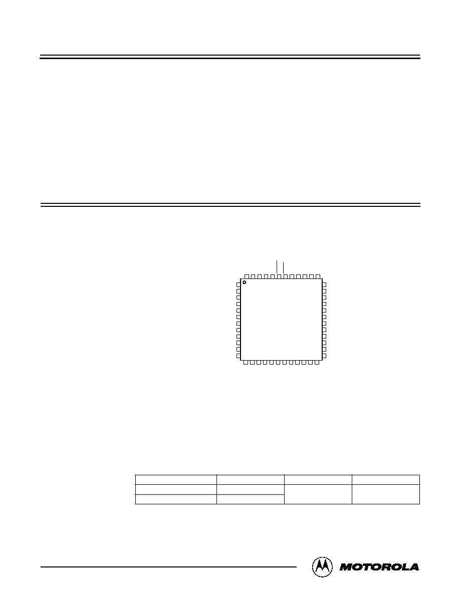
The following provides information on the 48-pin LQFP package for the
MC68HC908JL3 and MC68HRC908JL3 devices.
48-Pin LQFP
Pin Assignment
Figure 1. 48-Pin Pin Assignment
Analog Power
Supply and
Ground Pins
(V
DDA and
V
SSA
)
V
DDA
is the power supply pin for the analog circuits of the MCU. It should be decoupled
as per the V
DD
digital supply pin.
V
SSA
is the power supply ground pin for the analog circuits of the MCU. It should be
decoupled as per the V
SS
digital ground pin.
Order Numbers
RST
48
47
46
45
44
43
42
41
40
39
1
2
3
4
5
6
7
8
9
10
14
15
16
17
18
19
20
21
22
36
32
31
30
29
28
27
26
13
NC
PTA3
PTB7
NC
NC
OSC1
OSC2/PTA6
PTA1
VDDA
VDD
PTA2
PTD7
PTB6
NC
NC
PTB5
PTD6
PTB2
PTB3
PTD0
NC
PTB4
NC
NC
NC
NC
PTD3
NC
PTD1
PTB0
PTA4
PTD2
PTB1
NC
12
NC
25
NC
11
24
NC
23
35
34
33
IRQ1
PTA0
VSS
VSSA
NC
NC
PTD5
PTD4
PTA5
NC
37
38
NC: No connection
MC order number Oscillator type FLASH memory Package
MC68HC908JL3CFA Crystal oscillator
4096 Bytes 48-pin package
MC68HRC908JL3CFA RC oscillator
Notes:
C = ≠40
∞
C to +85
∞
C
FA = Plastic Low Quad Flat Pack (LQFP)

Motorola reserves the right to make changes without further notice to any products herein. Motorola makes no warranty, representation or guarantee regarding the suitability of its
products for any particular purpose, nor does Motorola assume any liability arising out of the application or use of any product or circuit, and specifically disclaims any and all liability,
including without limitation consequential or incidental damages. "Typical" parameters which may be provided in Motorola data sheets and/or specifications can and do vary in different
applications and actual performance may vary over time. All operating parameters, including "Typicals" must be validated for each customer application by customer's technical experts.
Motorola does not convey any license under its patent rights nor the rights of others. Motorola products are not designed, intended, or authorized for use as components in systems
intended for surgical implant into the body, or other applications intended to support or sustain life, or for any other application in which the failure of the Motorola product could create a
situation where personal injury or death may occur. Should Buyer purchase or use Motorola products for any such unintended or unauthorized application, Buyer shall indemnify and
hold Motorola and its officers, employees, subsidiaries, affiliates, and distributors harmless against all claims, costs, damages, and expenses, and reasonable attorney fees arising out
of, directly or indirectly, any claim of personal injury or death associated with such unintended or unauthorized use, even if such claim alleges that Motorola was negligent regarding the
design or manufacture of the part. Motorola and
are registered trademarks of Motorola, Inc. Motorola, Inc. is an Equal Opportunity/Affirmative Action Employer.
How to reach us:
USA/EUROPE/Locations Not Listed:
Motorola Literature Distribution; P.O. Box 5405, Denver, Colorado 80217. 1-303-675-2140 or 1-800-441-2447
JAPAN:
Motorola Japan Ltd.; SPS, Technical Information Center, 3-20-1, Minami-Azabu, Minato-ku, Tokyo 106-8573 Japan. 81-3-3440-3569
ASIA/PACIFIC:
Motorola Semiconductors H.K. Ltd.; Silicon Harbour Center, 2 Dai King Street, Tai Po Industrial Estate, Tai Po, N.T., Hong Kong. 852-26668334
Technical Information Center: 1-800-521-6274
HOME PAGE:
http://www.motorola.com/semiconductors/
© Motorola, Inc., 2000
Mechanical
Specification
Figure 2. 48-Pin Plastic Low Quad Flat Pack (LQFP) (Case No. 932-02)
A
A1
Z
0.200 AB T≠U
4X
Z
0.200 AC T≠U
4X
B
B1
1
12
13
24
25
36
37
48
S1
S
V
V1
P
AE
AE
T, U, Z
DETAIL Y
DETAIL Y
BASE METAL
N
J
F
D
T≠U
M
0.080
Z
AC
SECTION AE≠AE
AD
G
0.080 AC
M
∞
TOP & BOTTOM
L
∞
W
K
AA
E
C
H
0.250
R
9
DETAIL AD
NOTES:
1. DIMENSIONING AND TOLERANCING PER ASME
Y14.5M, 1994.
2. CONTROLLING DIMENSION: MILLIMETER.
3. DATUM PLANE AB IS LOCATED AT BOTTOM OF
LEAD AND IS COINCIDENT WITH THE LEAD
WHERE THE LEAD EXITS THE PLASTIC BODY AT
THE BOTTOM OF THE PARTING LINE.
4. DATUMS T, U, AND Z TO BE DETERMINED AT
DATUM PLANE AB.
5. DIMENSIONS S AND V TO BE DETERMINED AT
SEATING PLANE AC.
6. DIMENSIONS A AND B DO NOT INCLUDE MOLD
PROTRUSION. ALLOWABLE PROTRUSION IS
0.250 PER SIDE. DIMENSIONS A AND B DO
INCLUDE MOLD MISMATCH AND ARE
DETERMINED AT DATUM PLANE AB.
7. DIMENSION D DOES NOT INCLUDE DAMBAR
PROTRUSION. DAMBAR PROTRUSION SHALL
NOT CAUSE THE D DIMENSION TO EXCEED
0.350.
8. MINIMUM SOLDER PLATE THICKNESS SHALL BE
0.0076.
9. EXACT SHAPE OF EACH CORNER IS OPTIONAL.
T
U
Z
AB
AC
GAUGE PLANE
DIM
A
MIN
MAX
7.000 BSC
MILLIMETERS
A1
3.500 BSC
B
7.000 BSC
B1
3.500 BSC
C
1.400
1.600
D
0.170
0.270
E
1.350
1.450
F
0.170
0.230
G
0.500 BSC
H
0.050
0.150
J
0.090
0.200
K
0.500
0.700
M
12
∞
REF
N
0.090
0.160
P
0.250 BSC
L
1
∞
5
∞
R
0.150
0.250
S
9.000 BSC
S1
4.500 BSC
V
9.000 BSC
V1
4.500 BSC
W
0.200 REF
AA
1.000 REF