MOTOROLA
SEMICONDUCTOR
TECHNICAL DATA
Motorola TVS/Zener Device Data
4-1
500 Watt Peak Power Data Sheet
Devices listed in bold, italic are Motorola preferred devices.
Zener Transient Voltage Suppressors
Unidirectional and Bidirectional
The SA5.0A series is designed to protect voltage sensitive components from high volt-
age, high energy transients. They have excellent clamping capability, high surge capability,
low zener impedance and fast response time. The SA5.0A series is supplied in Motorola's
exclusive, cost-effective, highly reliable Surmetic axial leaded package and is ideally-suited
for use in communication systems, numerical controls, process controls, medical equip-
ment, business machines, power supplies and many other industrial/consumer applications.
Specification Features:
∑
Stand-off Zener Voltage Range -- 5 to 170 V
∑
Peak Power -- 500 Watts @ 1 ms
∑
Maximum Clamp Voltage @ Peak Pulse Current
∑
Low Leakage < 1
µ
A Above 8.5 Volts
∑
Maximum Temperature Coefficient Specified
∑
Response Time is Typically Less than 1 ns
Mechanical Characteristics:
CASE: Void-free, transfer-molded, thermosetting plastic
FINISH: All external surfaces are corrosion resistant and leads are readily solderable
POLARITY: Cathode indicated by polarity band. When operated in zener mode, will be
positive with respect to anode
MOUNTING POSITION: Any
WAFER FAB LOCATION: Phoenix, Arizona
ASSEMBLY/TEST LOCATION: Guadalajara, Mexico
MAXIMUM RATINGS
Rating
Symbol
Value
Unit
Peak Power Dissipation (1)
@ TL
25
∞
C
PPK
500
Watts
Steady State Power Dissipation
@ TL
75
∞
C, Lead Length = 3/8
Derated above TL = 75
∞
C
PD
3
30
Watts
mW/
∞
C
Forward Surge Current (2)
@ TA = 25
∞
C
IFSM
70
Amps
Operating and Storage Temperature Range
TJ, Tstg
≠ 55 to +175
∞
C
Lead Temperature not less than 1/16
from the case for 10 seconds: 230
∞
C
NOTES: 1. Nonrepetitive current pulse per Figure 4 and derated above TA = 25
∞
C per Figure 2.
NOTES:
2. 1/2 sine wave (or equivalent square wave), PW = 8.3 ms, duty cycle = 4 pulses per minute maximum.
SA5.0A
through
SA170A
MOSORB
ZENER OVERVOLTAGE
TRANSIENT
SUPPRESSORS
5≠170 VOLT
500 WATT PEAK POWER
3 WATT STEADY STATE
CASE 59-04
PLASTIC

SA5.0A through SA170A
Motorola TVS/Zener Device Data
4-2
500 Watt Peak Power Data Sheet
ELECTRICAL CHARACTERISTICS
(TA = 25
∞
C unless otherwise noted) VF = 3.5 V Max, IF* = 35 A (except bidirectional devices).
Breakdown Voltage
Working Peak
Reverse
Voltage
VRWM**
(Volts)
Maximum
Reverse
Leakage
@ VRWM
IR (
µ
A)
Maximum
Reverse
Surge
Current IRSM
{
(Amps)
Maximum
Reverse Voltage
@ IRSM
(Clamping Voltage)
VRSM (Volts)
Maximum
Voltage
Temperature
Variation
of VBR mV/
∞
C
{{
VBR
{{
(Volts)
@ IT
(mA)
Reverse
Voltage
VRWM**
(Volts)
Reverse
Leakage
@ VRWM
IR (
µ
A)
Reverse
Surge
Current IRSM
{
(Amps)
Reverse Voltage
@ IRSM
(Clamping Voltage)
VRSM (Volts)
Voltage
Temperature
Variation
of VBR mV/
∞
C
Device
Min
Max
@ IT
(mA)
VRWM**
(Volts)
@ VRWM
IR (
µ
A)
Current IRSM
{
(Amps)
(Clamping Voltage)
VRSM (Volts)
Variation
of VBR mV/
∞
C
SA5.0A
6.4
7
10
5
600
54.3
9.2
5
SA6.0A
6.67
7.37
10
6
600
48.5
10.3
5
SA6.5A
7.22
7.98
10
6.5
400
44.7
11.2
5
SA7.0A
7.78
8.6
10
7
150
41.7
12
6
SA7.5A
8.33
9.21
1
7.5
50
38.8
12.9
7
SA8.0A
8.89
9.83
1
8
25
36.7
13.6
7
SA8.5A
9.44
10.4
1
8.5
5
34.7
14.4
8
SA9.0A
10
11.1
1
9
1
32.5
15.4
9
SA10A
11.1
12.3
1
10
1
29.4
17
10
SA11A
12.2
13.5
1
11
1
27.4
18.2
11
SA12A
13.3
14.7
1
12
1
25.1
19.9
12
SA13A
14.4
15.9
1
13
1
23.2
21.5
13
SA14A
15.6
17.2
1
14
1
21.5
23.2
14
SA15A
16.7
18.5
1
15
1
20.6
24.4
16
SA16A
17.8
19.7
1
16
1
19.2
26
17
SA17A
18.9
20.9
1
17
1
18.1
27.6
19
SA18A
20
22.1
1
18
1
17.2
29.2
20
SA20A
22.2
24.5
1
20
1
15.4
32.4
23
SA22A
24.4
26.9
1
22
1
14.1
35.5
25
SA24A
26.7
29.5
1
24
1
12.8
38.9
28
SA26A
28.9
31.9
1
26
1
11.9
42.1
30
SA28A
31.1
34.4
1
28
1
11
45.4
31
SA30A
33.3
36.8
1
30
1
10.3
48.4
36
SA33A
36.7
40.6
1
33
1
9.4
53.3
39
SA36A
40
44.2
1
36
1
8.6
58.1
41
SA40A
44.4
49.1
1
40
1
7.8
64.5
46
SA43A
47.8
52.8
1
43
1
7.2
69.4
50
SA45A
50
55.3
1
45
1
6.9
72.7
52
SA48A
53.3
58.9
1
48
1
6.5
77.4
56
SA51A
56.7
62.7
1
51
1
6.1
82.4
61
SA54A
60
66.3
1
54
1
5.7
87.1
65
SA58A
64.4
71.2
1
58
1
5.3
93.6
70
SA60A
66.7
73.7
1
60
1
5.2
96.8
71
SA64A
71.1
78.6
1
64
1
4.9
103
76
SA70A
77.8
86
1
70
1
4.4
113
85
SA75A
83.3
92.1
1
75
1
4.1
121
91
SA78A
86.7
95.8
1
78
1
4
126
95
SA85A
94.4
104
1
85
1
3.6
137
103
SA90A
100
111
1
90
1
3.4
146
110
SA100A
111
123
1
100
1
3.1
162
123
SA110A
122
135
1
110
1
2.8
177
133
SA120A
133
147
1
120
1
2.5
193
146
SA130A
144
159
1
130
1
2.4
209
158
SA150A
167
185
1
150
1
2.1
243
184
SA160A
178
197
1
160
1
1.9
259
196
SA170A
189
209
1
170
1
1.8
275
208
*
* 1/2 sine wave (or equivalent square wave), PW = 8.3 ms, duty cycle = 4 pulses per minute maximum.
(continued)
** MOSORB transient suppressors are normally selected according to the maximum reverse stand-off voltage (VRWM), which should be equal to or greater than the dc or continuous peak
***
operating voltage level.
{
{
Surge current waveform per Figure 4 and derate per Figure 2.
{{
VBR measured at pulse test current IT at an ambient temperature of 25
∞
C.
FOR BIDIRECTIONAL APPLICATIONS
Preferred Bidirectional Devices --
USE CA SUFFIX for SA6.0CA through SA170CA
SA6.5CA
SA13CA
SA18CA
Electrical characteristics apply in both directions.
SA12CA
SA15CA
SA24CA
SA5.0A through SA170A
Motorola TVS/Zener Device Data
4-3
500 Watt Peak Power Data Sheet
Devices listed in bold, italic are Motorola preferred devices.
100
10
1
0.1
0.1
µ
s
1
µ
s
10
µ
s
100
µ
s
1 ms
10 ms
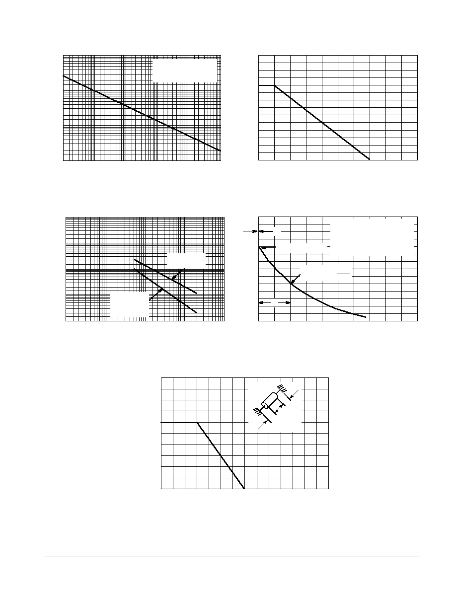
P
P
, PEAK POWER (kW)
tp, PULSE WIDTH
Figure 1. Pulse Rating Curve
NONREPETITIVE PULSE
WAVEFORM SHOWN IN
FIGURE 4
100
80
60
40
20
0
0
25
50
75
100
125
150
175
200
PEAK PULSE DERA
TING IN % OF
PEAK POWER OR CURRENT
@
T A
= 25
C
∞
TA, AMBIENT TEMPERATURE (
∞
C)
Figure 2. Pulse Derating Curve
10,000
1000
100
10
0.1
1
10
100
1000
C, CAP
ACIT
ANCE (pF)
VBR, BREAKDOWN VOLTAGE (VOLTS)
MEASURED @
ZERO BIAS
Figure 3. Capacitance versus Breakdown Voltage
100
50
0
0
1
2
3
4
t, TIME (ms)
V
ALUE (%)
PULSE WIDTH (tp) IS DEFINED
AS THAT POINT WHERE THE
PEAK CURRENT DECAYS TO 50%
OF IRSM.
tr
10
µ
s
PEAK VALUE -- IRSM
HALF VALUE ≠
IRSM
2
Figure 4. Pulse Waveform
5
4
3
2
1
0
0
25
50
75
100 125 150 175 200
P
D
, STEADY
ST
A
TE POWER DISSIP
A
TION (W
A
TTS)
TL, LEAD TEMPERATURE (
∞
C)
3/8
3/8
Figure 5. Steady State Power Derating
tr
MEASURED @
STAND-OFF
VOLTAGE (VR)
tP