1
1
!
Note
∑ Please read rating and
!
CAUTION (for storage, operating, rating, soldering, mounting and handling) in this catalog to prevent smoking and/or burning, etc.
∑ This catalog has only typical specifications because there is no space for detailed specifications. Therefore, please approve our product specifications or transact the approval sheet for product specifications before ordering.
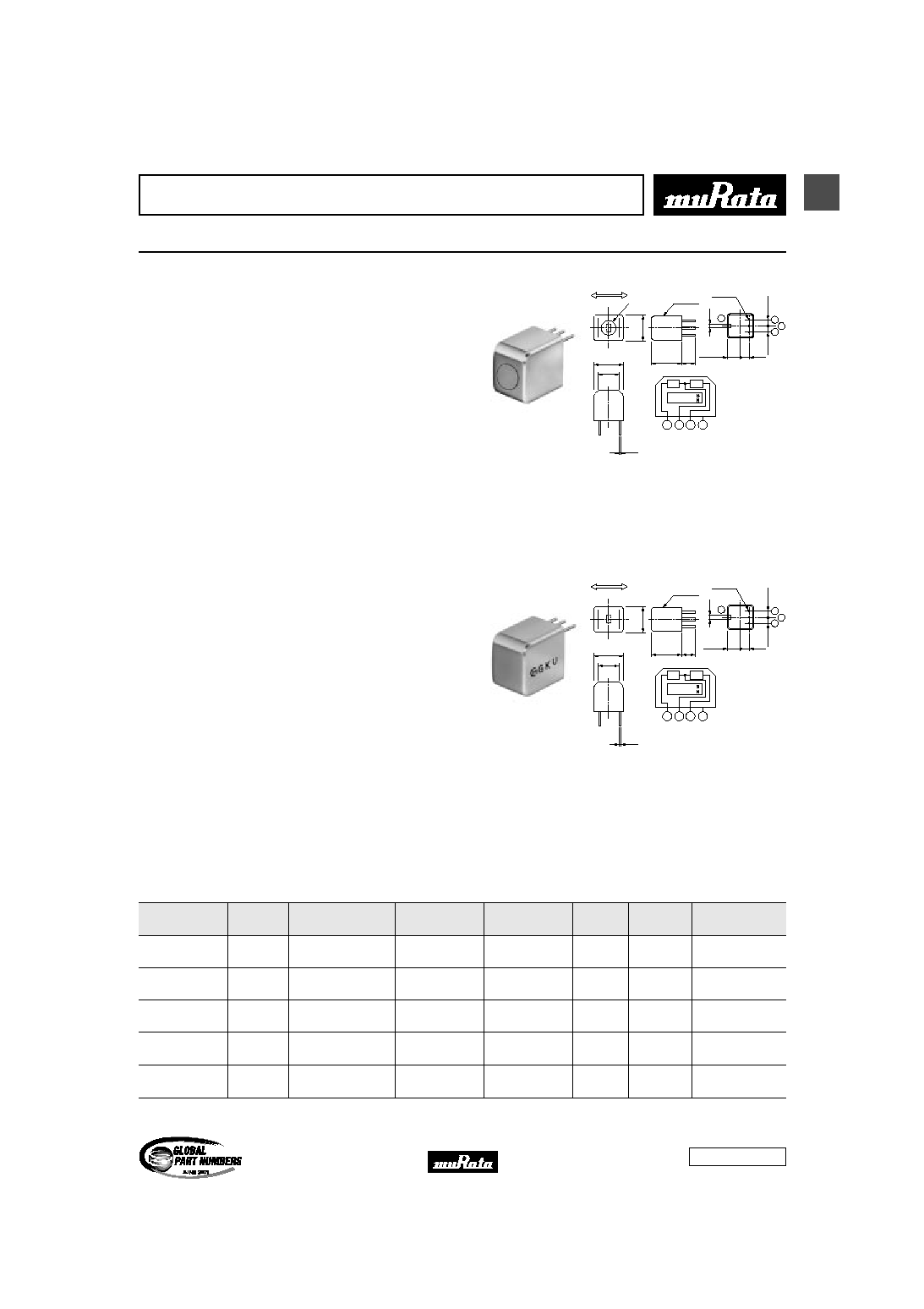
Magnetic Pattern Recognition Sensors
Standard Compact Type
s Features (BS05C Series)
1. High sensitivity and excellent gap characteristics.
2. Output voltage is independent of scanning speed.
3. Compact size and light weight make them ideal for
downsizing.
4. Longer product life is given to BS05C series with a
specially hard metal cover.
5. BS05C1HGCA has superior noise immunity against
induced noise originated from motors and
transformers.
s Applications
1. Bank note validator
2. Magnetic ink document reader
3. Magnetic card reader
4. Magnetic gear detector
4.75
±
0.2
12.5
±
0.2
2
1
3
2.5
±
0.2
2.5
±
0.2
0.8
6
±
2
8.8
±
0.2
11.1
±
0.2
8.1
±
0.2
0.2
2
1
3
4
Metal cap
Marking
Sensing direction
3≠¯0.6
Magnet
Vin Vout GND F. G
F. G : Frame GND
4
3.4
±
0.2
MR1
MR2
(in mm)
BS05C Series
s Features (BS05N Series)
1. High sensitivity and excellent gap characteristics.
2. Output voltage is independent of scanning speed.
3. Compact size and light weight make them ideal for
downsizing.
4. Low cost is achieved by BS05N1 series due to its
simple structure.
5. BS05N1HGAA has superior noise immunity against
induced noise originated from motors and
transformers.
6. BS05N1NFAA can decrease the influences when a
detection body has a location deviation because
detection width is wide with 6 mm.
s Applications
1. Bank note validator
2. Magnetic ink document reader
3. Magnetic card reader
4. Magnetic gear detector
5.3
±
0.2
12.5
±
0.2
2
1
3
2.5
±
0.2
2.5
±
0.2
0.8
6
±
2
8.8
±
0.2
11.15
±
0.2
8.1
±
0.2
0.2
2
1
3
4
Marking
Sensing direction
3≠¯0.6
Magnet
Vin Vout GND F. G
F. G : Frame GND
4
3.4
±
0.2
MR1
MR2
(in mm)
BS05N Series
Part Number
Supply
Voltage
(V)
Total
Resistance
(k ohm)
Output
Voltage
(mVrms)
Test Method
Detection
Width
(mm)
Resolution
(mm)
Operating
Temperature Range
(
∞
C)
BS05C1HFAA
5
0.5 to 6
400 min.
Test Method A
3
0.75
-20 to 60
BS05C1HGCA
5
0.5 to 6
235 to 405
Test Method A
3
0.75
-20 to 60
BS05N1HFAA
5
0.5 to 6
400 min.
Test Method A
3
0.75
-20 to 60
BS05N1HGAA
5
0.5 to 6
235 to 405
Test Method A
3
0.75
-20 to 60
BS05N1NFAA
5
0.6 to 6
330 min.
Test Method B
6
0.87
-20 to 60
Please read rating and
!
CAUTION (for storage, operating, rating, soldering, mounting and handling) in this PDF catalog to prevent smoking and/or burning, etc.
This catalog has only typical specifications. Therefore, you are requested to approve our product specifications or to transact the approval sheet for product specificaions before ordering.
!
Note
S31E3.pdf 03.4.4
Cat.No.S31E-3
2
1
!
Note
∑ Please read rating and
!
CAUTION (for storage, operating, rating, soldering, mounting and handling) in this catalog to prevent smoking and/or burning, etc.
∑ This catalog has only typical specifications because there is no space for detailed specifications. Therefore, please approve our product specifications or transact the approval sheet for product specifications before ordering.
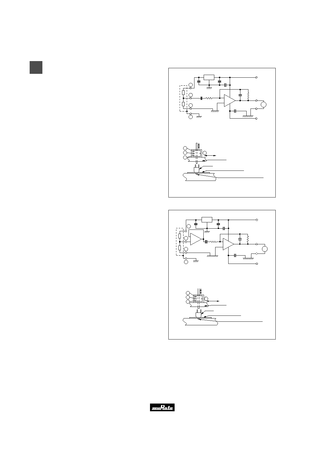
s Test Method A
1
2
3
4
2
1
3
4
10
µ
F
47
µ
F
+15V
±
5%
7805
+
-
-
+
+
-
10
µ
F
1k
0.1
µ
F
DUT
0.1
µ
F
22pF
1.5M
OUTPUT
GND
-15V
±
5%
-
+
GAIN=1,100
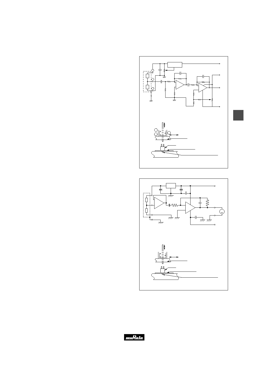
Fig. 1 Amplifier for Output Voltage Measurement
Fig. 2 Test Fixture for Output Voltage Measurement
100mArms 60Hz
DUT
Guide Rail
DUT
Mylar Film 25mm thick
Acrylic Board
Copper Wire #2UEW 0.1mm dia.
V
~
1. Amplifier's gain is set to 1,100 at the frequency of 60 Hz.
Fig. 1 shows the detail of amplifier.
2. DUT is set in the test fixture as shown in Fig. 2.
3. AC current of 100mArms is applied to the copper wire.
4. Amplifier's output voltage is read with DMM while DUT is
slowly moved along the guide rail.
s Test Method B
10
µ
F
V
10
µ
F
+15V
±
5%
1k
DUT
0.1
µ
F
22pF
1.5M
GND
-15V
±
5%
-
+
GAIN=1,100
Fig. 1 Amplifier for Output Voltage Measurement
47
µ
F
0.1
µ
F
OUTPUT
2
1
3
4
-
+
+
+
-
+
-
-
1
3
4
100mArms 60Hz
DUT
Guide Rail
Fig. 2 Test Fixture for Output Voltage Measurement
DUT
Mylar Film 25mm thick
Acrylic Board
Copper Wire #2UEW 0.1mm dia.
2
7805
~
1. Amplifier's gain is set to 1,100 at the frequency of 60 Hz.
Fig. 1 shows the detail of amplifier.
2. DUT is set in the test fixture as shown in Fig. 2.
3. AC current of 100mArms is applied to the copper wire.
4. Amplifier's output voltage is read with DMM while DUT is
slowly moved along the guide rail.
Please read rating and
!
CAUTION (for storage, operating, rating, soldering, mounting and handling) in this PDF catalog to prevent smoking and/or burning, etc.
This catalog has only typical specifications. Therefore, you are requested to approve our product specifications or to transact the approval sheet for product specificaions before ordering.
!
Note
S31E3.pdf 03.4.4
3
2
!
Note
∑ Please read rating and
!
CAUTION (for storage, operating, rating, soldering, mounting and handling) in this catalog to prevent smoking and/or burning, etc.
∑ This catalog has only typical specifications because there is no space for detailed specifications. Therefore, please approve our product specifications or transact the approval sheet for product specifications before ordering.
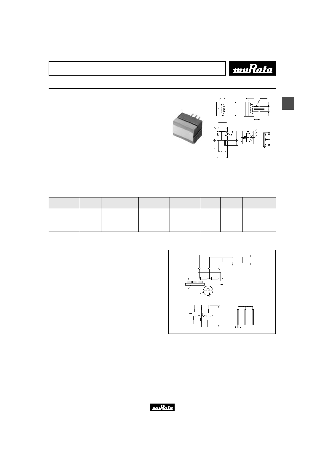
Magnetic Pattern Recognition Sensors
Wide Sensing Element Type
s Features (BS05W Series)
1. Wide MR element covering extensive area allows
increased tolerance for scanning and can accept a
variety of bank notes.
2. Long product life achieved by an extremely hard
metal cover is ideal for use in high speed ATM
and bank note counters.
3. High sensitivity and excellent gap characteristics.
4. Output voltage is independent of scanning speed.
5. BS05W1KFAB is ideal for use in high-speed process
machines such as ATM and bank note counters because
an extremely hard metal cover is used.
s Applications
1. Bank note validator
2. Magnetic ink document reader
GND
Vin
Vout
Vout
Vin
GND
F∑G
F∑G
5
.
2
1
1
±
2
5.6
Marking
(10.8)
4 2.5
11
±
0.2
1
0
.
1
±
0
.
5
6
±
2
1
5
∞
1
5
±
0
.
2
6
±
2
2
.
5
2
.
5
4-¯0.6
Sensing direction
Metal Cover
F. G : Frame GND
General torerance :
±
0.3
Metal Cover
(in mm)
MR1
MR2
BS05W Series
Part Number
Supply
Voltage
(V)
Total
Resistance
(k ohm)
Output
Voltage
(mVp-p)
Test Method
Detection
Width
(mm)
Resolution
(mm)
Operating
Temperature Range
(
∞
C)
BS05W1KFAA
5
1 to 15
0.3 to 0.8
Test Method C
10
0.75
-20 to 60
BS05W1KFAB
5
1 to 15
0.3 to 0.8
Test Method C
10
0.75
-20 to 60
s Test Method C
1. Output voltage is measured by using the magnetic pattern
card. The magnetic pattern card has the same magentic
density of 1000 letters on 1000 yen bank notes.
2. Drive the magnetic pattern card and record output voltage
Vp-p with X-Y recorder.
X-Y Recorder
DC Volage
supply
DUT
Driving speed : 2mm/s
Pressure about 98mN
Vin
Vout
GND
X axis : 2mm/s
Y axis : 0.1mV/cm
5Vdc
±
0.1V
(Input filter : ON)
Magnetic ink
Card
Rubber roller
<Output voltage Vp-p>
<Magnetic pattern>
P
P
P=15mm
1mm
V
p
-
p
Please read rating and
!
CAUTION (for storage, operating, rating, soldering, mounting and handling) in this PDF catalog to prevent smoking and/or burning, etc.
This catalog has only typical specifications. Therefore, you are requested to approve our product specifications or to transact the approval sheet for product specificaions before ordering.
!
Note
S31E3.pdf 03.4.4
4
3
!
Note
∑ Please read rating and
!
CAUTION (for storage, operating, rating, soldering, mounting and handling) in this catalog to prevent smoking and/or burning, etc.
∑ This catalog has only typical specifications because there is no space for detailed specifications. Therefore, please approve our product specifications or transact the approval sheet for product specifications before ordering.
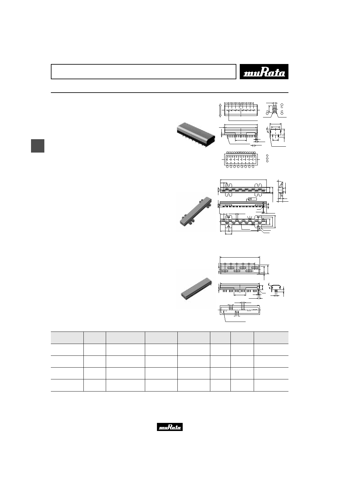
Magnetic Pattern Recognition Sensors
Multi-channel Type
s Features
1. High sensitivity and excellent gap characteristics.
2. Output voltage is independent of scanning speed.
3. Compact size and light weight make them ideal for
downsizing.
4. Simple and quick mounting is possible due to one
single holder for multiple MR elements.
5. BS05M1KFCA, BS05M1KGCA have detection width
of 60 mm without non-detection area.
6. BS05M1KFBA has detection width of 130 mm without
non-detection area.
7. BS05M1KGCA has superior noise immunity against
induced noise originated from motors and
transformers.
s Applications
1. Bank note validator
2. Pattern recognition of magnetic ink printing
3. High speed bank note counter
Ground Wire
8-2.5
2
±
0.5
0.5
M Rnb
M Rna
45
P P
P P P P P P
15
1
44
15
0.75
3
7.5
7
.
5
S
e
n
s
i
n
g
d
i
r
e
c
t
i
o
n
3
.
5
(10)
1
.
5
3 2 3 2 3 2 3 2 3 2 3 2 3 2 3
1
1
1
1
1
1
1
1
2
3
1
2
Ch1Ch2Ch3Ch4Ch5Ch6Ch7Ch8
24-¯0.6Terminals
Channel
◊
8, Pitch P=5,
Total Pitch Tolerance
±
0.6
3
0
∞
Table for Wiring
Elements
General Tolerance :
±
0.3
(in mm)
: GND (0V)
: V out (n)
: V in (+5)
1
2
3
BS05M1HFAL
CH01
25.0
4
.
0
CH02
20.0
4-4.5
8-C2.5
8-C1
90.0
39-¯0.6
CH01
CH02
CH03
CH12
CH13
7.3
12.5
CH11
10
p p
140.0
p=10.0
±
0.15 Pitch Total Tolelance
±
0.3
0.10
5
.
0
10 13-2.5
13-2.5
FG
1
8
.
0
2
7
.
5
3
8
.
0
1
4
.
0
1
2
.
5
1
8
.
0
0
.
1
5
+
0
.
1
-
0
.
0
5
1
±
0.1
10
±
0.5
4
~
8
q
q
w
e
e
w
Case Material : PPS
Metal Cover : Stainless Steel
Tolerance
±
0.3
(in mm)
q
: Vout (n)
w
: Vin (+5V)
e
: GND (0V)
FG : Frame GND
3
.
5
+
1
-
0
30
∞±
5
∞
BS05M1KFBA
Cover : Stainless steel
Case : PPS
General tolerance :
±
0.3
66.0
1
5
.
0
8.0
10.0 10.0 10.0 10.0
(
1
0
.
0
)
5
.
0
1
20.0
2.0
±
0.5
7
.
5
0
.
1
5
1
.
5
3
.
5
2.5
30∞
10.0
65.0
CH02
CH04
CH05
CH06
CH03
CH01
6-2.5
6-2.5
18- ¯0.6Terminals
FG
q
e w
q
w
e
q
: Vout (n)
w
: Vin (+5V)
e
: GND (0V)
FG : Frame GND
n : Channel No.
(in mm)
BS05M1KFCA/BS05M1KGCA
Part Number
Supply
Voltage
(V)
Total
Resistance
(k ohm)
Output
Voltage
(mVrms)
Test Method
Detection
Width
(mm)
Resolution
(mm)
Operating
Temperature Range
(
∞
C)
BS05M1HFAL
5
0.5 to 6
150 min.
Test Method D
3 x 8ch
0.75
0 to 50
BS05M1KFBA
5
1 to 5
350 min.
Test Method E
10 x 6ch
0.75
0 to 50
BS05M1KFCA
5
1 to 6
300 min.
Test Method E
10 x 6ch
0.75
0 to 50
BS05M1KGCA
5
0.5 to 6
150 min.
Test Method E
10 x 13ch
0.75
0 to 50
Please read rating and
!
CAUTION (for storage, operating, rating, soldering, mounting and handling) in this PDF catalog to prevent smoking and/or burning, etc.
This catalog has only typical specifications. Therefore, you are requested to approve our product specifications or to transact the approval sheet for product specificaions before ordering.
!
Note
S31E3.pdf 03.4.4
5
3
!
Note
∑ Please read rating and
!
CAUTION (for storage, operating, rating, soldering, mounting and handling) in this catalog to prevent smoking and/or burning, etc.
∑ This catalog has only typical specifications because there is no space for detailed specifications. Therefore, please approve our product specifications or transact the approval sheet for product specifications before ordering.
s Test Method D
1. Amplifier's gain is set to 70dB at the frequency of 500Hz.
Fig. 1 shows details of amplifier.
2. DUT is set in the test fixture as shown Fig. 2.
3. AC current of 100mArms is applied to the copper wire.
4. Amplifier's output voltage is read with DMM while DUT is
slowly moved along the guide rail.
10k
1k
1k
FG
10k
10k
10k
100k
560k
330pF
1000p
100
100
Vp(+8V)
Vn(-8V)
Vout
Vin(+5V)
0.47
µ
F
0.47
µ
F
µ
PC317
OUT
IN
adj
Vin=1.5V
GAIN=70dB
DUT
4820
-
+
4820
-
+
1
2
3
1
2
3
Fig. 2 Test Fixture for Output Voltage Measurement
AC100mArms 500Hz
DUT
Guide Rail
DUT
Spacer 0.2mm thick
Acrylic Board
Copper Wire #2UEW 0.1mm dia.
Fig. 1 Amplifier for Output Voltage Measurement
s Test Method E
1. Amplifier's gain is set to 1,100 at the frequency of 60 Hz.
Fig. 1 shows details of amplifier.
2. DUT is set in the test fixture as shown in Fig. 2.
3. AC current of 100mA (rms) is applied to the copper wire.
4. Amplifier's output voltage is read with DMM while DUT is
slowly moved along the guide rail.
Fig. 2 Test Fixture for Output Voltage Measurement
AC100mA (rms)
50/60Hz
DUT
Guide Rail
DUT
Mylar Film 25
µ
m thick
Acrylic Board
Copper Wire #2UEW 0.1mm dia.
Fig. 1 Amplifier for Output Voltage Measurement
DUT
10
µ
F
10
µ
F
22pF
0.1
µ
F
OUTPUT
GND
V
47
µ
F
+15V
±
5%
≠15V
±
5%
0.1
µ
F
1 k
1.5 M
FG
w
q
e
7805
+
+
+
≠
+
≠
≠
+
≠
≠
GAIN=1100
Please read rating and
!
CAUTION (for storage, operating, rating, soldering, mounting and handling) in this PDF catalog to prevent smoking and/or burning, etc.
This catalog has only typical specifications. Therefore, you are requested to approve our product specifications or to transact the approval sheet for product specificaions before ordering.
!
Note
S31E3.pdf 03.4.4