Document Outline
- ˛ˇ
- ˛ˇ
- ˛ˇ
- ˛ˇ
- ˛ˇ
- ˛ˇ
- ˛ˇ
- ˛ˇ
- ˛ˇ
Cat.No.S21E-3
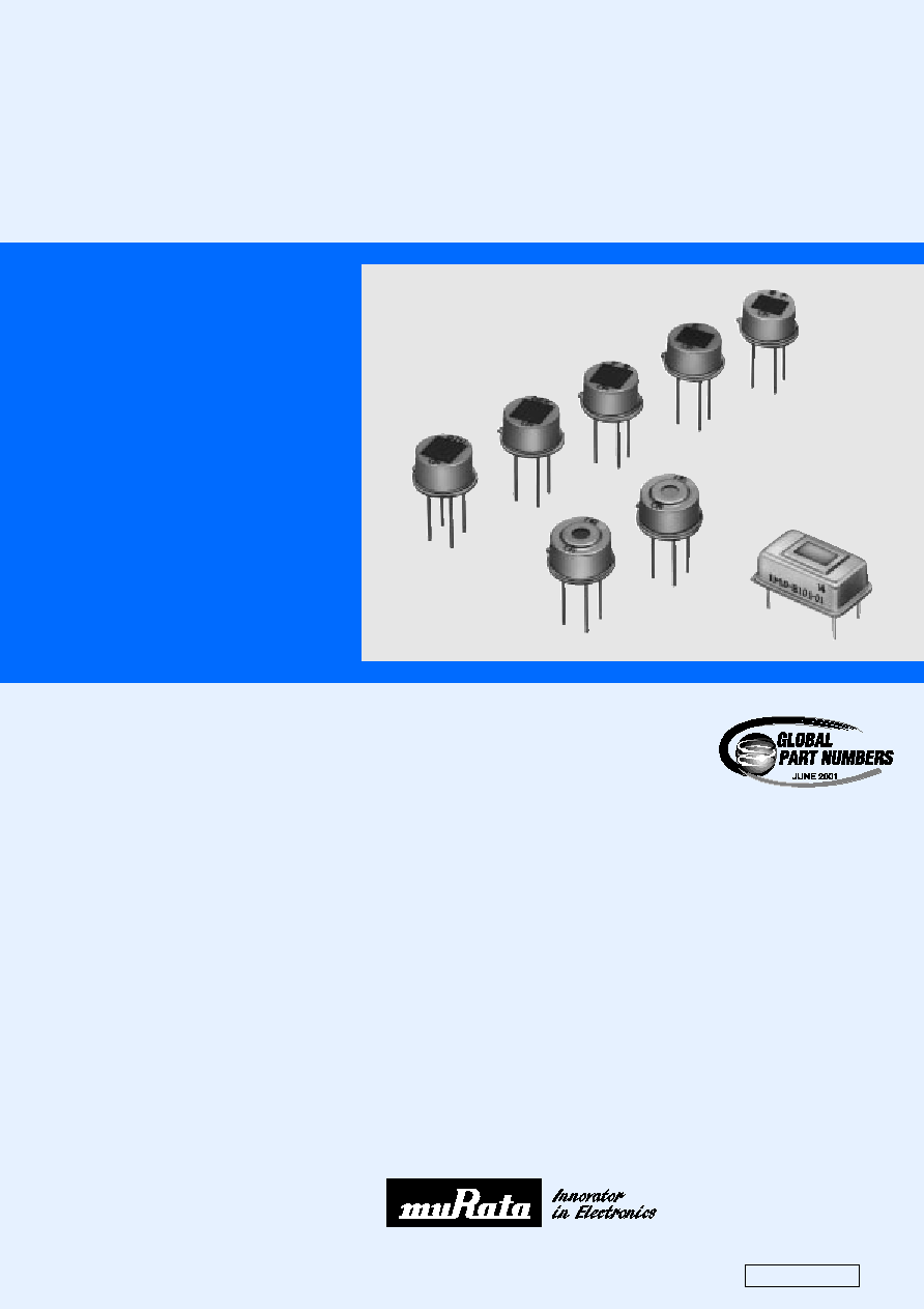
Pyroelectric Infrared Sensors & Sensor Modules
PYROELECTRIC
INFRARED
SENSORS
&
SENSOR
MODULES
Murata
Manufacturing Co., Ltd.
Please read CAUTION and Notice in this catalog for safety. This catalog has only typical specifications. Therefore you are requested
to approve our product specification or to transact the approval sheet for product specification, before your ordering.
S21E3.pdf 03.2.17
CONTENTS
Dual Type Pyroelectric Infrared Sensor IRA-E700 Series
Quad Type Pyroelectric Infrared Sensor IRA-E900 Series
Quad Type Pyroelectric Infrared Sensor IRA-E940ST1 Series
Temperatue Compensation Single Type Pyroelectric Infrared Sensor
IRA-E420 Series
Pyroelectric Infrared Sensor Module IMD Series
1
2
3
4
5
6
11
13
1
2
3
4
5
Notice
Pyroelectric Infrared Sensor IRA Series Characteristics Data
Part Numbering
Recycled Paper
Please read CAUTION and Notice in this catalog for safety. This catalog has only typical specifications. Therefore you are requested
to approve our product specification or to transact the approval sheet for product specification, before your ordering.
S21E3.pdf 03.2.17
Please read CAUTION and Notice in this catalog for safety. This catalog has only typical specifications. Therefore you are requested
to approve our product specification or to transact the approval sheet for product specification, before your ordering.
S21E3.pdf 03.2.17
1
o
Part Numbering
Pyroelectric Infrared Sensor
qProduct ID
wType
eCharacteristics
rIndividual Specification Code
* Global Part Number shows only an example which might be
different from actual part number.
* "
eCharacteristics" and "rIndividual Specification Code" might
have different digit number from actual Global Part Number.
Sensor Module
qProduct ID
wType
eCharacteristics
rIndividual Specification Code
* Global Part Number shows only an example which might be
different from actual part number.
* "
eCharacteristics" and "rIndividual Specification Code" might
have different digit number from actual Global Part Number.
IR
(Global Part Number)
A-
E710ST
1
q w
e
r
IM
(Global Part Number)
D-
B101-
01
q w
e
r
Please read CAUTION and Notice in this catalog for safety. This catalog has only typical specifications. Therefore you are requested
to approve our product specification or to transact the approval sheet for product specification, before your ordering.
S21E3.pdf 03.2.17
1
2
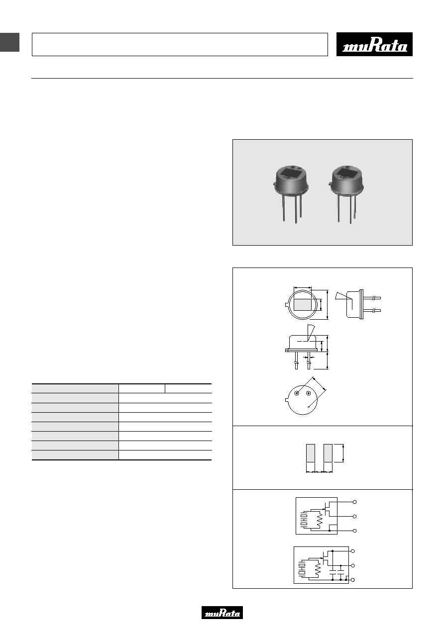
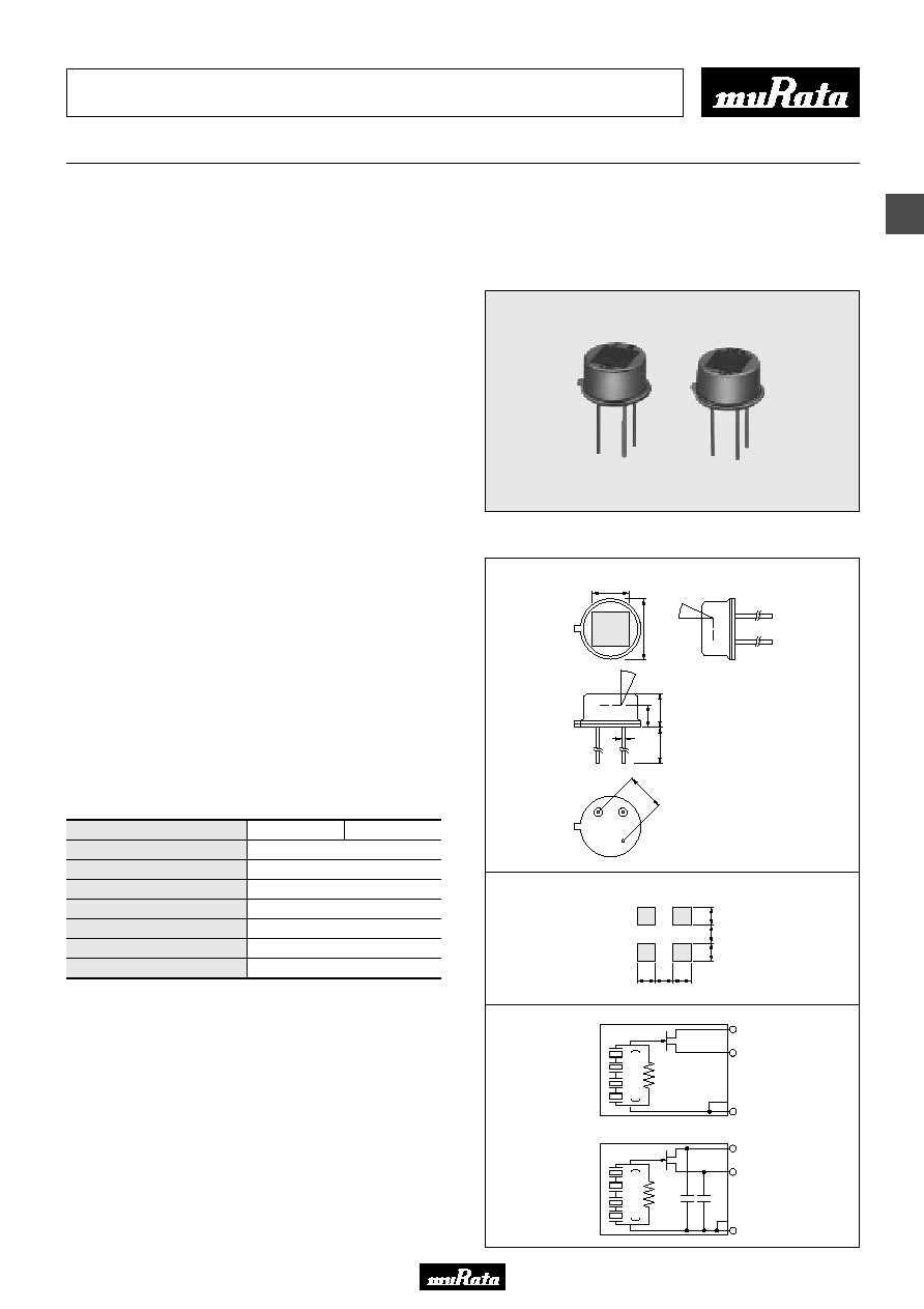
Dual Type Pyroelectric Infrared Sensor
IRA-E700
Series
Pyroelectric Infrared Sensors
Pyroelectric infrared sensors, IRA series, exhibit high
sensitivity and reliable performance made possible by
Murata's ceramic technology and Hybrid IC technique
expertise developed over many years.
IRA-E700 series realizes cost benefits and higher
performance with a new infrared sensor element of
improved material parameters and fabrication.
IRA-E700 series is available in two types.
IRA-E710ST0 has enhanced immunity to RFI (Radio
Frequency Interference).
! Features
1. High sensitivity and excellent S/N ratio
2. High stability to the temperature change
3. Slight movement can be detectable.
4. High immunity to the external noise (Vibration, RFI etc.)
5. Custom design is available.
6. Higher in cost-performance
! Applications
1. Security
2. Lighting appliances
3. Household or other appliances
!Rating (25∞C)
! Dimensions & Circuit Diagrams
g
s
RG
d
g
s
RG
d
5.0
±
0.05
d
s
g
9
.
2
4.7
±
0.1
3
.
7
±
0.
1
11
.0
±
2
0.45
±
0.05
4
.
7
45
∞
45
∞
3
.
6
1.0 1.0 1.0
2
.0
Pyroelectric element
IRA-E700ST0
(in mm)
Specified on the bottom of stem
General Tolerance : ±0.2
(in mm)
IRA-E710ST0
Part Number
Responsivity (500K, 1Hz, 1Hz)
Field of View
Optical Filter
Electrode
Supply Voltage
Operating Temperature
Storage Temperature
4.3mV
p-p
(Typ.)
1
=
2
=45∞
5µm long-pass
(2.0
Z
1.0mm)
Z
2
2 to 15V
-40 to 70
D
-40 to 85
D
IRA-E700ST0
IRA-E710ST0
Please read CAUTION and Notice in this catalog for safety. This catalog has only typical specifications. Therefore you are requested
to approve our product specification or to transact the approval sheet for product specification, before your ordering.
S21E3.pdf 03.2.17
2
3
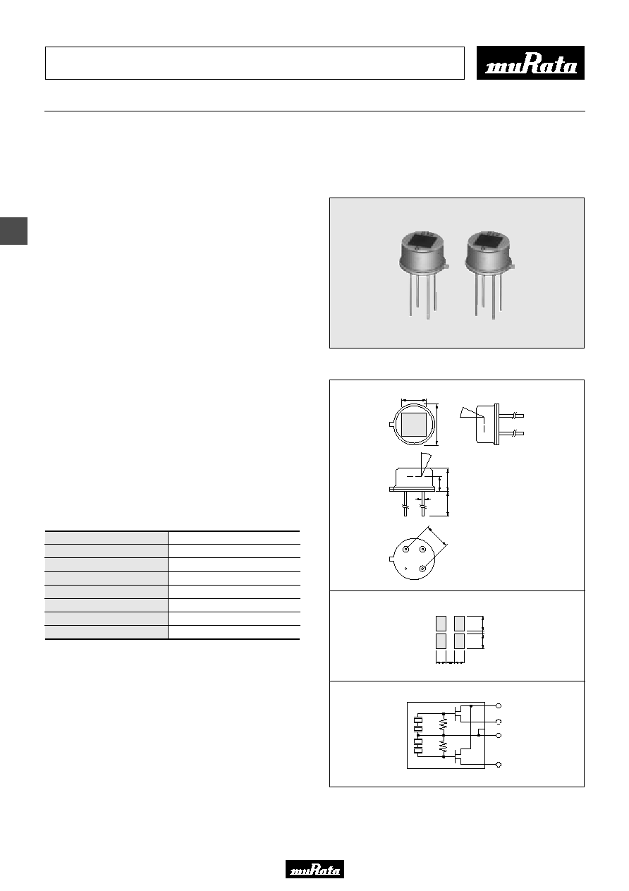
Quad Type Pyroelectric Infrared Sensor
IRA-E900
Series
Pyroelectric Infrared Sensors
Pyroelectric infrared sensors, IRA series, exhibit high
sensitivity and reliable performance made possible by
Murata's ceramic technology and Hybrid IC technique
expertise developed over many years.
IRA-E900 series realizes cost benefits and higher
performance with a new infrared sensor element of
improved material parameters and fabrication.
IRA-E900 series is available in two types.
IRA-E910ST1 has enhanced immunity to RFI (Radio
Frequency Interference).
! Features
1. High sensitivity and excellent S/N ratio
2. High stability to the temperature change
3. Slight movement can be detectable.
4. Non directional sensing with wide F.O.V.
5. High immunity to the external noise (Vibration, RFI etc.)
6. Custom design is available.
7. Higher in cost-performance
! Applications
1. Security
2. Lighting appliances
3. Household or other appliances
! Rating (25∞C)
! Dimensions & Circuit Diagrams
5.08
±
0.05
d
s
g
1.1 1.0 1.1
9
.
2
4.7
±
0.1
1
.
1
1
.0
1
.
1
g
s
RG
Y
W
W
Y
Y
W
W
Y
W
Y
Y
W
W
Y
Y
W
d
g
s
RG
Y
W
W
Y
Y
W
W
Y
W
Y
Y
W
W
Y
Y
W
d
11
.0
±
2
0.45
±
0.05
4
.
7
41
∞
3
.
6
41
∞
Pyroelectric element
IRA-E900ST1
(in mm)
(in mm)
IRA-E910ST1
Specified on the bottom of stem
General Tolerance : ±0.2
Part Number
Responsivity (500K, 1Hz, 1Hz)
Field of View
Optical Filter
Electrode
Supply Voltage
Operating Temperature
Storage Temperature
3.3mV
p-p
(Typ.)
1
=
2
=41∞
5µm long-pass
(1.1
Z
1.1mm)
Z
4
3 to 15V
-25 to 55
D
-40 to 85
D
IRA-E900ST1
IRA-E910ST1
Please read CAUTION and Notice in this catalog for safety. This catalog has only typical specifications. Therefore you are requested
to approve our product specification or to transact the approval sheet for product specification, before your ordering.
S21E3.pdf 03.2.17
3
4
Quad Type Pyroelectric Infrared Sensor
IRA-E940ST1
Series
Pyroelectric Infrared Sensors
Pyroelectric infrared sensors, IRA series, exhibit high
sensitivity and reliable performance made possible by
Murata's ceramic technology and Hybrid IC technique
expertise developed over many years.
IRA-E940ST1 realizes cost benefits and higher performance
with a new infrared sensor element of improved material
parameters and fabrication.
IRA-E940ST1 which has quad elements and 2 outputs will
detect the human body more correctly with OR/AND logic
circuit.
! Features
1. High sensitivity and excellent S/N ratio
2. High stability to the temperature change
3. High immunity to the external noise (Vibration, RFI etc.)
4. Higher in cost-performance
5. Custom design is available.
! Applications
1. Security
2. Lighting appliances
3. Household or other appliances
! Rating (25∞C)
! Dimensions & Circuit Diagrams
5.08
±
0.05
s1 d
s2
g
1.0 0.8
(
Y
)
W
(
Y
)
W
Y
(
W
)
Y
(
W
)
1.0
9
.
2
4.7
±
0.1
1
.
3
5
0.
3
1
.
3
5
RG
RG
s1
d
s2
g
11
.0
±
2
0.45
±
0.05
4
.
7
55
∞
3
.
6
50
∞
Pyroelectric element
(in mm)
(in mm)
Specified on the bottom of stem
General Tolerance : ±0.2
Part Number
Responsivity (500K, 1Hz, 1Hz)
Field of View
Optical Filter
Electrode
Supply Voltage
Operating Temperature
Storage Temperature
3.3mV
p-p
(Typ.)
1
=55∞,
2
=50∞
5µm long-pass
(1.35
Z
1.0mm)
Z
4
2 to 15V
-25 to 55
D
-40 to 85
D
IRA-E940ST1
Please read CAUTION and Notice in this catalog for safety. This catalog has only typical specifications. Therefore you are requested
to approve our product specification or to transact the approval sheet for product specification, before your ordering.
S21E3.pdf 03.2.17
4
5
Temperature Compensation Single Type Pyroelectric Infrared Sensor
IRA-E420
Series
Pyroelectric Infrared Sensors
Single type pyroelectric infrared sensors IRA-E420 series,
have a temperature compensation element.
They are suitable for flame detection and gas detection.
! Features
1. High stability against abrupt ambient temperature change
2. High immunity to the external noise (Vibration, RFI etc.)
3. Custom design is available with varying optical filter.
! Applications
! Rating (25∞C)
! Dimensions & Circuit Diagrams
Part Number
IRA-E420S1
IRA-E420QW1
Silicon
4.3µm band-pass
1-15µm infrared detection
Flame detection
Optical Filter
Applications
*
700K, 5Hz, 1Hz
5.08
±
0.05
d
s
g
11
.0
±
2
1.6
Pyroelectric element
0.45
±
0.05
4
.
9
9
.
2
2.4
±
0.1
17
∞
17
∞
3
.
6
RG
s
g
d
(in mm)
(in mm)
Specified on the bottom of stem
General Tolerance : ±0.2
Part Number
Responsivity (500K, 1Hz, 1Hz)
Field of View
Optical Filter
Electrode
Supply Voltage
Operating Temperature
Storage Temperature
3.4mV
p-p
(Typ.)
Silicon
-25 to 70
D
IRA-E420S1
1
=
2
=17∞
1.6mm
3 to 15V
-30 to 100
D
1.3mV
p-p
(Typ.)
*
4.3µm band-pass
-25 to 55
D
IRA-E420QW1
Please read CAUTION and Notice in this catalog for safety. This catalog has only typical specifications. Therefore you are requested
to approve our product specification or to transact the approval sheet for product specification, before your ordering.
S21E3.pdf 03.2.17
4
6
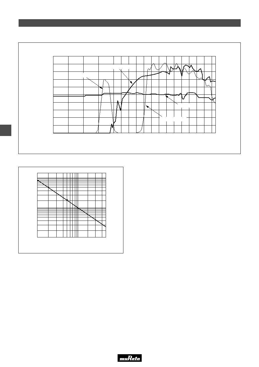
Pyroelectric Infrared Sensor IRA Series Characteristics Data
! Spectral Response of Window Materials
! Frequency Characteristics
2.5
4000
3500
3000
2500
2000
1800
Wave number (cm
-1
)
T
r
a
n
s
m
i
t
t
a
n
c
e
(
%
)
Wave length (
µ
m)
4.3
µ
m Band-Pass Filter
7
µ
m Long-Pass Filter
Silicon Filter
1600
1400
1200
1000
800
100
0
20
40
60
80
3.0
4.0
5.0
6.0
7.0
8.0
10.0
12.0
5
µ
m Long-Pass Filter
1.0
Chopping Frequency (Hz)
R
e
l
a
t
i
v
e
R
e
s
p
o
n
s
i
v
i
t
y
(
R
V
)
1
10
10
Please read CAUTION and Notice in this catalog for safety. This catalog has only typical specifications. Therefore you are requested
to approve our product specification or to transact the approval sheet for product specification, before your ordering.
S21E3.pdf 03.2.17
4
7
Pyroelectric Infrared Sensor IRA Series Characteristics Data
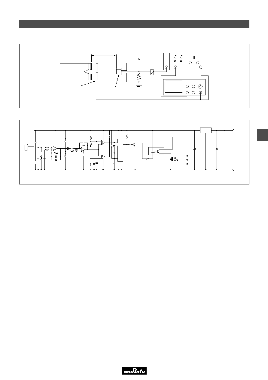
! Test Method of Sensitivity
! Typical Application Circuit (Human detection)
140mm
Black Body
500K
Mechanical Chopper
1Hz
Infrared Sensor
Oscilloscope
g
s
47k
W
22µF
d
W
5V
Lock-in Amplifier (1Hz)
D
g
B102K
LM358
330k
B222K
260k
100k
4
8
1
C
B103K
R
5
2
6
7
3
100k
2SD596
µ
PD5555G
100k
1k
Photo Cuppler
Relay
220k
220k
NJM
2903M
330k
3.3
µ
16V
10
µ
16V
100k
100k
S
B102K
100k
120k
4.7
µ
16V
1
120k
B102K
10M
10M
B222K
1S184
B102K
W
W
W W
10
µ
16V
LM358
1S184
100
µ
16V
100
µ
16V
9
Y
15
GND
78L05
3 Terminal Regulater
T
H
=1.1
Z
C (
µ
F)
Z
R (M
) second
W
W
W
Please read CAUTION and Notice in this catalog for safety. This catalog has only typical specifications. Therefore you are requested
to approve our product specification or to transact the approval sheet for product specification, before your ordering.
S21E3.pdf 03.2.17
4
8
Pyroelectric Infrared Sensor IRA Series Characteristics Data
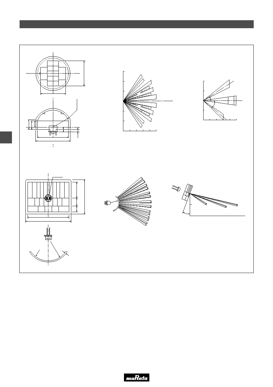
! Fresnel Lens for Human Body Detection
m
3.0
2.0
1.0
0
1.0
2.0
3.0
1.0
2.0
3.0
4.0 5.0 m
1.0
2.0
7.7m
29.6R
9m
10m
9m
7.7m
2m
1m
1.6m
3.5m
10m
12
∞
3.0
4.0
B
B' A
C
C'
C'
C'
B'
B'
B
D
B
C
C
D'
D'
D
A
A
D, D'
E, E'
30
∞
22.5
∞
5.0 m
m
4.0
3.0
2.0
1.0
0
Horizontal Area
Vertical Area
Horizontal Area
Vertical Area
Sensor
29.6R
0.7max.
8
10
21.
5
44
.
5
Lens plane
Sensor
1
6
.3
C
D
D
'
E
E
'
B
A
B'
C
'
2.2
4
11.
6
4
R
3.
6
0
6
.
4
5
.0
3.
6
4
Cross-Sectional View
E'
E
16.0
21.0
20.0
51.5
56.5
(in mm)
(in mm)
PPGI0601
PPGI0902
Please read CAUTION and Notice in this catalog for safety. This catalog has only typical specifications. Therefore you are requested
to approve our product specification or to transact the approval sheet for product specification, before your ordering.
S21E3.pdf 03.2.17
4
9
Pyroelectric Infrared Sensor IRA Series Characteristics Data
16.5
6
12.9SR
Y
C12
C2
C11
C3
C1
C10
X
C9
C5
C4
Z
0.8m
2.2m
2
.
5
m
0
.
5
m
Y
Y
3
2
1
0
1
2
3
C
(
m
)
B
A
B
C
A : 0
∞
B : 21.8
∞
C : 48
∞
C8
C6
C7
B1
B4
B5
B6
B3
B2
12
.1S
R
3
3.6
P
y
r
o
e
l
e
c
t
r
i
c
e
l
e
m
e
n
t
2
3
23
T
0.2
21.4
19.4
A
B
C
Detection area on the floor
B : 60
∞
pitch
C : 30
∞
pitch
Freshel lens are available upon request.
(in mm)
PPGI0626
Please read CAUTION and Notice in this catalog for safety. This catalog has only typical specifications. Therefore you are requested
to approve our product specification or to transact the approval sheet for product specification, before your ordering.
S21E3.pdf 03.2.17
4
10
Pyroelectric Infrared Sensor IRA Series Characteristics Data
After test completion, leave for three hours in
normal humidity temperature conditions, and
then measure.
1. External appearance:
No significant damage.
2. Sensitivity:
Tolerance within 20% deviation from original
value.
3. Noise:
Maximum tolerance
W
100mV of original value
No generation of bubbles.
More than 95% of the terminal should be covered
by solder.
! Reliability Test
IRA-E700 series, IRA-E900 series
IRA-E420 series
Item
High Temperature
Low Temperature
Humidity
Heat Cycle
Vibration
Shock
Soldering Heat
Hermetic Sealing
Solderability
100
D
for 500 hrs.
Y
40
D
for 500 hrs.
60
D
, 95% RH for 500 hrs.
20 times of following cycle.
Y
25
D
, 30min.
e
Room temp., 30min.
h
g
Room temp., 30min.
f
55
D
, 30min.
Apply vibration of amplitude of 1.5mm with 10 to 55Hz band to each of 3
perpendicular directions for 60min.
Apply shock of 100G sinewave by standard shock tester to each of 3
perpendicular directions.
Immerse up to 3.0mm from can case in solder bath of 260
T
5
D
for 10
T
1 s.
Conform to MIL-STD-202F chapter 112D, condition D.
Immerse in fluorocarbon bath (FC-40) of 125
T
5
D
for 20 s.
Conform to MIL-STD-202F chapter 208B.
Immerse in rosin flax and Immerse up to 2.0 to 2.5mm from can case in
solder bath of 230
T
5
D
for 5
T
0.5 s.
Test Conditions
Criteria
Item
High Temperature
Low Temperature
Humidity
Heat Cycle
Vibration
Shock
Soldering Heat
Hermetic Sealing
Solderability
100
D
for 500 hrs.
Y
30
D
for 500 hrs.
60
D
, 95% RH for 500 hrs.
20 times of following cycle.
Y
25
D
, 30min.
e
Room temp., 30min.
h
g
Room temp., 30min.
f
55
D
, 30min.
Apply vibration of amplitude of 1.5mm with 10 to 55Hz band to each of 3
perpendicular directions for 60min.
Apply shock of 100G sinewave by standard shock tester to each of 3
perpendicular directions.
Immerse up to 3.0mm from can case in solder bath of 260
T
5∞C for 10
T
1 s.
Conform to MIL-STD-202F chapter 112D, condition D.
Immerse in fluorocarbon bath (FC-40) of 125
T
5
D
for 20 s.
Conform to MIL-STD-202F chapter 208B.
Immerse in rosin flux and Immerse up to 2.0 to 2.5mm from can case in
solder bath of 230
T
5
D
for 5
T
0.5 s.
Test Conditions
After test completion, leave for three hours in
normal humidity temperature conditions, and
then measure.
1. External appearance:
No significant damage.
2. Sensitivity:
Tolerance within 20% deviation from original
value.
3. Noise:
Maximum tolerance
W
100mV of original value
No generation of bubbles.
More than 95% of the terminal should be covered
by solder.
Criteria
Please read CAUTION and Notice in this catalog for safety. This catalog has only typical specifications. Therefore you are requested
to approve our product specification or to transact the approval sheet for product specification, before your ordering.
S21E3.pdf 03.2.17
5
11
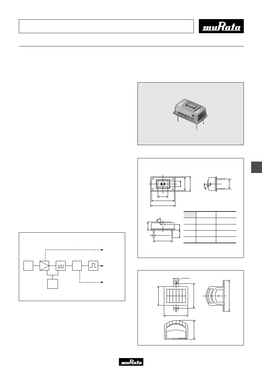
Pyroelectric Infrared Sensor Module
IMD
Series
Pyroelectric Infrared Sensor Modules
Newly Developed Modules with Lower
Power Consumption and Extra Features.
The IMD Series is comprised of an amplifier and high
performance infrared sensor modules in compact,
hermetically sealed metal can packages.
Power consumption of the module is very low and a Fresnel
lens is included in the module.
Analog & Digital Output Model (IMD-B101-01) and Digital
Output & Brightness Sensor (CdS) Input Model (IMD-B102-
01) are available for different applications.
! Features
1. With the fresnel lens, the sensor is able to detect the
human body at a distance of 5m through angles of
119∞
Z
38∞ (Max.)
2. The modules have a compact size of 20.3
Z
12.6
Z
7.8mm.
3. The modules incorporate an amplifier and a single
processing circuit.
4. They have outstanding reliability and EMI characteristics.
5. They have low power consumption.
! Applications
1. Automatic light switches
2. On/off controls for household appliances, industrial
equipment and office equipment
3. Amusement devices (Games, Toys, etc.)
!Block Diagram
! Dimensions
! Fresnel Lens
7
.
6
2
3
5
∞
1
2
.
6
1
0
.
8
4
.
7
20.3
18.4
8.3
15.24
0.45
±
0.05
7
.
8
5
.
1
7
.
0
±
2
45
∞
Pyroelectric element
2
Z
1mm Dual element
(1)
(2)
(4)
(3)
Pin No. IMD-B101-01 IMD-B102-01
(1)
GND
GND
(3)
Vcc
Vcc
(2)
Analog Output
CdS Input
(4)
Digital Output
Digital Output
(in mm)
(in mm)
Amplifier
Sensor
Comparator
Output Circuit
Digital Output
Analog Output
Cds Input
Gate
Circuit
Stabilized
Power
Supply
IMD-B102-01
IMD-B101-01
5.0
22.5
2-2
1
6
.
4
2
1
.
5
1
6
.
5
2
6
.
5
IMD-FL01W (White)
IMD-FL01G (Gray)
Specified on the bottom of stem
General Tolerance : ±0.2
General Tolerance : ±0.4
Please read CAUTION and Notice in this catalog for safety. This catalog has only typical specifications. Therefore you are requested
to approve our product specification or to transact the approval sheet for product specification, before your ordering.
S21E3.pdf 03.2.17
5
12
Pyroelectric Infrared Sensor Module IMD Series
! Reliability Test
Item
High Temperature
Low Temperature
Humidity
Heat Cycle
Vibration
Shock
Soldering Heat
Hermetic Sealing
60
D
for 500 hrs.
Y
20
D
for 500 hrs.
60
D
, 95% RH for 150 hrs.
20 times of following cycle.
Y
20
D
, 30min.
e
Room temp., 30min
h
g
Room temp., 30min.
f
60
D
, 30min.
Apply vibration of amplitude of 1.5mm with 10 to 55Hz band to each of 3
perpendicular directions for 2 hrs.
Apply shock of 30G sinewave by standard shock tester to each of 3
perpendicular directions for 5 times.
Immerse up to 3.0mm from can case in solder bath of 260
T
5
D
for 10
T
1 s.
Conform to MIL-STD-202F chapter 112D, condition D.
Immerse in fluorocarbon bath (FC-40) of 125
T
5
D
for 20 s.
Test Conditions
After test completion, leave for three hours in
normal humidity temperature conditions, and
then measure.
1. External appearance:
No significant damage.
2. Sensitivity:
Min. 70% of original value.
3. Current consumption:
Within rated value.
No generation of bubbles.
Criteria
! Max. Rating (25∞C)
! Rating (25∞C)
! Timing Chart (IMD-B101-01)
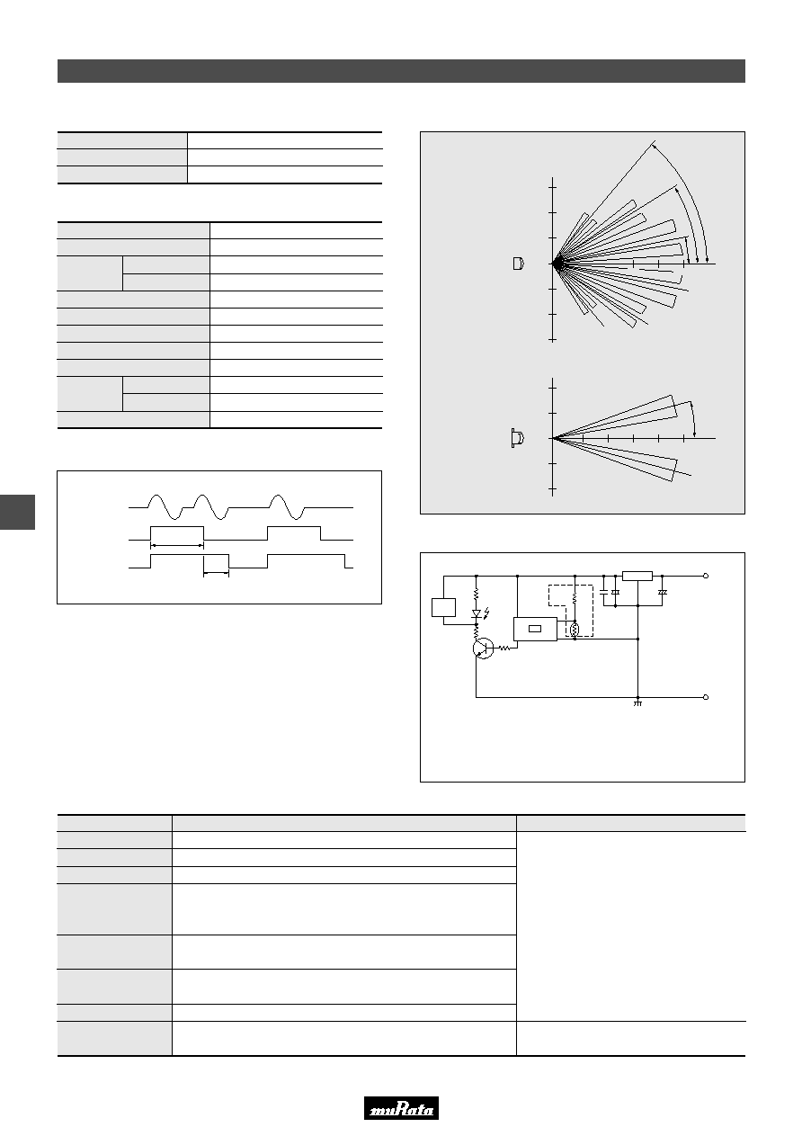
! Detection Area (With Fresnel Lens)
! Typical Application (IMD-B102-01)
Horizontal Area
Vertical Area
m
2.0
1.0
0
1.0
2.0
m
2.0
1.0
0
1.0
2.0
3.0
5
2
∞
3
4
∞
1
2
.
5
∞
5.0m
3.0
5.0m
1
5
∞
P
1
P
2
Analog Output
Digital Output
Prohibited Period
∑CdS Input is required to be Vcc 3.9
W
0.2V/
Y
0.4V or higer to operate.
∑IMD-B101-01 generates analog output at Pin (2).
W
Y
W
Y
200 to
500k
22
Y
220
µ
F
78L05
8
Y
15V
3
LOAD
4
2
0.1
µ
100
µ
F
1
CdS
500
R
L
U
1k
Max. Supply Voltage
Operating Temp. Range
Storage Temp. Range
5.5V
Y
10 to
W
50
D
(Without condensation)
Y
20 to
W
60
D
Items
Supply Voltage
Output Terminal
Output Current
Output Pulse Width
(P1)
Prohibited Time
(P2)
Wave Length Range
Detection Range
2.6
Y
5.5V
30
Y
60µA
50
Y
120µA
C-MOS
1mA
1.0
Y
3.0s
F
3.0s
5
Y
14µm
1m
5m
119∞
Z
38∞ (Max.)
Current
Consumption
Detection
Length
Ready Period
Active Period
Without Lens
With IMD-FL01W/G

Please read CAUTION and Notice in this catalog for safety. This catalog has only typical specifications. Therefore you are requested
to approve our product specification or to transact the approval sheet for product specification, before your ordering.
S21E3.pdf 03.2.17
13
Notice
1. Caution in design
(1) Please make sure that your product has been evaluated
and confirmed against your specifications when our
product is mounted to your product.
(2) Be sure to provide an appropriate fail-safe function on
your product to prevent a second damage that may be
caused by the abnormal function or the failure of our
product.
(3) In case of outdoor use, suitable optical filter and water
and humidity proof structure should be applied.
(4) To prevent failure or malfunction, please use a stabilized
power supply.
(5) Please avoid using the sensor in the following conditions
because it may cause failure or malfunction.
(a) in such a fluid as water, alcohol etc. corrosive gas
(SO
2
, Cl
2
, NO
X
etc.) or sea breeze
(b) in high humidity
(c) in a place exposed directly to sun light or headlight of
automobile
(d) in a place exposed to rapid ambient temperature
change
(e) in a place exposed directly to an air-conditioner or
heat vent
(f) strong vibrations
(g) in a place exposed to strong electromagnetic field
(h) in such a place where infrared ray is shaded
(i) in any other place similar to the above (a) through (h)
2. Caution in mounting
(1) Soldering
(a) Hand soldering should be applied.
(b) Soldering should be done quickly as following.
(c) Soldering flux should be rosin flux and not contain
more than 0.2wt% chlorine.
Soldering flux should be removed after soldering.
(2) Cleaning
Soldering flux should be removed after soldering.
Soldering flux may cause malfunction or degradation of
character unless sufficiently cleaned.
3. Caution in handling and storage
(1) The optical filter of the sensor should not be scratched or
soiled.
(2) Strong shock should be avoided.
(3) Electrostatics and strong electromagnetic field should be
avoided.
(4) The sensor should be kept on conductive sponge.
(5) High temperature, high humidity, fluid such as water or
alcohol etc., corrosive gas (SO
2
, Cl
2
, NO
X
etc.) and sea
breeze should be avoided.
! Notice
Temperature of soldering iron : 350∞C
Distance from can case
1
Y
3mm
Over 3mm
Period of time
Within 3seconds per point
Within 10seconds per point

Note:
1. Export Control
<
For customers outside Japan
>
Murata products should not be used or sold for use in the development, production, stockpiling or utilization of any conventional weapons or mass-destructive
weapons (nuclear weapons, chemical or biological weapons, or missiles), or any other weapons.
<
For customers in Japan
>
For products which are controlled items subject to the "Foreign Exchange and Foreign Trade Law" of Japan, the export license specified by the law is required
for export.
2. Please contact our sales representatives or product engineers before using the products in this catalog for the applications listed below, which require especially
high reliability for the prevention of defects which might directly damage to a third party's life, body or property, or when one of our products is intended for use
in applications other than those specified in this catalog.
q
Aircraft equipment
w
Aerospace equipment
e
Undersea equipment
r
Power plant equipment
t
Medical equipment
y
Transportation equipment (vehicles, trains, ships, etc.)
u
Traffic signal equipment
i
Disaster prevention / crime prevention equipment
o
Data-processing equipment
!0
Application of similar complexity and/or reliability requirements to the applications listed in the above
3. Product specifications in this catalog are as of January 2003. They are subject to change or our products in it may be discontinued without advance notice.
Please check with our sales representatives or product engineers before ordering. If there are any questions, please contact our sales representatives or
product engineers.
4. Please read rating and CAUTION (for storage, operating, rating, soldering, mounting and handling) in this catalog to prevent smoking and/or burning, etc.
5. This catalog has only typical specifications because there is no space for detailed specifications. Therefore, please approve our product specifications or
transact the approval sheet for product specifications before ordering.
6. Please note that unless otherwise specified, we shall assume no responsibility whatsoever for any conflict or dispute that may occur in connection with the effect
of our and/or a third party's intellectual property rights and other related rights in consideration of your use of our products and/or information described or
contained in our catalogs. In this connection, no representation shall be made to the effect that any third parties are authorized to use the rights mentioned
above under licenses without our consent.
7. No ozone depleting substances (ODS) under the Montreal Protocol are used in our manufacturing process.
International Division
3-29-12, Shibuya, Shibuya-ku, Tokyo 150-0002, Japan
Phone: 81-3-5469-6123 Fax: 81-3-5469-6155 E-mail: intl@murata.co.jp
Head Office
2-26-10, Tenjin Nagaokakyo-shi, Kyoto 617-8555, Japan Phone: 81-75-951-9111
http://www.murata.com/
Please read CAUTION and Notice in this catalog for safety. This catalog has only typical specifications. Therefore you are requested
to approve our product specification or to transact the approval sheet for product specification, before your ordering.
S21E3.pdf 03.2.17