118
CG01-J
APPLICATION SPECIFIC CAPACITORS
HIGH FREQUENCY CERAMIC CAPACITORS
MA/MB Series
OUTSTANDING CHARACTERISTICS
I
Miniature size
I
Very high Q at high frequencies
I
High RF power capabilities
I
Impervious to environmental conditions
I
Low dissipation factors
I
Excellent retrace capability (not applicable for X7R styles)
I
High temperature stability
I
Low noise
I
Meets Mil-55681 with respect to: Shock, Vibration,
Moisture Resistance, Solderability, Barometric Pressure,
Temperature Cycling, Immersion and Salt Spray
ADDITIONAL FEATURES
I
Packaging options
I
Lot processing data available
MA SERIES
For filtering, coupling and impedance matching in most
RF circuits, the MA Series chips and leaded devices offer
outstanding performance and reliability with the greatest
range of values and configurations. MA Series capacitors
can be supplied with military equivalent screening. Please
consult our factory.
MA Series ceramic fixed capacitors are miniature, high
performance precision components having extremely high Q
and high power capabilities from low frequencies to gigahertz
ranges. These "low loss" multilayer capacitors are extremely
stable with respect to variations in temperature, voltage and
frequency.
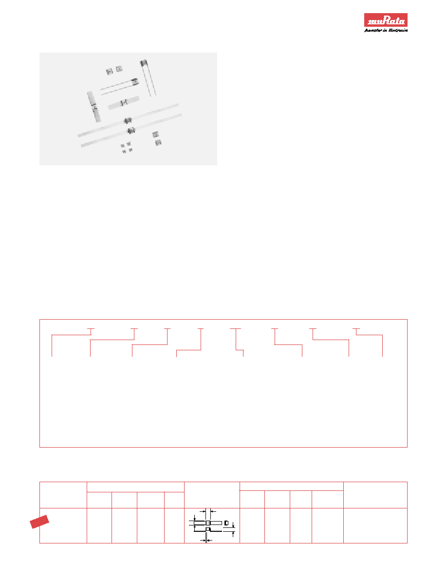
MA Series capacitors are designed for miniature
state-of-the-art circuit applications. They are small,
easy to apply and have excellent reliability. Units are
available in ultra-miniature case size 1 (1.4 x 1.4 x 1.4mm)
or miniature case size 2 (2.8 x 2.8 x 2.5mm). Standard
case size 1 units are available as chips. Standard case
size 2 units are available as chips and also in leaded
configurations.
Clean-room manufacturing technology assures product
reliability and automated processing reduces costs and
cycle time. Key stages of the operation are monitored
and controlled with the latest SPC techniques. Flexibility in
design allows the production of non-standard values, while
maintaining consistent quality objectives.
Please contact the factory for availability of special
configurations or high-reliability screening.
M
A
1
8
101
J
A
N
CUBIC
A-STD SERIES
DIMENSIONAL
TERMINATION
CAPACITANCE
TOLERANCES:
A: NO
7" Reel
MONOLITHIC
B-ULTRA AND
T.C.
CODE
CODE:
CODE:
Expressed
*B: ±0.1pF
MARKING
Plastic
HIGH Q
1: P90 Case 1
0: Chip
in picofarads and
*C : ±0.25pF
B: MARKING Tape
5: COG Case 1
1: Pellet
identified by a three-digit *D: ±0.5pF
Cap. Code
7: X7R Case 1
2: Microstrip
number. First two digits
F : ±1%
& Tol.
2: P90 Case 2
3: Radial Ribbon
represent significant
G: ±2%
Logo if space
6: COG Case 2
4: Radial Wire
figures. Last digit
J : ±5%
permits
8: X7R Case 2
5: Axial Ribbon
specifies the number
K : ±10%
Non XR7
6: Narrow Axial Ribbon
of zeros to follow. For
M: ±20%
styles only
7: Axial Wire
values below 10pF,
Z: +80%, ≠20%
8: Nickel Interfaced Pellet
the letter "R" is used
9: Nickel Interfaced Chip
as the decimal point
*Available
and the last digit
below 10pf
becomes significant.
only
PART NUMBERING SYSTEM ≠ CASE SIZE 1 & CASE SIZE 2
Type
Dimensions: mm
Style
P90 ± 20 P90 ± 30
COG
X7R
Configuration
L ± 0.38* W ± 0.38* T ± .038
Band
Termination
Y
Silver Ribbon:
Raised
MA22-6
MB22-6
MA62-6
MA82-6
Length: 6.35 typical
Micro-Strip
3.4
2.8
2.8
0.38 ± .25
Width: 2.3 ± .13
Thickness: 0.1 ± .05
SPECIAL LEAD CONFIGURATION FOR FLEX BOARDS
NOTE: Targeted for flex circuit boards, the MA22-6 version of the MA22 has an upraised lead configuration. The lead bends
when flexing the board after assembly so that minimal stress is placed on the component.
T
W
L
Y
NE
W
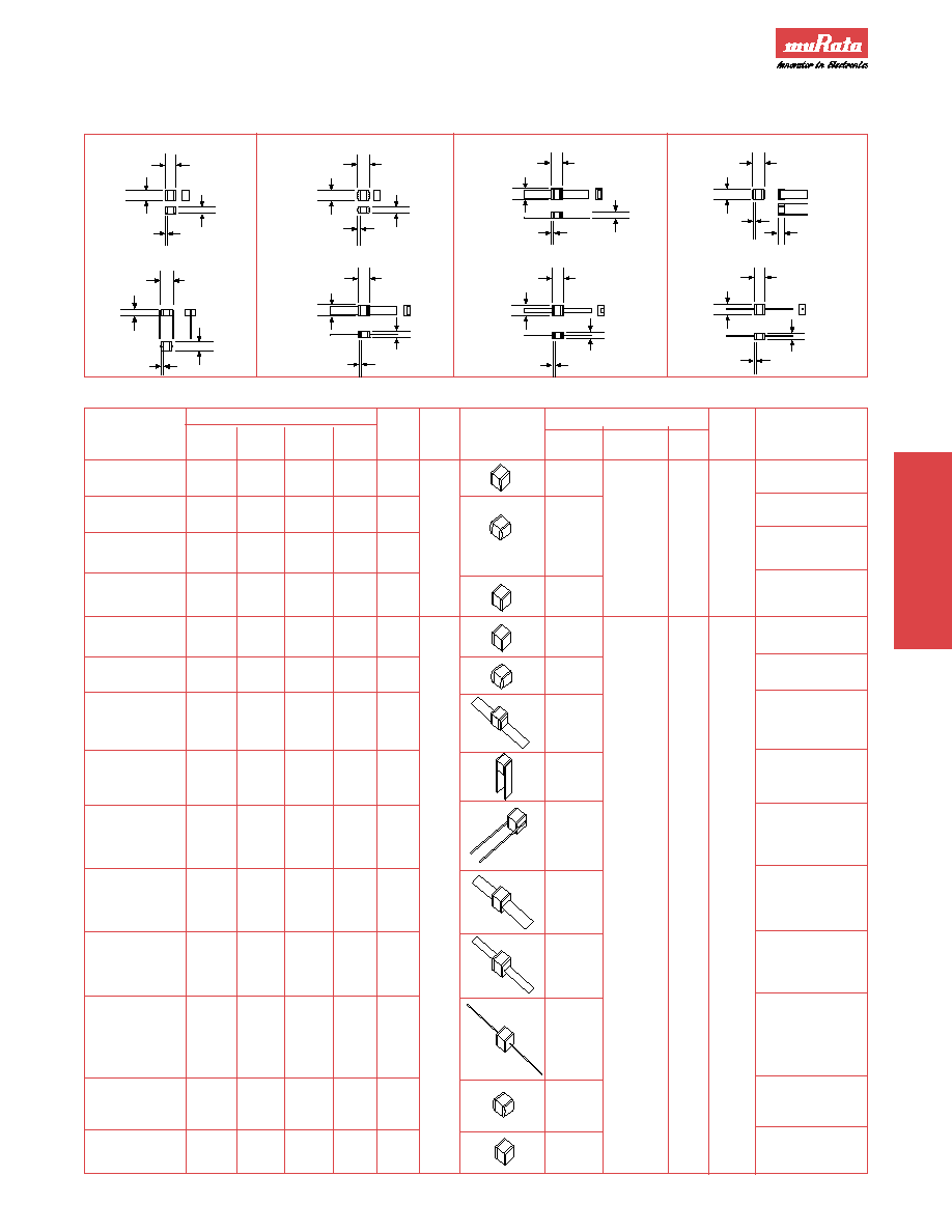
Fig. 1 Chip
Fig. 5 Radial Wire
Fig. 2 Pellet
Fig. 6 Axial Ribbon
Fig. 3 Micro-Strip
Fig. 7 Narrow Axial Ribbon
Fig. 4 Radial Ribbon
Fig. 8 Axial Wire
DIMENSIONS
Y
L
T
W
L
W
T
Y
T
W
L
Y
W
L
Y
T
W
L
Y
T
Y
W
L
T
Y
W
L
T
Y
W
L
T
*Except where Tolerance is shown.
Lead lengths are typical widths ±0.1mm, thickness & dia. ±0.05mm.
All leaded parts are bonded with high temperature solder 748∞F/398∞C.
CG01-J
119
APPLICATION SPECIFIC
CAPACITORS
APPLICATION SPECIFIC CAPACITORS
HIGH FREQUENCY CERAMIC CAPACITORS
MA/MB Series
CONFIGURATION AND DIMENSIONS ≠ MA & MB SERIES
Type
Case
Dimensions: mm
Band
Style
P90 ± 20 P90 ± 30
COG
X7R
Figure
Size
Configuration
L ± 0.38*
W ± 0.38*
T max.
Y
Termination
Chip
MA10
--
MA50
MA70
1
1.4 ± .25
Palladium Silver
Pellet
MA11
--
MA51
MA71
2
1
Palladium Silver
EIA
1.8
& Sn62 Solder
Nickel Interfaced
Style
max.
1.4 ± .25
1.4
0.25
Palladium Silver,
Pellet
MA18
--
MA58
MA78
2
0505
± .1
Nickel Interface
& Sn62 Solder
Nickel Interfaced
Palladium Silver,
Chip
MA19
--
MA59
MA79
1
1.4 ± .25
Nickel Interface
& Tin Plating
Chip
MA20
MB20
MA60
MA80
1
2.8
Palladium Silver
Pellet
MA21
MB21
MA61
MA81
2
3.3 max.
Palladium Silver,
& Sn62 Solder
Micro
MA22
MB22
MA62
MA82
3
3.4
Silver Ribbon:
Strip
6.35 x 2.3 x 0.1mm
Radial
MA23
MB23
MA63
MA83
4
3.4
Silver Ribbon:
Ribbon
6.35 x 2.3 x 0.1mm
Radial
MA24
MB24
MA64
MA84
5
2
3.8
#26AWG Silver Wire:
Wire
EIA
12.7 x 0.4mm Dia.
Axial
MA25
MB25
MA65
MA85
6
Style
3.4
2.8
2.5
0.38
Silver Ribbon:
Ribbon
1010
± .25
6.35 x 2.3 x 0.1mm
Narrow Axial
MA26
MB26
MA66
MA86
7
3.4
Silver Ribbon:
Ribbon
6.35 x 1.25 x 0.1mm
Axial
MA27
MB27
MA67
MA87
8
3.8
#26AWG Silver Wire:
Wire
12.7mm x 0.4mm Dia.
Nickel Interfaced
Palladium Silver,
Pellet
MA28
MB28
MA68
MA88
2
3.3 max.
Nickel Interface
& Sn62 Solder
Nickel Interfaced
Palladium Silver,
Chip
MA29
MB29
MA69
MA89
1
2.8
Nickel Interface
& Tin Plating
APPLICATION SPECIFIC CAPACITORS
MINIATURE MICROWAVE CERAMIC CAPACITORS
120
CG01-J
MA10 & 50 SERIES, P90 & COG ≠ CASE SIZE 1
MA70 SERIES, X7R ≠ CASE SIZE 1
MACase Size 1 Series
Cap.
Cap.
Cap.
WVDC
*
Code
pF
Tol.
0R1
0.1
B
150
0R2
0.2
"
150
0R3
0.3
B,C
150
0R4
0.4
"
150
0R5
0.5
B,C,D
150
0R6
0.6
"
150
0R7
0.7
"
150
0R8
0.8
"
150
0R9
0.9
"
150
1R0
1.0
"
150
1R1
1.1
"
150
1R2
1.2
"
150
1R3
1.3
"
150
1R4
1.4
"
150
1R5
1.5
"
150
1R6
1.6
"
150
1R7
1.7
"
150
1R8
1.8
"
150
1R9
1.9
"
150
2R0
2.0
"
150
2R2
2.2
"
150
2R4
2.4
"
150
2R7
2.7
"
150
3R0
3.0
"
150
3R3
3.3
"
150
3R6
3.6
"
150
3R9
3.9
"
150
4R3
4.3
"
150
*@ 125∞C
**Extended Cap Range, COG only
Cap.
Cap.
Cap.
WVDC
*
Code
pF
Tol.
680
68
F,G,J,K,M
150
750
75
"
150
820
82
"
150
910
91
"
150
101
100
"
150
111**
110
"
50
121**
120
"
50
131**
130
"
50
151**
150
"
50
161**
160
"
50
181**
180
"
50
201**
200
"
50
221**
220
"
50
241**
240
"
50
271**
270
"
50
301**
300
"
50
331**
330
"
50
361**
360
"
50
391**
390
"
50
431**
430
"
50
471**
470
"
50
511**
510
"
50
561**
560
"
50
621**
620
"
50
681**
680
"
50
751**
750
"
50
821**
820
"
50
911**
910
"
50
102**
1000
"
50
*@ 125∞C
Cap.
Cap.
Cap.
WVDC
*
Code
pF
Tol.
4R7
4.7
B,C,D
150
5R1
5.1
"
150
5R6
5.6
"
150
6R2
6.2
"
150
6R8
6.8
B,C,J,K,M
150
7R5
7.5
"
150
8R2
8.2
"
150
9R1
9.1
"
150
100
10
F,G,J,K,M
150
110
11
"
150
120
12
"
150
130
13
"
150
150
15
"
150
160
16
"
150
180
18
"
150
200
20
"
150
220
22
"
150
240
24
"
150
270
27
"
150
300
30
"
150
330
33
"
150
360
36
"
150
390
39
"
150
430
43
"
150
470
47
"
150
510
51
"
150
560
56
"
150
620
62
"
150
*@ 125∞C
Cap.
Cap.
Cap.
WVDC
***
Code
pF
Tol.
511
510
K,M,Z
50
561
560
"
50
621
620
"
50
681
680
"
50
751
750
"
50
821
820
"
50
911
910
"
50
102
1000
"
50
112
1100
"
50
122
1200
"
50
132
1300
"
50
***@ 85∞C
Cap.
Cap.
Cap.
WVDC
***
Code
pF
Tol.
152
1500
K,M,Z
50
162
1600
"
50
182
1800
"
50
202
2000
"
50
222
2200
"
50
242
2400
"
50
272
2700
"
50
302
3000
"
50
332
3300
"
50
362
3600
"
50
392
3900
"
50
***@ 85∞C
Cap.
Cap.
Cap.
WVDC
***
Code
pF
Tol.
432
4300
K,M,Z
50
472
4700
"
50
512
5100
"
50
562
5600
"
50
622
6200
"
50
682
6800
"
50
752
7500
"
50
822
8200
"
50
912
9100
"
50
103
10000
"
50
***@ 85∞C
MA20 & 60 SERIES, P90 & COG ≠ CASE SIZE 2
MA80 SERIES, X7R ≠ CASE SIZE 2
MA Case Size 2 Series
CG01-J
121
Cap.
Cap.
Cap.
WVDC
*
Code
pF
Tol.
0R1
0.1
B
500
0R2
0.2
"
500
0R3
0.3
B,C
500
0R4
0.4
"
500
0R5
0.5
B,C,D
500
0R6
0.6
"
500
0R7
0.7
"
500
0R8
0.8
"
500
0R9
0.9
"
500
1R0
1.0
"
500
1R1
1.1
"
500
1R2
1.2
"
500
1R3
1.3
"
500
1R4
1.4
"
500
1R5
1.5
"
500
1R6
1.6
"
500
1R7
1.7
"
500
1R8
1.8
"
500
1R9
1.9
"
500
2R0
2.0
"
500
2R1
2.1
"
500
2R2
2.2
"
500
2R4
2.4
"
500
2R7
2.7
"
500
3R0
3.0
"
500
3R3
3.3
"
500
3R6
3.6
"
500
3R9
3.9
"
500
4R3
4.3
"
500
4R7
4.7
"
500
5R1
5.1
"
500
5R6
5.6
"
500
6R2
6.2
"
500
6R8
6.8
B,C,J,K,M
500
*@ 125∞C
**Extended Cap Range, COG only
Cap.
Cap.
Cap.
WVDC
**
Code
pF
Tol.
512
5100
K,M,Z
100
562
5600
"
100
622
6200
"
100
682
6800
"
100
752
7500
"
100
822
8200
"
100
912
9100
"
100
103
10000
"
100
113
11000
"
100
123
12000
"
100
133
13000
"
100
**@ 85∞C
Cap.
Cap.
Cap.
WVDC
**
Code
pF
Tol.
153
15000
K,M,Z
100
163
16000
"
100
183
18000
"
100
203
20000
"
100
223
22000
"
100
243
24000
"
100
273
27000
"
100
303
30000
"
100
333
33000
"
100
363
36000
"
100
393
39000
"
100
**@ 85∞C
Cap.
Cap.
Cap.
WVDC
**
Code
pF
Tol.
433
43000
K,M,Z
100
473
47000
"
100
513
51000
"
100
563
56000
"
100
623
62000
"
100
683
68000
"
100
753
75000
"
100
823
82000
"
100
913
91000
"
100
104
100000
"
100
**@ 85∞C
Cap.
Cap.
Cap.
WVDC
*
Code
pF
Tol.
7R5
7.5
"
500
8R2
8.2
B,C,J,K,M
500
9R1
9.1
"
500
100
10
F,G,J,K,M
500
110
11
"
500
120
12
"
500
130
13
"
500
150
15
"
500
160
16
"
500
180
18
"
500
200
20
"
500
220
22
"
500
240
24
"
500
270
27
"
500
300
30
"
500
330
33
"
500
360
36
"
500
390
39
"
500
430
43
"
500
470
47
"
500
510
51
"
500
560
56
"
500
620
62
"
500
680
68
"
500
750
75
"
500
820
82
"
500
910
91
"
500
101
100
"
500
111
110
"
300
121
120
"
300
131
130
"
300
151
150
"
300
161
160
"
300
181
180
"
300
*@ 125∞C
Cap.
Cap.
Cap.
WVDC
*
Code
pF
Tol.
201
200
"
300
221
220
"
200
241
240
F,G,J,K,M
200
271
270
"
200
301
300
"
200
331
330
"
200
361
360
"
200
391
390
"
200
431
430
"
200
471
470
"
200
511
510
"
100
561
560
"
100
621
620
"
100
681
680
"
50
751
750
"
50
821
820
"
50
911
910
"
50
102
1000
"
50
112**
1100
"
50
122**
1200
"
50
132**
1300
"
50
152**
1500
"
50
162**
1600
"
50
182**
1800
"
50
202**
2000
"
50
222**
2200
"
50
242**
2400
"
50
272**
2700
"
50
302**
3000
"
50
332**
3300
"
50
362**
3600
"
50
392**
3900
"
50
432**
4300
"
50
472**
4700
"
50
512**
5200
"
50
*@ 125∞C
APPLICATION SPECIFIC CAPACITORS
MINIATURE MICROWAVE CERAMIC CAPACITORS
APPLICATION SPECIFIC
CAPACITORS
Note: Limited capacitance range available in 1Kv; consult factory.