9
2
!
Note
∑ Please read rating and
!
CAUTION (for storage, operating, rating, soldering, mounting and handling) in this catalog to prevent smoking and/or burning, etc.
∑ This catalog has only typical specifications because there is no space for detailed specifications. Therefore, please approve our product specifications or transact the approval sheet for product specifications before ordering.
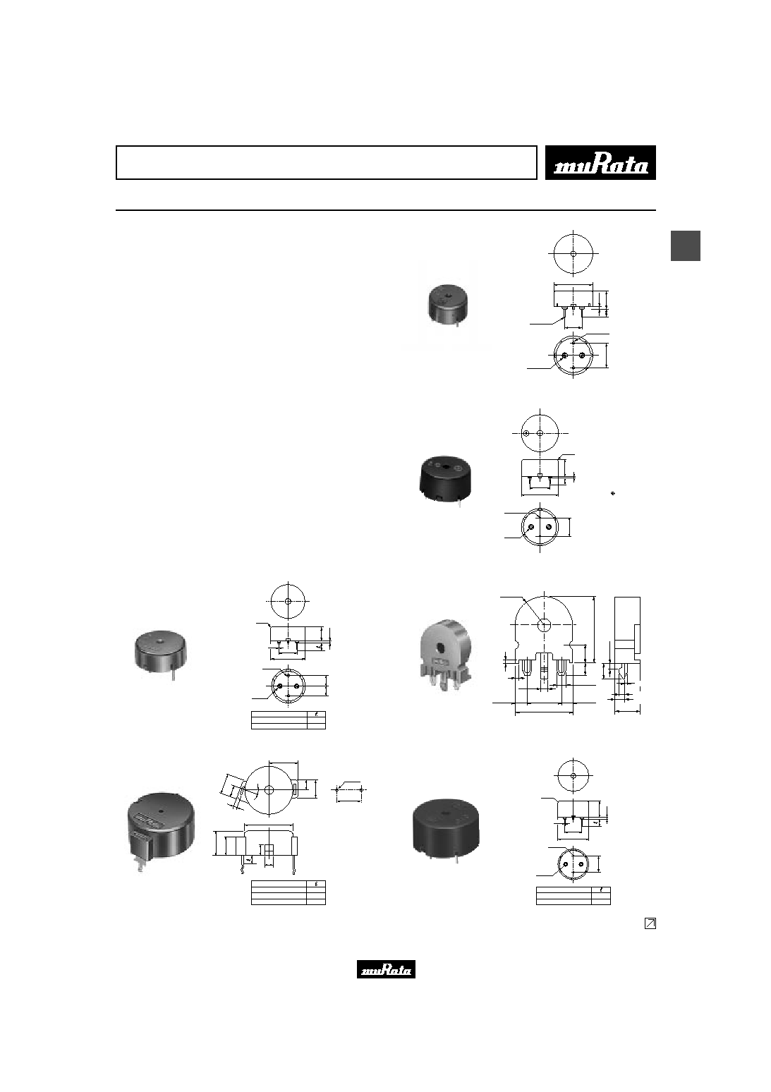
Piezoelectric Sound Components
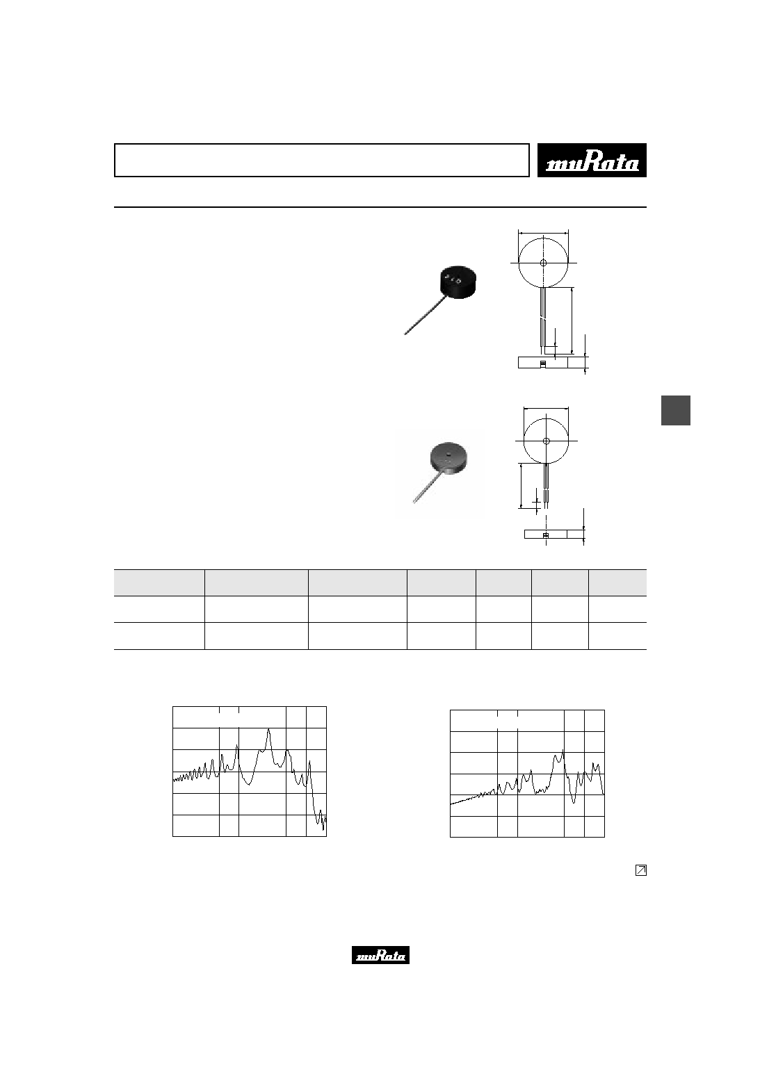
Piezoelectric Sounders External Drive Pin Type
Now microcomputers are widely used for microwave
ovens, air conditioners, cars, toys, timers, and other
alarm equipment. Externally driven piezoelectric
sounders are used in digital watches, electronic
calculators, telephones and other equipment. They are
driven by a signal (ex: 2048Hz or 4096Hz) from an LSI
and provide melodious sound.
s Features
1. Low power consumption
2. No contacts therefore, no noise and highly reliable
s Applications
1. Telephone ringers
2. Various office equipment such as PPCs, printers and
keyboards
3. Various home appliances such as microwave ovens
4. Confirmation sound of various audio equipment
0
.
9
2
-
0.5
2
-
1.0
12.6
6
.
9
7
.
5
3
.
5
5.0
2
-
2.5
(In : mm)
Tol. :
±
0.5
PKM13EPY-4002-B0
R1.0
2-
1.2
2-
3.5
8
.
6
1
1
.
0
3
.
5
1
.
2
10.0
17.0
Terminal of marking
side should be connected
to hot side of D.C.
(in mm)
Tol. :
±
0.5
PKM17EPP-2002-B0
0.8
6
.
0
5
.
0
Part Number
PKM17EPP-4001-B0
PKM17EPP-4002-B0
6.5
3.5
7
.
0
1
.
2
17.0
10.0
R1.0
2-
1.2
2-
3.5
(In : mm)
Tol. :
±
0.5
PKM17EPP-4001-B0
R8.5
17.0
1.0
10.0
±
0.15
3.5
2
0
.
0
0
.
5
2.0
±
0.15
+0.25
-0.1
3.5
+0.25
-0.1
5
.
5
3
.
6
4
.
7
1
.
7
±
0
.
1
1.0
±
0.15
7.5
±
0.2
2.0
±
0.05
3.0
±
0.2
1.8
±
0.15
(In : mm)
Tol. :
±
0.5
PKM17EPT-4001-B0
12.6
Hole Pattern
(Reference)
23.0
2-
1.5
2
0
∞
4
.
7
8
.
0
22.0
4.0
5
.
0
8
.
3
1
1
.
0
4
.8
1
0
.5
1.6
Part Number
PKM22EP-2001
PKM22EP-2002
PKM22EP-2003
4.0
8.0
12.0
(In : mm)
Tol. :
±
0.5
PKM22EP-2001
1
0
.
8
1
.
2
22.0
10.0
R1.0
1
0
.
0
2
-
1.2
2
-
3.5
(In : mm)
Tol. :
±
0.5
Part Number
PKM22EPP-2001-B0
PKM22EPP-2002-B0
6.5
3.5
0.8
PKM22EPP-2001-B0
Continued on the following page.
Please read rating and
!
CAUTION (for storage, operating, rating, soldering, mounting and handling) in this PDF catalog to prevent smoking and/or burning, etc.
This catalog has only typical specifications. Therefore, you are requested to approve our product specifications or to transact the approval sheet for product specificaions before ordering.
!
Note
P37E18.pdf 03.7.18
10
2
!
Note
∑ Please read rating and
!
CAUTION (for storage, operating, rating, soldering, mounting and handling) in this catalog to prevent smoking and/or burning, etc.
∑ This catalog has only typical specifications because there is no space for detailed specifications. Therefore, please approve our product specifications or transact the approval sheet for product specifications before ordering.
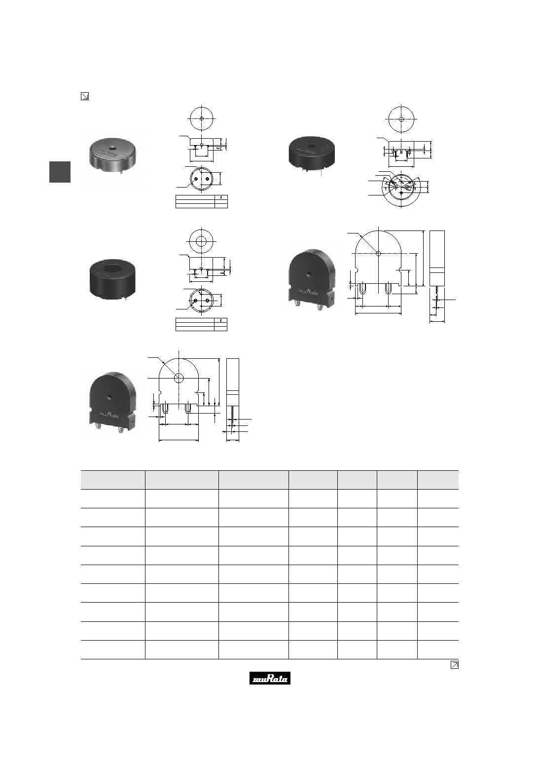
Continued from the preceding page.
7
.
0
1
.
2
22.0
10.0
R1.0
1
0
.
0
2
-
1.2
2
-
3.5
(In : mm)
Tol. :
±
0.5
Part Number
PKM22EPP-4001-B0
PKM22EPP-4002-B0
6.5
3.5
0.8
PKM22EPP-4001-B0
3
-
1.5
10.0
1
8
∞
1
8
∞
12
0∞
12
0∞
1
.
2
8
.
2
6
.
5
3
.
5
R1.0
22.0
0
.
5
3
-
1.7
2
-
3.5
1.2
R8.5
0
.
5
(In : mm)
Tol. :
±
0.5
0.8
PKM22EPP-4005-B0
1
0
.
8
1
.
2
1
0
.
0
22.0
10.0
0.8
R1.0
2-
1.2
2-
3.5
(In : mm)
Tol. :
±
0.5
Part Number
PKM22EPP-4007-B0
PKM22EPP-4012-B0
6.5
3.5
PKM22EPP-4007-B0
1
.
0
7
.
5
1
5
.
5
4
.
0
2
6
.
5
0.8
+
0.1
-
0
R11.0
1.0
3.5
12.5
22.0
7.0
3.0
0.25
6.0
(in mm)
Tol.:
±
0.5
PKM22EPT-2001-B0
R11.0
7
.
5
1
5
.
5
1
.
0
1.0
3.5
12.5
22.0
6.0
7.0
4
.
0
3.0
2
6
.
5
0.25
0.8
+
0.1
-
0
(In : mm)
Tol. :
±
0.5
PKM22EPT-4001-B0
Part Number
Sound
Pressure Level
(dB)
Sound Pressure
Level (Ref. only)
(dB)
Min. of Operating
Voltage Range
Capacitance
(nF)
Operating
Temp. Range
Storage
Temp. Range
PKM13EPY-4002-B0
70 min.
[3Vp-p,4kHz,square wave,10cm]
70 min.
[1Vrms,4kHz,sine wave,10cm]
30 Vp-p max.
5.5
±
30%
[1kHz]
-20 to +70
∞
C
-30 to +80
∞
C
PKM17EPP-2002-B0
70 min.
[3Vo-p,2kHz,square wave,10cm]
70 min.
[1Vrms,2kHz,sine wave,10cm]
25 Vo-p max.
[with polarity]
34
±
30%
[120Hz]
-20 to +70
∞
C
-30 to +80
∞
C
PKM17EPP-4001-B0
72 min.
[3Vp-p,4kHz,square wave,10cm]
72 min.
[1Vrms,4kHz,sine wave,10cm]
25 Vp-p max.
7
±
30%
[1kHz]
-20 to +70
∞
C
-30 to +80
∞
C
PKM17EPT-4001-B0
75 min.
[3Vp-p,4kHz,square wave,10cm]
75 min.
[1Vrms,4kHz,sine wave,10cm]
25 Vp-p max.
9.5
±
30%
[1kHz]
-20 to +70
∞
C
-30 to +80
∞
C
PKM22EP-2001
75 min.
[3Vp-p,2kHz,square wave,10cm]
75 min.
[1Vrms,2kHz,sine wave,10cm]
25 Vp-p max.
17
±
30%
[120Hz]
-20 to +70
∞
C
-30 to +80
∞
C
PKM22EPP-2001-B0
70 min.
[3Vp-p,2kHz,square wave,10cm]
70 min.
[1Vrms,2kHz,sine wave,10cm]
25 Vp-p max.
19
±
30%
[120Hz]
-20 to +70
∞
C
-30 to +80
∞
C
PKM22EPP-4001-B0
75 min.
[3Vp-p,4kHz,square wave,10cm]
75 min.
[1Vrms,4kHz,sine wave,10cm]
25 Vp-p max.
12
±
30%
[1kHz]
-20 to +70
∞
C
-30 to +80
∞
C
PKM22EPP-4005-B0
75 min.
[3Vp-p,4kHz,square wave,10cm]
75 min.
[1Vrms,4kHz,sine wave,10cm]
25 Vp-p max.
12
±
30%
[1kHz]
-20 to +70
∞
C
-30 to +80
∞
C
PKM22EPP-4007-B0
85 min.
[3Vp-p,4kHz,square wave,10cm]
85 min.
[1Vrms,4kHz,sine wave,10cm]
25 Vp-p max.
12
±
30%
[1kHz]
-20 to +70
∞
C
-30 to +80
∞
C
Continued on the following page.
Please read rating and
!
CAUTION (for storage, operating, rating, soldering, mounting and handling) in this PDF catalog to prevent smoking and/or burning, etc.
This catalog has only typical specifications. Therefore, you are requested to approve our product specifications or to transact the approval sheet for product specificaions before ordering.
!
Note
P37E18.pdf 03.7.18
11
2
!
Note
∑ Please read rating and
!
CAUTION (for storage, operating, rating, soldering, mounting and handling) in this catalog to prevent smoking and/or burning, etc.
∑ This catalog has only typical specifications because there is no space for detailed specifications. Therefore, please approve our product specifications or transact the approval sheet for product specifications before ordering.
Part Number
Sound
Pressure Level
(dB)
Sound Pressure
Level (Ref. only)
(dB)
Min. of Operating
Voltage Range
Capacitance
(nF)
Operating
Temp. Range
Storage
Temp. Range
Continued from the preceding page.
PKM22EPT-2001-B0
70 min.
[3Vp-p,2kHz,square wave,10cm]
70 min.
[1Vrms,2kHz,sine wave,10cm]
25 Vp-p max.
19
±
30%
[120Hz]
-20 to +70
∞
C
-30 to +80
∞
C
PKM22EPT-4001-B0
85 min.
[3Vp-p,4kHz,square wave,10cm]
85 min.
[1Vrms,4kHz,sine wave,10cm]
25 Vp-p max.
10
±
30%
[1kHz]
-20 to +70
∞
C
-30 to +80
∞
C
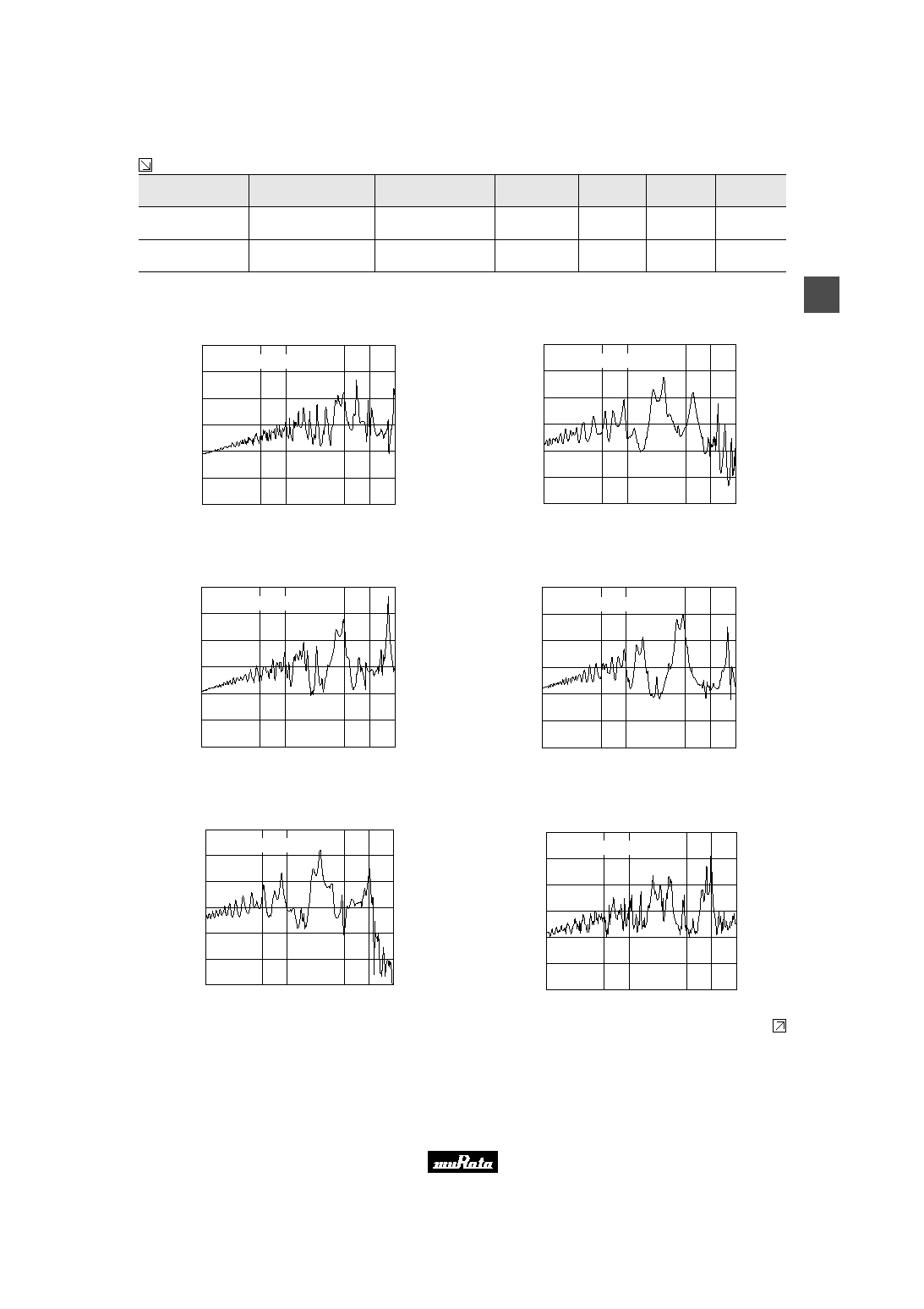
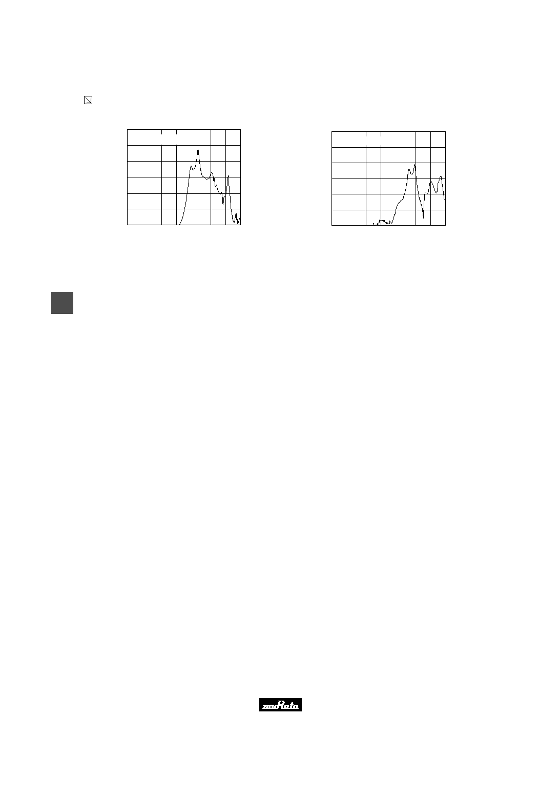
s Freq. Response (Square Wave 3Vp-p, 10cm)
PKM13EPY-4002-B0
S
o
u
n
d
P
r
e
s
s
u
r
e
L
e
v
e
l
(
d
B
)
40
50
Frequency (Hz)
100
500
1k
5k
10k
20k
60
70
80
90
100
Input Voltage : 3.00 Vp-p Square
Distance : 10cm
PKM17EPP-2002-B0
S
o
u
n
d
P
r
e
s
s
u
r
e
L
e
v
e
l
(
d
B
)
40
50
Frequency (Hz)
100
500
1k
5k
10k
20k
60
70
80
90
100
Input Voltage : 3.00 Vp-p Square
Distance : 10cm
PKM17EPP-4001-B0
S
o
u
n
d
P
r
e
s
s
u
r
e
L
e
v
e
l
(
d
B
)
40
50
Frequency (Hz)
100
500
1k
5k
10k
20k
60
70
80
90
100
Input Voltage : 3.00 Vp-p Square
Distance : 10cm
PKM17EPT-4001-B0
S
o
u
n
d
P
r
e
s
s
u
r
e
L
e
v
e
l
(
d
B
)
40
50
Frequency (Hz)
100
500
1k
5k
10k
20k
60
70
80
90
100
Input Voltage : 3.00 Vp-p Square
Distance : 10cm
PKM22EP-2001
S
o
u
n
d
P
r
e
s
s
u
r
e
L
e
v
e
l
(
d
B
)
40
50
Frequency (Hz)
100
500
1k
5k
10k
20k
60
70
80
90
100
Input Voltage : 3.00 Vp-p Square
Distance : 10cm
PKM22EPP-2001-B0
S
o
u
n
d
P
r
e
s
s
u
r
e
L
e
v
e
l
(
d
B
)
40
50
Frequency (Hz)
100
500
1k
5k
10k
20k
60
70
80
90
100
Input Voltage : 3.00 Vp-p Square
Distance : 10cm
Continued on the following page.
Please read rating and
!
CAUTION (for storage, operating, rating, soldering, mounting and handling) in this PDF catalog to prevent smoking and/or burning, etc.
This catalog has only typical specifications. Therefore, you are requested to approve our product specifications or to transact the approval sheet for product specificaions before ordering.
!
Note
P37E18.pdf 03.7.18
12
2
!
Note
∑ Please read rating and
!
CAUTION (for storage, operating, rating, soldering, mounting and handling) in this catalog to prevent smoking and/or burning, etc.
∑ This catalog has only typical specifications because there is no space for detailed specifications. Therefore, please approve our product specifications or transact the approval sheet for product specifications before ordering.
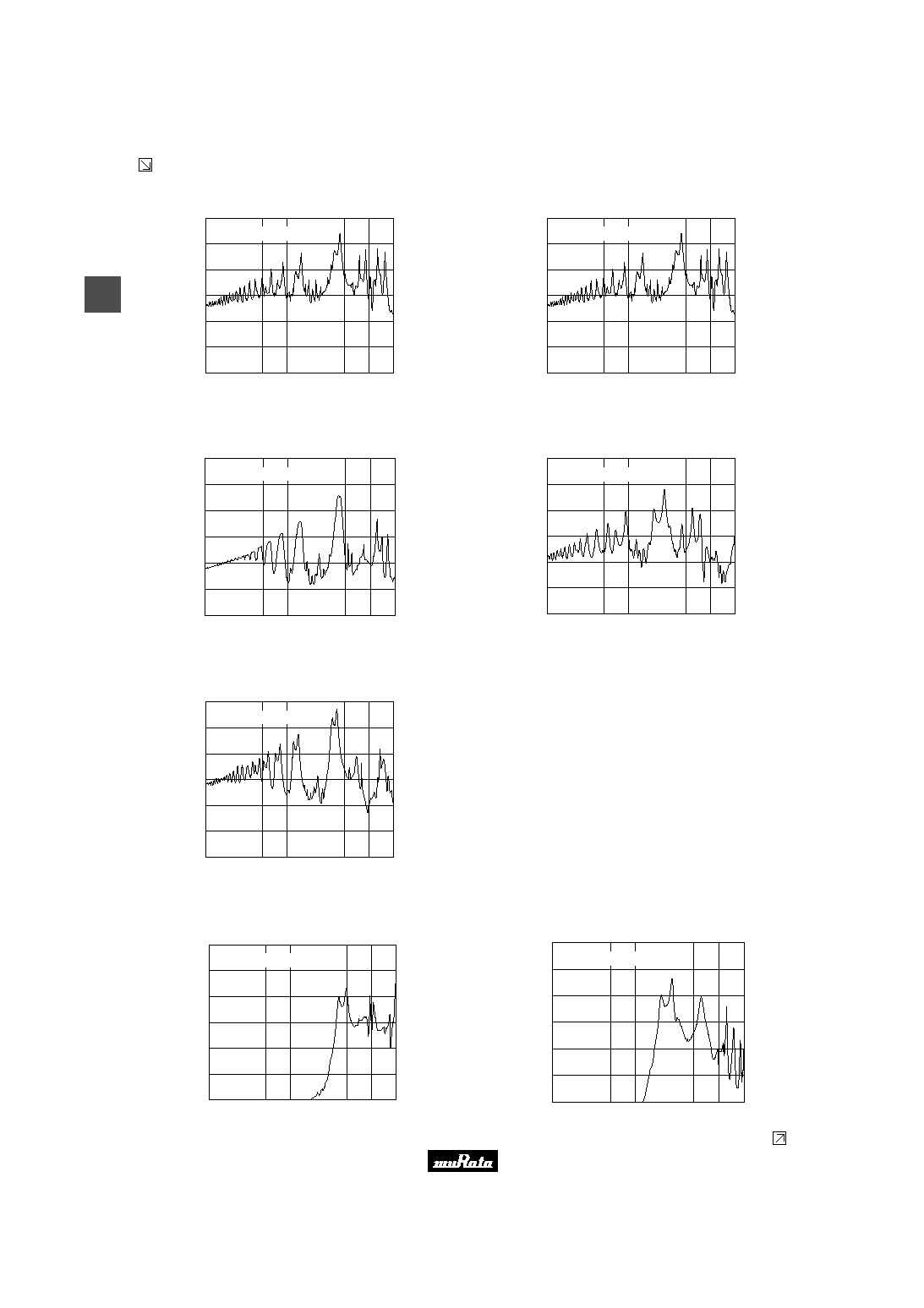
Continued from the preceding page.
s Freq. Response (Square Wave 3Vp-p, 10cm)
PKM22EPP-4001-B0
S
o
u
n
d
P
r
e
s
s
u
r
e
L
e
v
e
l
(
d
B
)
40
50
Frequency (Hz)
100
500
1k
5k
10k
20k
60
70
80
90
100
Input Voltage : 3.00 Vp-p Square
Distance : 10cm
PKM22EPP-4005-B0
S
o
u
n
d
P
r
e
s
s
u
r
e
L
e
v
e
l
(
d
B
)
40
50
Frequency (Hz)
100
500
1k
5k
10k
20k
60
70
80
90
100
Input Voltage : 3.00 Vp-p Square
Distance : 10cm
PKM22EPP-4007-B0
S
o
u
n
d
P
r
e
s
s
u
r
e
L
e
v
e
l
(
d
B
)
50
60
Frequency (Hz)
100
500
1k
5k
10k
20k
70
80
90
100
110
Input Voltage : 3.00 Vp-p Square
Distance : 10cm
PKM22EPT-2001-B0
S
o
u
n
d
P
r
e
s
s
u
r
e
L
e
v
e
l
(
d
B
)
40
50
Frequency (Hz)
100
500
1k
5k
10k
20k
60
70
80
90
100
Input Voltage : 3.00 Vp-p Square
Distance : 10cm
PKM22EPT-4001-B0
S
o
u
n
d
P
r
e
s
s
u
r
e
L
e
v
e
l
(
d
B
)
40
50
Frequency (Hz)
100
500
1k
5k
10k
20k
60
70
80
90
100
Input Voltage : 3.00 Vp-p Square
Distance : 10cm
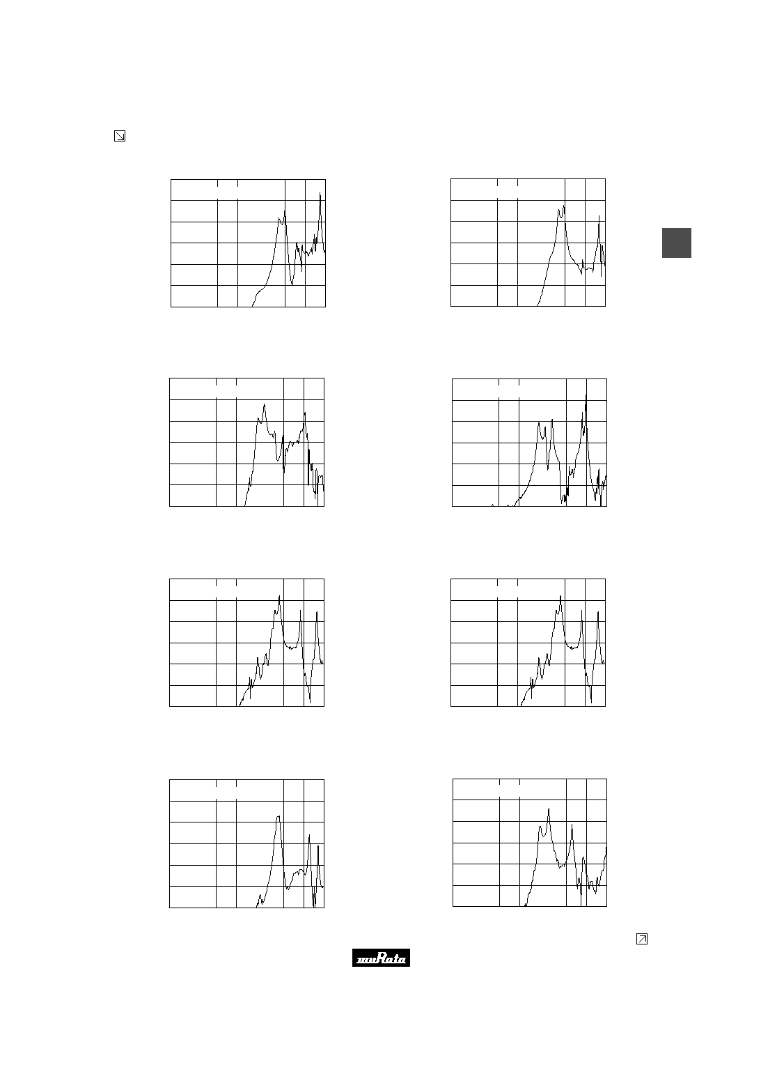
s Freq. Response (Sine Wave 1Vrms, 10cm)
PKM13EPY-4002-B0
S
o
u
n
d
P
r
e
s
s
u
r
e
L
e
v
e
l
(
d
B
)
40
50
Frequency (Hz)
100
500
1k
5k
10k
20k
60
70
80
90
100
Input Voltage : 1.00 Vrms Sine
Distance : 10cm
PKM17EPP-2002-B0
S
o
u
n
d
P
r
e
s
s
u
r
e
L
e
v
e
l
(
d
B
)
40
50
Frequency (Hz)
100
500
1k
5k
10k
20k
60
70
80
90
100
Input Voltage : 1.00 Vrms Sine
Distance : 10cm
Continued on the following page.
Please read rating and
!
CAUTION (for storage, operating, rating, soldering, mounting and handling) in this PDF catalog to prevent smoking and/or burning, etc.
This catalog has only typical specifications. Therefore, you are requested to approve our product specifications or to transact the approval sheet for product specificaions before ordering.
!
Note
P37E18.pdf 03.7.18
13
2
!
Note
∑ Please read rating and
!
CAUTION (for storage, operating, rating, soldering, mounting and handling) in this catalog to prevent smoking and/or burning, etc.
∑ This catalog has only typical specifications because there is no space for detailed specifications. Therefore, please approve our product specifications or transact the approval sheet for product specifications before ordering.
Continued from the preceding page.
s Freq. Response (Sine Wave 1Vrms, 10cm)
PKM17EPP-4001-B0
S
o
u
n
d
P
r
e
s
s
u
r
e
L
e
v
e
l
(
d
B
)
40
50
Frequency (Hz)
100
500
1k
5k
10k
20k
60
70
80
90
100
Input Voltage : 1.00 Vrms Sine
Distance : 10cm
PKM17EPT-4001-B0
S
o
u
n
d
P
r
e
s
s
u
r
e
L
e
v
e
l
(
d
B
)
40
50
Frequency (Hz)
100
500
1k
5k
10k
20k
60
70
80
90
100
Input Voltage : 1.00 Vrms Sine
Distance : 10cm
PKM22EP-2001
S
o
u
n
d
P
r
e
s
s
u
r
e
L
e
v
e
l
(
d
B
)
40
50
Frequency (Hz)
100
500
1k
5k
10k
20k
60
70
80
90
100
Input Voltage : 1.00 Vrms Sine
Distance : 10cm
PKM22EPP-2001-B0
S
o
u
n
d
P
r
e
s
s
u
r
e
L
e
v
e
l
(
d
B
)
40
50
Frequency (Hz)
100
500
1k
5k
10k
20k
60
70
80
90
100
Input Voltage : 1.00 Vrms Sine
Distance : 10cm
PKM22EPP-4001-B0
S
o
u
n
d
P
r
e
s
s
u
r
e
L
e
v
e
l
(
d
B
)
40
50
Frequency (Hz)
100
500
1k
5k
10k
20k
60
70
80
90
100
Input Voltage : 1.00 Vrms Sine
Distance : 10cm
PKM22EPP-4005-B0
S
o
u
n
d
P
r
e
s
s
u
r
e
L
e
v
e
l
(
d
B
)
40
50
Frequency (Hz)
100
500
1k
5k
10k
20k
60
70
80
90
100
Input Voltage : 1.00 Vrms Sine
Distance : 10cm
PKM22EPP-4007-B0
S
o
u
n
d
P
r
e
s
s
u
r
e
L
e
v
e
l
(
d
B
)
50
60
Frequency (Hz)
100
500
1k
5k
10k
20k
70
80
90
100
110
Input Voltage : 1.00 Vrms Sine
Distance : 10cm
PKM22EPT-2001-B0
S
o
u
n
d
P
r
e
s
s
u
r
e
L
e
v
e
l
(
d
B
)
40
50
Frequency (Hz)
100
500
1k
5k
10k
20k
60
70
80
90
100
Input Voltage : 1.00 Vrms Sine
Distance : 10cm
Continued on the following page.
Please read rating and
!
CAUTION (for storage, operating, rating, soldering, mounting and handling) in this PDF catalog to prevent smoking and/or burning, etc.
This catalog has only typical specifications. Therefore, you are requested to approve our product specifications or to transact the approval sheet for product specificaions before ordering.
!
Note
P37E18.pdf 03.7.18
14
2
!
Note
∑ Please read rating and
!
CAUTION (for storage, operating, rating, soldering, mounting and handling) in this catalog to prevent smoking and/or burning, etc.
∑ This catalog has only typical specifications because there is no space for detailed specifications. Therefore, please approve our product specifications or transact the approval sheet for product specifications before ordering.
Continued from the preceding page.
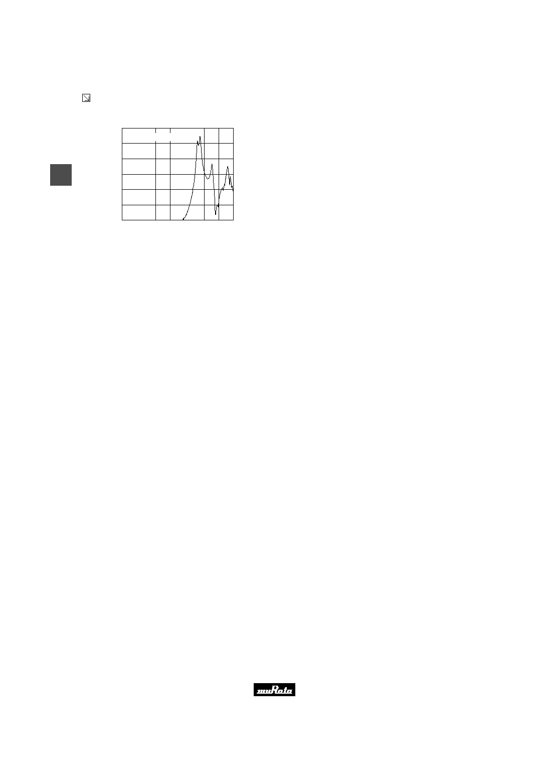
s Freq. Response (Sine Wave 1Vrms, 10cm)
PKM22EPT-4001-B0
S
o
u
n
d
P
r
e
s
s
u
r
e
L
e
v
e
l
(
d
B
)
40
50
Frequency (Hz)
100
500
1k
5k
10k
20k
60
70
80
90
100
Input Voltage : 1.00 Vrms Sine
Distance : 10cm
Please read rating and
!
CAUTION (for storage, operating, rating, soldering, mounting and handling) in this PDF catalog to prevent smoking and/or burning, etc.
This catalog has only typical specifications. Therefore, you are requested to approve our product specifications or to transact the approval sheet for product specificaions before ordering.
!
Note
P37E18.pdf 03.7.18
15
3
!
Note
∑ Please read rating and
!
CAUTION (for storage, operating, rating, soldering, mounting and handling) in this catalog to prevent smoking and/or burning, etc.
∑ This catalog has only typical specifications because there is no space for detailed specifications. Therefore, please approve our product specifications or transact the approval sheet for product specifications before ordering.
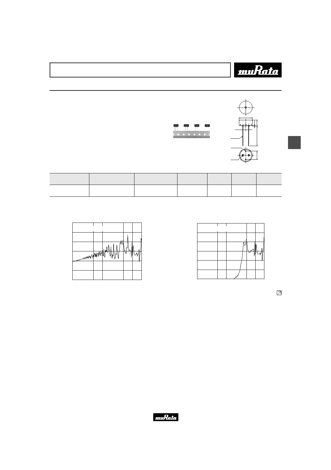
Piezoelectric Sound Components
Piezoelectric Sounders External Drive Pin Type Taping
Taking advantage of extensive automatic insertion
design technology and materials experience, Murata
has developed standard taping type piezoelectric
sounder.
This Murata technology supports labor and cost saving
activities.
s Features
1. High and stable mountability
2. Ammo packaging
3. Minimum quantity (order in sets only): 500 pcs.
0
.
9
2
-
0.5
2
-
1.0
12.6
6
.
9
7
.
5
2
2
.
0
5.0
2
-
2.5
(In : mm)
Tol. :
±
0.5
Part Number
Sound
Pressure Level
(dB)
Sound Pressure
Level (Ref. only)
(dB)
Min. of Operating
Voltage Range
Capacitance
(nF)
Operating
Temp. Range
Storage
Temp. Range
PKM13EPY-4000-A0
70 min.
[3Vp-p,4kHz,square wave,10cm]
70 min.
[1Vrms,4kHz,sine wave,10cm]
30 Vp-p max.
5.5
±
30%
[1kHz]
-20 to +70
∞
C
-30 to +80
∞
C
s Freq. Response (Square Wave 3Vp-p, 10cm)
S
o
u
n
d
P
r
e
s
s
u
r
e
L
e
v
e
l
(
d
B
)
40
50
Frequency (Hz)
100
500
1k
5k
10k
20k
60
70
80
90
100
Input Voltage : 3.00 Vp-p Square
Distance : 10cm
s Freq. Response (Sine Wave 1Vrms, 10cm)
S
o
u
n
d
P
r
e
s
s
u
r
e
L
e
v
e
l
(
d
B
)
40
50
Frequency (Hz)
100
500
1k
5k
10k
20k
60
70
80
90
100
Input Voltage : 1.00 Vrms Sine
Distance : 10cm
Continued on the following page.
Please read rating and
!
CAUTION (for storage, operating, rating, soldering, mounting and handling) in this PDF catalog to prevent smoking and/or burning, etc.
This catalog has only typical specifications. Therefore, you are requested to approve our product specifications or to transact the approval sheet for product specificaions before ordering.
!
Note
P37E18.pdf 03.7.18
16
3
!
Note
∑ Please read rating and
!
CAUTION (for storage, operating, rating, soldering, mounting and handling) in this catalog to prevent smoking and/or burning, etc.
∑ This catalog has only typical specifications because there is no space for detailed specifications. Therefore, please approve our product specifications or transact the approval sheet for product specifications before ordering.
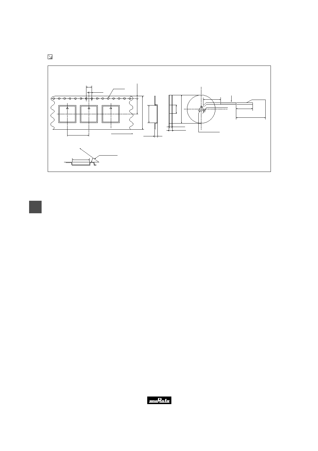
Continued from the preceding page.
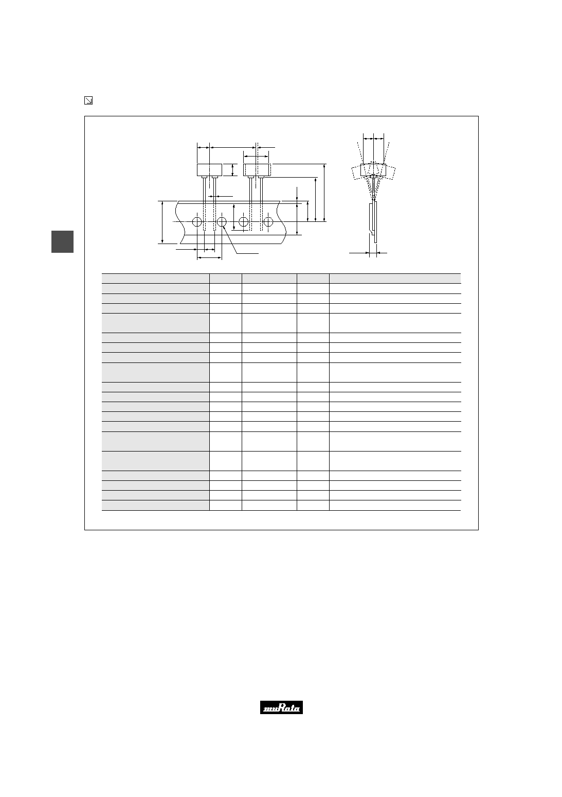
s Taping Dimension
Item
Width of diameter
Height of component
Dimensions of terminal
Lead length under the
hold down tape
Pitch of component
Pitch of sprocket
Length from hole center to lead
Length from hole center to
component center
Lead spacing
Slant to the forward or backward
Width of carrier tape
Width of hold down tape
Position of sprocket hole
Gap of hold down tape and
carrier tape
Distance between the center of
sprocket hole and lead stopper
Total height of component
Diameter of sprocket hole
Total thickness of tape
Body tilt
D
A
d
1
L
1
P
P
0
P
1
P
2
F
dh
W
W
0
W
1
W
2
H
0
H
1
D
0
t
dS
(in mm)
Code
±
0.5
±
0.5
±
0.1
--
±
0.5
±
0.2
±
0.7
±
0.7
±
0.5
±
1.0
±
0.5
--
±
0.5
--
±
0.5
--
±
0.2
±
0.2
±
1.0
Tol.
Tolerance for Pitches 10
Z
P
0
=127
±
2mm
360
∞
: 1mm max.
Hold down tape does not exceed the carrier tape.
Remarks
¯12.6
6.9
¯0.5
8.0 min.
25.4
12.7
3.85
6.35
5.0
0
18.0
12.5 min.
9.0
2.0 max.
18.0
26.0 max.
¯4.0
0.6
0
Nominal Value
H
1
H
0
W
1
P
P
2
dh dh
t
P
0
D
0
P
1
F
d
1
dS
A
L
1
D
W
0
W
W
2
Please read rating and
!
CAUTION (for storage, operating, rating, soldering, mounting and handling) in this PDF catalog to prevent smoking and/or burning, etc.
This catalog has only typical specifications. Therefore, you are requested to approve our product specifications or to transact the approval sheet for product specificaions before ordering.
!
Note
P37E18.pdf 03.7.18
17
4
!
Note
∑ Please read rating and
!
CAUTION (for storage, operating, rating, soldering, mounting and handling) in this catalog to prevent smoking and/or burning, etc.
∑ This catalog has only typical specifications because there is no space for detailed specifications. Therefore, please approve our product specifications or transact the approval sheet for product specifications before ordering.
Piezoelectric Sound Components
Piezoelectric Sounders External Drive Lead Wire Type
Now microcomputers are widely used for microwave
ovens, air conditioners, cars, toys, timers, and other
alarm equipment. Externally driven piezoelectric
sounders are used in digital watches, electronic
calculators, telephones and other equipment. They are
driven by a signal (ex: 2048Hz or 4096Hz) from an LSI
and provide melodious sound.
s Features
1. Low power consumption
2. No contacts therefore, no noise and highly reliable
s Applications
1. Telephone ringers
2. Various office equipment such as PPCs, printers and
keyboards
3. Various home appliances such as microwave ovens
4. Confirmation sound of various audio equipment
7
0
±
5
3
±
1
16.8
(In : mm)
Tol. :
±
0.5
7
.
0
+
0
≠
0
.
3
PKM17EW-2001
16.8
±
0.2
1
0
0
±
1
0
4
.
0
+
0
≠
0
.
3
(In : mm)
5
±
2
PKM17EW-4000
Part Number
Sound
Pressure Level
(dB)
Sound Pressure
Level (Ref. only)
(dB)
Min. of Operating
Voltage Range
Capacitance
(nF)
Operating
Temp. Range
Storage
Temp. Range
PKM17EW-2001
72 min.
[3Vp-p,2kHz,square wave,10cm]
70 min.
[1Vrms,2kHz,sine wave,10cm]
7 Vp-p max.
40
±
30%
[120Hz]
-20 to +70
∞
C
-30 to +80
∞
C
PKM17EW-4000
75 min.
[3Vp-p,4kHz,square wave,10cm]
70 min.
[1Vrms,4kHz,sine wave,10cm]
25 Vp-p max.
9.5
±
30%
[1kHz]
-20 to +70
∞
C
-30 to +80
∞
C
s Freq. Response (Square Wave 3Vp-p, 10cm)
PKM17EW-2001
100
500
1k
5k
10k
20k
50
40
60
70
80
90
100
Frequency (Hz)
S
o
u
n
d
P
r
e
s
s
u
r
e
L
e
v
e
l
(
d
B
)
Input Voltage : 3.00 Vp-p Square
Distance : 10 cm
PKM17EW-4000
S
o
u
n
d
P
r
e
s
s
u
r
e
L
e
v
e
l
(
d
B
)
40
50
Frequency (Hz)
100
500
1k
5k
10k
20k
60
70
80
90
100
Input Voltage : 3.00 Vp-p Square
Distance : 10cm
Continued on the following page.
Please read rating and
!
CAUTION (for storage, operating, rating, soldering, mounting and handling) in this PDF catalog to prevent smoking and/or burning, etc.
This catalog has only typical specifications. Therefore, you are requested to approve our product specifications or to transact the approval sheet for product specificaions before ordering.
!
Note
P37E18.pdf 03.7.18
18
4
!
Note
∑ Please read rating and
!
CAUTION (for storage, operating, rating, soldering, mounting and handling) in this catalog to prevent smoking and/or burning, etc.
∑ This catalog has only typical specifications because there is no space for detailed specifications. Therefore, please approve our product specifications or transact the approval sheet for product specifications before ordering.
Continued from the preceding page.
s Freq. Response (Sine Wave 1Vrms, 10cm)
PKM17EW-2001
100
500
1k
5k
10k
20k
50
40
60
70
80
90
100
Frequency (Hz)
S
o
u
n
d
P
r
e
s
s
u
r
e
L
e
v
e
l
(
d
B
)
IInput Voltage : 1.00 Vrms Sine
Distance : 10 cm
PKM17EW-4000
S
o
u
n
d
P
r
e
s
s
u
r
e
L
e
v
e
l
(
d
B
)
40
50
Frequency (Hz)
100
500
1k
5k
10k
20k
60
70
80
90
100
Input Voltage : 1.00 Vrms Sine
Distance : 10cm
Please read rating and
!
CAUTION (for storage, operating, rating, soldering, mounting and handling) in this PDF catalog to prevent smoking and/or burning, etc.
This catalog has only typical specifications. Therefore, you are requested to approve our product specifications or to transact the approval sheet for product specificaions before ordering.
!
Note
P37E18.pdf 03.7.18
19
5
!
Note
∑ Please read rating and
!
CAUTION (for storage, operating, rating, soldering, mounting and handling) in this catalog to prevent smoking and/or burning, etc.
∑ This catalog has only typical specifications because there is no space for detailed specifications. Therefore, please approve our product specifications or transact the approval sheet for product specifications before ordering.
Piezoelectric Sound Components
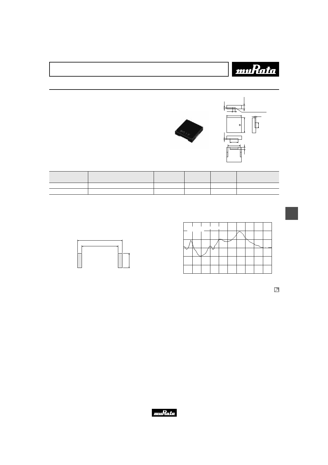
Piezoelectric Sounders External Drive SMD Type
Taking advantage of extensive acoustic and mechanical
design technology and high performance ceramics,
Murata has developed SMD piezoelectric sounders that
suite the thin, high-density design of electronic
equipment.
s Features
1. High S.P.L. and clear sound
2. Reflowable
3. Tape & Reel supply
4. Minimum quantity (order in sets only): 1,000 pcs.
3
.
0
m
a
x
.
0.9
4
.
0
(
0
.
7
)
(6.4)
10.0
(
2
.
1
)
12.0
1
2
.
0
(1.9)
(
0
.
9
)
Sound Emitting Hole
in mm
( ) : Ref. only
Tol.
±
0.2
Part Number
Sound Pressure Level
(dB)
Max. of Operating
Voltage Range
(Vp-p)
Operating
Temp. Range
Storage
Temp. Range
Use
PKLCS1212E4001-R1
75 min.[3Vp-p,4kHz,square wave,10cm]
25 max.
-20 to +70
∞
C
-30 to +80
∞
C
For consumer electronics
PKLCS1212E40A1-R1
75 min.[3Vp-p,4kHz,square wave,10cm]
25 max.
-40 to +85
∞
C
-40 to +85
∞
C
For automotive electronics
s Standard Land Pattern Dimensions
10.0
12.4
4
.
0
(in mm)
s Freq. Response (Square Wave 3Vp-p, 10cm)
Frequency (kHz)
100
90
80
70
60
50
40
1.0
1.5
2.0
2.5
3.0
3.5
4.0
4.5
5.0
5.5
6.0
S
o
u
n
d
P
r
e
s
s
u
r
e
L
e
v
e
l
(
d
B
)
Input Voltage : 3.00Vp-p Square
Distance : 10cm
Continued on the following page.
Please read rating and
!
CAUTION (for storage, operating, rating, soldering, mounting and handling) in this PDF catalog to prevent smoking and/or burning, etc.
This catalog has only typical specifications. Therefore, you are requested to approve our product specifications or to transact the approval sheet for product specificaions before ordering.
!
Note
P37E18.pdf 03.7.18
20
5
!
Note
∑ Please read rating and
!
CAUTION (for storage, operating, rating, soldering, mounting and handling) in this catalog to prevent smoking and/or burning, etc.
∑ This catalog has only typical specifications because there is no space for detailed specifications. Therefore, please approve our product specifications or transact the approval sheet for product specifications before ordering.
Continued from the preceding page.
s Taping Dimension
Dimensions of Carrier Tape
Dimensions of Reel
(in mm)
+0.1
2
4
.
0
±
0
.
2
1
1
.
5
±
0
.
1
1
.
7
5
±
0
.
1
¯1.50
2.0
±
0.1
4.0
±
0.1
16.0
±
0.1
1
2
.
5
±
0
.
1
3.1
±
0.1
Direction of Feed
-0.0
12.5
±
0.1
Cover Film
The cover Film peel strength force 0.1~0.7N
The cover Film peel speed 300mm/min.
10
∞
13.0
±
0.2
33.5max.
(
¯
3
3
0
)
160~200
240~280
2.2
±
0.2
Components
Trailer
Empty
Leader
(
¯
8
0
)
400~560
25.5
±
0.5
Cover Film
Please read rating and
!
CAUTION (for storage, operating, rating, soldering, mounting and handling) in this PDF catalog to prevent smoking and/or burning, etc.
This catalog has only typical specifications. Therefore, you are requested to approve our product specifications or to transact the approval sheet for product specificaions before ordering.
!
Note
P37E18.pdf 03.7.18
Piezoelectric Sounders (External Drive) Circuit/Notice
21
5
!
Note
∑ Please read rating and
!
CAUTION (for storage, operating, rating, soldering, mounting and handling) in this catalog to prevent smoking and/or burning, etc.
∑ This catalog has only typical specifications because there is no space for detailed specifications. Therefore, please approve our product specifications or transact the approval sheet for product specifications before ordering.
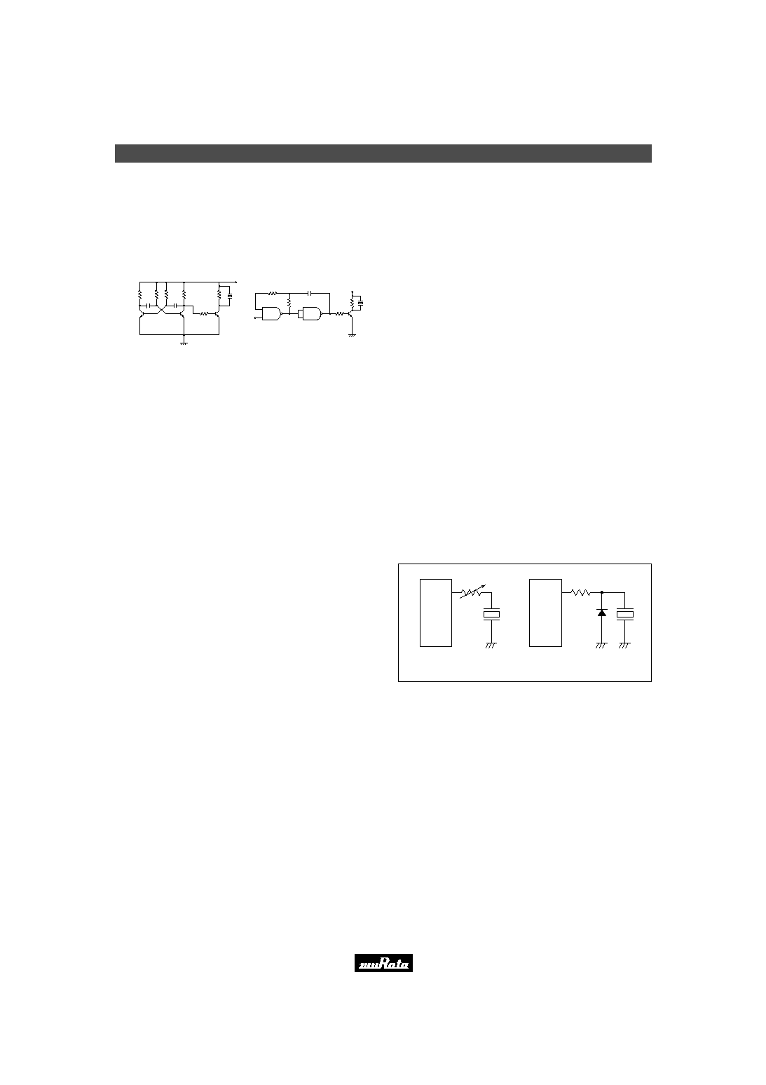
s Circuit
510
20k
20k
510
1k
+V
1k
0.01
µ
F
0.01
µ
F
+V
1k
1k
120k
1M
Input
0.001
µ
F
The following are examples of externally driven circuits.
(1) Unstable multi-vibrator using Tr.
(2) Circuits using inverters or NAND gates.
(1)
(2)
s Notice (Soldering and Mounting)
Washing of the component is not acceptable, because
it is not sealed.
s Notice (Handling)
1. The component may be damaged if mechanical stress
exceeding specifications is applied.
2. Take care to protect operating circuit from surge voltage
resulting from excessive force, falling, shock or
temperature change.
3. If DC voltage is applied to the component, silver migration
may occur. Please pay full attention to avoid subjecting
the component to DC voltage for long periods.
4. The resistor should be used as shown in Fig. A.
A suitable resistance value should be chosen, preferably
1k
to 2k
. Instead of this measure, a diode may also be
applied as shown in Fig. B.
5. Avoid excessive pulling of lead wire because wire may
break or soldering point may come off.
IC
Fig. A
IC
Fig. B
R
Please read rating and
!
CAUTION (for storage, operating, rating, soldering, mounting and handling) in this PDF catalog to prevent smoking and/or burning, etc.
This catalog has only typical specifications. Therefore, you are requested to approve our product specifications or to transact the approval sheet for product specificaions before ordering.
!
Note
P37E18.pdf 03.7.18