29
5
!
Note
∑ Please read rating and
!
CAUTION (for storage and operating, rating, soldering and mounting, handling) in this catalog to prevent smoking and/or burning, etc.
∑ This catalog has only typical specifications because there is no space for detailed specifications. Therefore, please approve our product specification or transact the approval sheet for product specification before ordering.
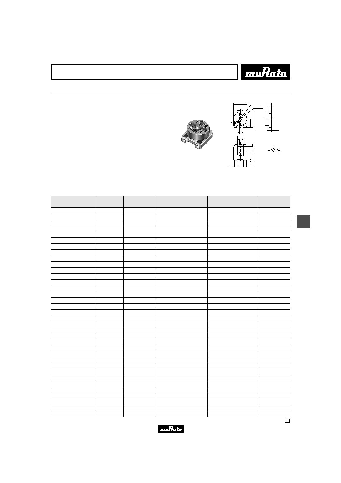
Trimmer Potentiometers
SMD Sealed Type 4mm Size PVM4 Series
s Fetures
1. Available for flow and reflow soldering method
while maintaining unique sealed construction.
2. Simple construction by 3 piece parts achieve high
reliability.
3. Available for cleaning after soldering.
4. Plated termination achieve a high resistance to
solder leaching.
5. High grade version is available (PVM4AxxxB01).
s Applications
1. FDDs 2. HDDs
3. Measuring equipments 4. Encorders
5. Professional use cameras
#2
#1
#3
CLOCKWISE
#1
#2
#3
4.0
2
.
7
Ī
0
.
1
(
2
.
4
)
4
.
7
2.0
Ī
0.2
0.7
0.75
0.55
Ī
0.1
0.6
0
.
8
1
.
5
2
.
4
(
0
.
3
)
0.85
1.8
0.85
0.35
Ī
0.1 Depth
1.7
3.8 Dia.
1.5 Dia.
in mm
(
Tolerance :
Ī
0.3
)
Part Number
Power Rating
(W)
Soldering Method
Number of Turns
(Effective Rotation Angle)
Total Resistance Value
TCR
(ppm/
į
C)
PVM4A101A01
0.1(70
į
C)
Flow/Reflow
1(240
įĪ
10
į
)
100ohm
Ī
25%
Ī
250
PVM4A201A01
0.1(70
į
C)
Flow/Reflow
1(240
įĪ
10
į
)
200ohm
Ī
25%
Ī
250
PVM4A301A01
0.1(70
į
C)
Flow/Reflow
1(240
įĪ
10
į
)
300ohm
Ī
25%
Ī
250
PVM4A501A01
0.1(70
į
C)
Flow/Reflow
1(240
įĪ
10
į
)
500ohm
Ī
25%
Ī
250
PVM4A102A01
0.1(70
į
C)
Flow/Reflow
1(240
įĪ
10
į
)
1k ohm
Ī
25%
Ī
250
PVM4A202A01
0.1(70
į
C)
Flow/Reflow
1(240
įĪ
10
į
)
2k ohm
Ī
25%
Ī
250
PVM4A302A01
0.1(70
į
C)
Flow/Reflow
1(240
įĪ
10
į
)
3k ohm
Ī
25%
Ī
250
PVM4A502A01
0.1(70
į
C)
Flow/Reflow
1(240
įĪ
10
į
)
5k ohm
Ī
25%
Ī
250
PVM4A103A01
0.1(70
į
C)
Flow/Reflow
1(240
įĪ
10
į
)
10k ohm
Ī
25%
Ī
250
PVM4A203A01
0.1(70
į
C)
Flow/Reflow
1(240
įĪ
10
į
)
20k ohm
Ī
25%
Ī
250
PVM4A303A01
0.1(70
į
C)
Flow/Reflow
1(240
įĪ
10
į
)
30k ohm
Ī
25%
Ī
250
PVM4A503A01
0.1(70
į
C)
Flow/Reflow
1(240
įĪ
10
į
)
50k ohm
Ī
25%
Ī
250
PVM4A104A01
0.1(70
į
C)
Flow/Reflow
1(240
įĪ
10
į
)
100k ohm
Ī
25%
Ī
250
PVM4A204A01
0.1(70
į
C)
Flow/Reflow
1(240
įĪ
10
į
)
200k ohm
Ī
25%
Ī
250
PVM4A304A01
0.1(70
į
C)
Flow/Reflow
1(240
įĪ
10
į
)
300k ohm
Ī
25%
Ī
250
PVM4A504A01
0.1(70
į
C)
Flow/Reflow
1(240
įĪ
10
į
)
500k ohm
Ī
25%
Ī
250
PVM4A105A01
0.1(70
į
C)
Flow/Reflow
1(240
įĪ
10
į
)
1M ohm
Ī
25%
Ī
250
PVM4A205A01
0.1(70
į
C)
Flow/Reflow
1(240
įĪ
10
į
)
2M ohm
Ī
25%
Ī
250
PVM4A101B01
0.25(70
į
C)
Flow/Reflow
1(240
įĪ
10
į
)
100ohm
Ī
20%
Ī
150
PVM4A201B01
0.25(70
į
C)
Flow/Reflow
1(240
įĪ
10
į
)
200ohm
Ī
20%
Ī
100
PVM4A301B01
0.25(70
į
C)
Flow/Reflow
1(240
įĪ
10
į
)
300ohm
Ī
20%
Ī
100
PVM4A501B01
0.25(70
į
C)
Flow/Reflow
1(240
įĪ
10
į
)
500ohm
Ī
20%
Ī
100
PVM4A102B01
0.25(70
į
C)
Flow/Reflow
1(240
įĪ
10
į
)
1k ohm
Ī
20%
Ī
100
PVM4A202B01
0.25(70
į
C)
Flow/Reflow
1(240
įĪ
10
į
)
2k ohm
Ī
20%
Ī
100
PVM4A302B01
0.25(70
į
C)
Flow/Reflow
1(240
įĪ
10
į
)
3k ohm
Ī
20%
Ī
100
PVM4A502B01
0.25(70
į
C)
Flow/Reflow
1(240
įĪ
10
į
)
5k ohm
Ī
20%
Ī
100
PVM4A103B01
0.25(70
į
C)
Flow/Reflow
1(240
įĪ
10
į
)
10k ohm
Ī
20%
Ī
100
PVM4A203B01
0.25(70
į
C)
Flow/Reflow
1(240
įĪ
10
į
)
20k ohm
Ī
20%
Ī
100
PVM4A303B01
0.25(70
į
C)
Flow/Reflow
1(240
įĪ
10
į
)
30k ohm
Ī
20%
Ī
100
PVM4A503B01
0.25(70
į
C)
Flow/Reflow
1(240
įĪ
10
į
)
50k ohm
Ī
20%
Ī
100
PVM4A104B01
0.25(70
į
C)
Flow/Reflow
1(240
įĪ
10
į
)
100k ohm
Ī
20%
Ī
150
PVM4A204B01
0.25(70
į
C)
Flow/Reflow
1(240
įĪ
10
į
)
200k ohm
Ī
20%
Ī
150
PVM4A304B01
0.25(70
į
C)
Flow/Reflow
1(240
įĪ
10
į
)
300k ohm
Ī
20%
Ī
150
PVM4A504B01
0.25(70
į
C)
Flow/Reflow
1(240
įĪ
10
į
)
500k ohm
Ī
20%
Ī
150
PVM4A105B01
0.25(70
į
C)
Flow/Reflow
1(240
įĪ
10
į
)
1M ohm
Ī
20%
Ī
150
Continued on the following page.
Please read rating and
!
CAUTION (for storage and operating, rating, soldering and mounting, handling) in this PDF catalog to prevent smoking and/or burning, etc.
This catalog has only typical specifications. Therefore, you are requested to approve our product specification or to transact the approval sheet for product specificaion before ordering.
!
Note
R50E12.pdf 02.9.5
30
5
!
Note
∑ Please read rating and
!
CAUTION (for storage and operating, rating, soldering and mounting, handling) in this catalog to prevent smoking and/or burning, etc.
∑ This catalog has only typical specifications because there is no space for detailed specifications. Therefore, please approve our product specification or transact the approval sheet for product specification before ordering.
Part Number
Power Rating
(W)
Soldering Method
Number of Turns
(Effective Rotation Angle)
Total Resistance Value
TCR
(ppm/
į
C)
Continued from the preceding page.
PVM4A205B01
0.25(70
į
C)
Flow/Reflow
1(240
įĪ
10
į
)
2M ohm
Ī
20%
Ī
150
The last three digits express the individual specification codes. A01 for standard type and B01 for high-liability type.
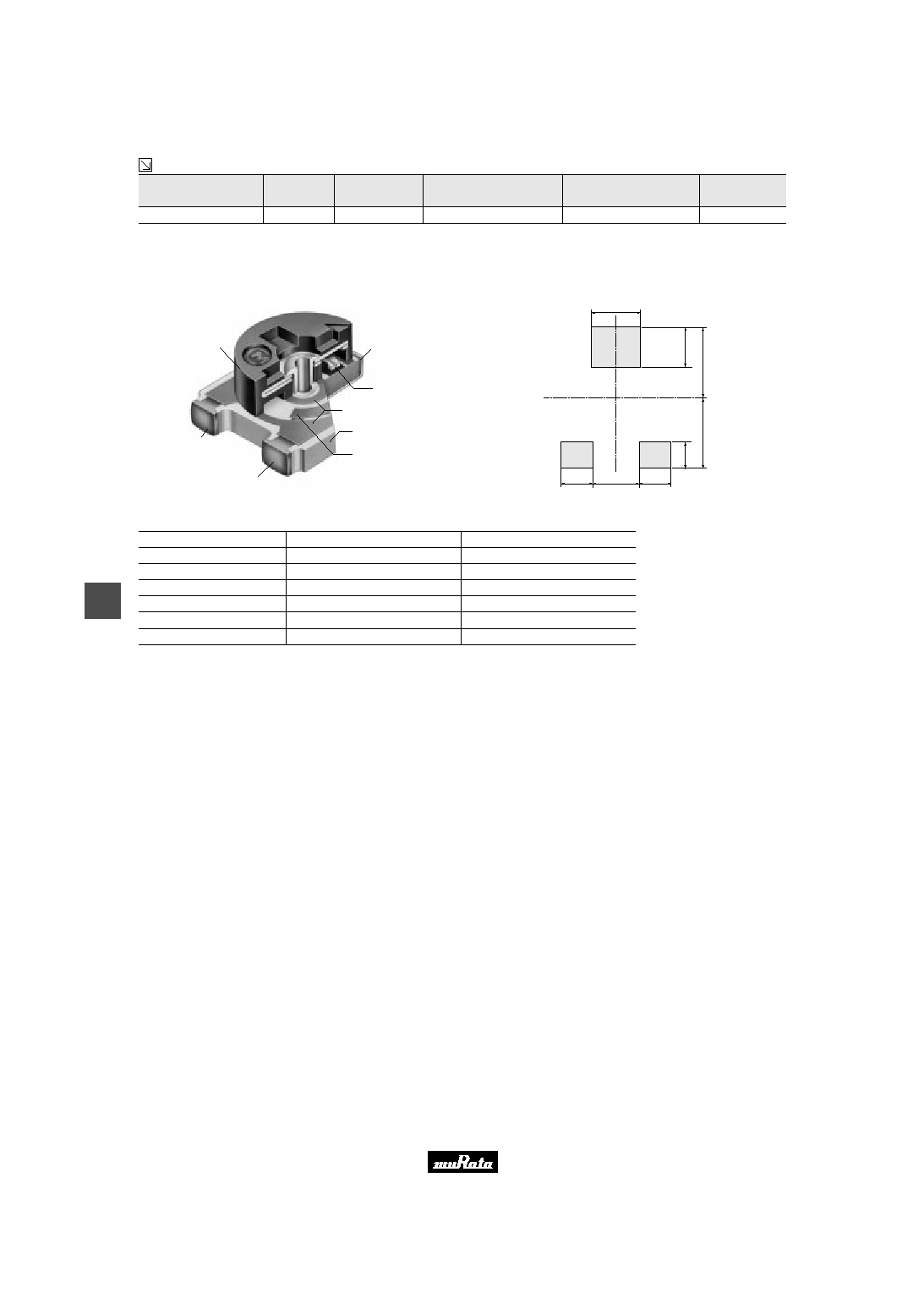
s Construction
Driver Plate
#1 Terminal
#3 Terminal
#2 Terminal
Wiper
Resistive
Element
Ceramic
Substrate
Rubber
s Standard Land Dimension
1.7
1
.
8
3
.
2
1
.
2
3
.
2
1.1
1.6
1.1
in mm
(
Tolerance :
Ī
0.1
)
s Characteristics
Item
PVM4A
ppp
A01
PVM4A
ppp
B01
Res. Change :
Ī
3%
Humidity Exposure
Res. Change :
Ī
2%
Res. Change :
Ī
3%
High Temperature Exposure
Res. Change :
Ī
2%
Res. Change :
Ī
3%
Humidity Load Life
Res. Change :
Ī
3%
Res. Change :
Ī
3%
Temperature Load Life
Res. Change :
Ī
3%
Res. Change :
Ī
3%
Temperature Cycle
Res. Change :
Ī
2%
Res. Change :
Ī
10% (20 cycles)
Rotational Life
Res. Change :
Ī
5% (100 cycles)
Please read rating and
!
CAUTION (for storage and operating, rating, soldering and mounting, handling) in this PDF catalog to prevent smoking and/or burning, etc.
This catalog has only typical specifications. Therefore, you are requested to approve our product specification or to transact the approval sheet for product specificaion before ordering.
!
Note
R50E12.pdf 02.9.5

PVM4 Series Notice
31
5
!
Note
∑ Please read rating and
!
CAUTION (for storage and operating, rating, soldering and mounting, handling) in this catalog to prevent smoking and/or burning, etc.
∑ This catalog has only typical specifications because there is no space for detailed specifications. Therefore, please approve our product specification or transact the approval sheet for product specification before ordering.
s Notice (Operating and Storage Conditions)
1. Store that the temperature is -10 to +40deg. C and
the relative humidity is 30-85%RH.
2. Do not store in or near corrosive gases.
3. Use within six months after delivery.
4. Open the package just before using.
5. Do not store under direct sunlight.
6. The trimmer potentiometer should not be used under
the following environmental conditions:
If you use the trimmer potentiometer in an
environment other these listed below, please
consult with Murata factory representative prior to
using.
(1) Corrosive gaseous atmosphere.
(Ex. Chlorine gas, Hydrogen sulfide gas, Ammonia
gas, Sulfuric acid gas, Nitric oxie gas, etc.)
(2) In liquid.
(Ex. Oil, Medical liquid, Organic solvent, etc.)
(3) Dusty/dirty atmosphere.
(4) Direct sunlight.
(5) Static voltage nor electric/magnetic fields.
(6) Direct sea breeze.
(7) Other variations of the above.
s Notice (Rating)
1. When using with partial load (rheostat), minimize
the power depend on the resistance value.
2. The maximum input voltage to a trimmer
potentiometer should not exceed (P∑R)^1/2 or the
maximum operating voltage, whichever is smaller.
3. The maximum input current to a trimmer
potentiometer should not exceed (P/R)^1/2 or the
allowable wiper current, whichever is smaller.
s Notice (Soldering and Mounting)
1. Soldering
(1) Can be soldered by reflow soldering method, flow
soldering method, and soldering iron. (Incase
of flow soldering, it is necessary to clean
after soldering.)
(2) Use our standard land dimension. Excessive land
area causes displacement due to effect of the
surface tension of the solder. Insufficient
land area leads to insufficient soldering
strength of the chip.
(3) Standard soldering condition
(a) Reflow and flow soldering :
Refer to the standard temperature profile.
(b) Soldering iron:
>Temperature of tip 260deg.C max.
>Soldering time 3sec. max.
>Diameter 2mm dia. max.
>Wattage of iron 30W max.
Before using other soldering conditions than
those listed above, please consult with Murata
factory representative prior to using. If the
soldering conditions are not suitable, e. g.,
excessive time and/or excessive temperature,
the trimmer potentiometer may deviate from the
specified characteristics.
(4) Apply the appropriate amount of solder paste.
The thickness of solder paste should be printed
from 100micro m to 150micro m and the dimension
of land pattern should be used Murata's
standard land pattern at reflow soldering.
Insufficient amounts of solder can lead to
insufficient soldering strength on PCB.
Excessive amounts of solder may cause the
bridging between the terminals.
(5) The soldering iron should not come in contact
with the case of the trimmer potentiometer. If
such contact does occur, the trimmer
potentiometer may be damaged.
2. Mounting
(1) Do not apply excessive force (preferable 9.8N
(Ref.; 1kgf) max.), when the trimmer
potentiometer is mounted to the PCB.
(2) Do not warp and/or bend PC board to prevent
trimmer potentiometer from breakage.
(3) In chip placers, the recommended size of the
cylindrical pick-up nozzle should be outer
dimension 4.0mm dia. and inner dimension 2.0mm
dia..
3. Cleaning
(1) Isopropyl alcohol and Ethyl alcohol are
available material for cleaning.
For other materials, please consult with Murata
factory representative prior to using.
(2) The total cleaning time by cold dipping method
shall be less than 5 minutes.
The total cleaning time by hot dipping method
shall be less than 2 minutes.
The total cleaning time by ultrasonic washing
(conditions as below) method shall be less than
1 minutes.
Continued on the following page.
Please read rating and
!
CAUTION (for storage and operating, rating, soldering and mounting, handling) in this PDF catalog to prevent smoking and/or burning, etc.
This catalog has only typical specifications. Therefore, you are requested to approve our product specification or to transact the approval sheet for product specificaion before ordering.
!
Note
R50E12.pdf 02.9.5
PVM4 Series Notice
32
5
!
Note
∑ Please read rating and
!
CAUTION (for storage and operating, rating, soldering and mounting, handling) in this catalog to prevent smoking and/or burning, etc.
∑ This catalog has only typical specifications because there is no space for detailed specifications. Therefore, please approve our product specification or transact the approval sheet for product specification before ordering.
Continued from the preceding page.
In case of the mixed conditions with hot dipping
and ultrasonic washing, the cleaning time by hot
dipping shall be less than 1 minutes and the
cleaning time by ultrasonic washing shall be
less than 1 minutes. In case of the mixed
conditions with hot dipping, ultrasonic washing
and vaper, the cleaning time by hot dipping
shall be less than 1 minutes, the cleaning time
by ultrasonic washing shall be less than 30
seconds and the cleaning time by vaper shall be
less than 30 seconds.
If the trimmer potentiometer is cleaned by
other conditions,the sealing construction may
be damaged. Due to the ultra-sonic cleaning
equipment peculiar self resonance point and the
cleaning compatibility usually depends on the
jig construction and/or the cleaning condition
such as the depth of immersion, please check
the cleaning equipment to determine the
suitable conditions.
If the trimmer potentiometer is cleaned by
other conditions, the trimmer potentiometer may
be damaged.
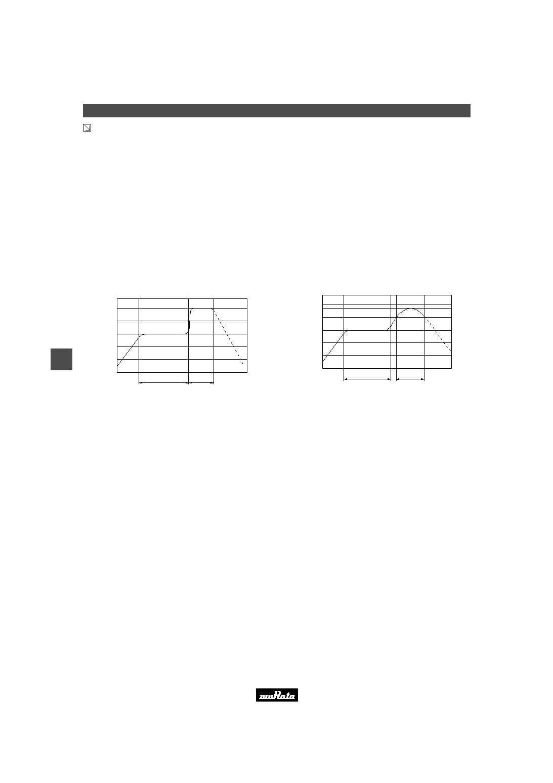
s Flow Soldering Standard Profile
250
200
100
0
60~120 sec.
5 sec. max.
Time
T
e
m
p
e
r
a
t
u
r
e
(
į
C
)
For flow soldering
Pre-heating(in the air)
Soldering
Gradual Cooling
(in the air)
s Reflow Soldering Standard Profile
230
200
100
0
60~120 sec.
30 sec. max.
(Melting zone)
Time
T
e
m
p
e
r
a
t
u
r
e
(
į
C
)
For reflow soldering
Pre-heating(in the air)
Soldering
Gradual Cooling
(in the air)
s Notice (Handling)
1. Use suitable screwdrivers that fit comfortably in
driver slot. We recommend the below screwdriver.
* Recommended screwdriver for manual adjustment
VESSEL MFG.: NO. 9000-2.6x30
(Murata P/N : KMDR120)
We can supply above screwdrivers.
If you place order, please nominate Murata P/N.
2. Don't apply more than 4.9N (Ref.; 500gf) of twist
and stress after mounted onto PCB to prevent
contact intermittence. If excessive force is
applied, the trimmer potentiometer may not
function.
3. Please use within the effective rotational angle.
The potentiometer dose not have a mechanical stop
for over rotation. In case out of effective
rotational angle, the trimmer potentiometer may
not function.
4. When using a lock paint to fix slot position,
please use adhesive resin without chlorine or
sulfur (Three-bond "1401series").
s Notice (Other)
1. Please make sure that your product has been
evaluated and confirmed against your
specifications when our product is mounted to your
product.
2. Murata connot guarantee trimmer potentiometer
integrity when used under conditions other than
those specified in this document.
Please read rating and
!
CAUTION (for storage and operating, rating, soldering and mounting, handling) in this PDF catalog to prevent smoking and/or burning, etc.
This catalog has only typical specifications. Therefore, you are requested to approve our product specification or to transact the approval sheet for product specificaion before ordering.
!
Note
R50E12.pdf 02.9.5

No.
Item
Test Methods
Total Resistance
1
Measure total resistance between the resistance element and terminals (terminals #1 and #3) with the contact arm
positioned against a stop. The positioning of the contact arm and terminal shall be the same for subsequent total
resistance measurements on the same device.
Use the test voltage specified in Table-1 for total resistance measurements. This voltage shall be used whenever a
subsequent total resistance measurement is made.
Specifications and Test Methods
Residual Resistanc
2
Position the contact arm at the extreme counterclockwise limit of mechanical travel and measure the resistance
between the contact arm and the corresponding end terminal. Then, position the contact arm at the extreme clock-
wise limit of mechanical travel and measure the resistance between the contact arm and the corresponding end ter-
minal. During this test, take suitable precautions to ensure that the rated current of the resistance element is not
exceeded.
Contact Resistance
3
4
1
Total resistance,
Nominal (ohm)
10
V
R
V
100
100
F
R
V
1k
1k
F
R
V
10k
10k
F
R
V
100k
100k
F
R
1.0
Maximum Test
Voltage (V)
Rx
1
2
3
Proofreaded
Resistence
AC
Amplifier
Oscilloscope
Rx : Trimmer Potentiometer
Oscilloscope bandwidth :100Hz to 50kHz
Constant Current
Source not to
Exceed Rating of
Unit Being Tested
Figure-1 CRV measuring circuit
Table-1 Total resistance test voltage
3.0
10.0
30.0
100.0
Contact resistance variation shall be measured with the measuring circuit shown in below, or its equivalent. The
operating wiper shall be rotated in both directions through 90% of the actual effective-electrical travel for a total of 6
cycles.
The rate of rotation of the operating wiper shall be such that the wiper completes 1 countin determining whether or
not a contact resistance variation is observed at least twice in the same location. The test current shall follow the
value given in Table-2 unless otherwise limited by the power rating.
Standard total
resistance R (ohm)
100
V
R
F
10k
10k
V
R
F
100k
100
V
R
10mA Max.
Test Current
Table-2 Test current for CRV
1mA Max.
100ĶA Max.
Humidity Exposure
The wiper contact point shall be pre-setted at about 50% position of effective rotational angle. After that, the poten-
tiometer shall be placed in a chamber at 40Ī2įC and 90 - 95% without loading for 500Ī12 hours.
The resistance value shall be measured after keeping the potentiometer in a room for 5Ī1/6 hours.
5
High Temperature
Exposure
The wiper contact point shall be pre-setted at about 50% position of effective rotational angle. After that, the poten-
tiometer shall be placed in a chamber at 70Ī2įC without loading for 500Ī12 hours. The resistance value shall be
measured after keeping the potentiometer in a room for 1.5Ī1/6 hours.
6
Humidity Load Life
The wiper contact point shall be pre-setted at about 50% position of effective rotational angle. After that, the poten-
tiometer shall be placed in a chamber at 40Ī2įC and 90 - 95% with loading the 1/2 rated voltage between #1 and #2
terminals, intermittently 1.5 hours ON and 0.5 hours OFF for 1000Ī12hours.
The resistance value shall be measured after keeping the potentiometer in a room for 5Ī1/6 hours.
7
Load Life
The wiper contact point shall be pre-setted at about 50% position of effective rotational angle. After that, the poten-
tiometer shall be placed in a chamber at 70Ī2įC (50Ī2įC for PVZ) with loading the 1/2 rated voltage between #1
and #2 terminals, intermittently 1.5 hours ON and 0.5 hours OFF for 1000Ī12 hours. The resistance value shall be
measured after keeping the potentiometer in a room for 1.5Ī1/6 hours.
The tests and measurements shall be conducted under the condition of 15 to 35įC of temperature, 25 to 75% of relative humidity and 86 to 106 kpa of
atmospheric pressure unless otherwise specified. In case when entertained a doubt in judgment obtained from results measured in accordance with the
above mentioned conditions, the tests and measurements shall be conducted under the condition of 25Ī2įC of temperature and, 45 to 55% of relative
humidity and 86 to 106 kpa of atmospheric pressure.
8
Temperature Cycle
The wiper contact point shall be pre-setted at about 50% position of effective rotational angle. After that, the poten-
tiometer shall be subjected to Table-3,Table-4 temperature for 5 cycles. The resistance value shall be measured
after keeping the potentiometer in a room for 1.5Ī10 minutes.
Sequence
Temp. (įC)
-25Ī3
1
Table-3 PVZ
Time (min.)
+25Ī2
2
3
+85Ī3
+25Ī2
4
30Ī3
10Max.
Sequence
Temp. (įC)
-55Ī3
1
Table-4 PVA3/PVS3/PVM4A
---
A01
Time (min.)
30Ī3
+25Ī2
2
10Max.
3
+125Ī3 +25Ī2
4
30Ī3
10Max.
Continued on the following page.
10Max.
30Ī3
SMD Open Type and PVM4A_A01 Series Specifications and Test Methods
70
9
!
Note
∑ Please read rating and
!
CAUTION (for storage and operating, rating, soldering and mounting, handling) in this catalog to prevent smoking and/or burning, etc.
∑ This catalog has only typical specifications because there is no space for detailed specifications. Therefore, please approve our product specification or transact the approval sheet for product specification before ordering.
Please read rating and
!
CAUTION (for storage and operating, rating, soldering and mounting, handling) in this PDF catalog to prevent smoking and/or burning, etc.
This catalog has only typical specifications. Therefore, you are requested to approve our product specification or to transact the approval sheet for product specificaion before ordering.
!
Note
R50E12.pdf 02.9.5

Specifications and Test Methods
The trimmer potentiometer shall be subjected to the following each temperature (see Table-5,Table-6) for 30 to 45
minutes. The resistance value shall be measured in the chamber.
TCR=
Z
10
6
(ppm/įC)
T
1
: Reference temperature in degrees celsius
T
2
: Test temperature in degrees celsius
R
1
: Resistance at reference temperature in ohm
R
2
: Resistance at test temperature in ohm
R
2
≠ R
1
R
1
(T
2
≠ T
1
)
The wiper shall be rotated over 90% of the effective rotational angle without loading at a speed of 10 cycles per
minute, for 10 cycles continuously. The resistance value shall be measured after keeping the potentiometer in a
room for 10Ī5 minutes.
Sequence
Temp. (įC)
+25Ī2
1*
Table-5 PVZ
-25Ī3
2
3*
+25Ī2
+85Ī3
4
No.
Item
Test Methods
Temperature Coefficient of
Resistance
Rotational Life
9
10
Sequence
Temp. (įC)
+25Ī2
1
Table-6 PVA3/PVS3/PVM4A
---
A01
-55Ī3
2
3*
+25Ī2 +125Ī3
4
Continued from the preceding page.
Note)*:Norm Temp.
SMD Open Type and PVM4A_A01 Series Specifications and Test Methods
71
9
!
Note
∑ Please read rating and
!
CAUTION (for storage and operating, rating, soldering and mounting, handling) in this catalog to prevent smoking and/or burning, etc.
∑ This catalog has only typical specifications because there is no space for detailed specifications. Therefore, please approve our product specification or transact the approval sheet for product specification before ordering.
Please read rating and
!
CAUTION (for storage and operating, rating, soldering and mounting, handling) in this PDF catalog to prevent smoking and/or burning, etc.
This catalog has only typical specifications. Therefore, you are requested to approve our product specification or to transact the approval sheet for product specificaion before ordering.
!
Note
R50E12.pdf 02.9.5