90
Short circuit protection
(Non latch type).
Controls only DC load.
VDE
mm
inch
6.4
.252
3.9
.154
8.8
.346
6.4
.252
3.6
.142
8.8
.346
1
2
3
6
5
4
FEATURES
1. Protects Circuit from excess current
The short circuit protection function
prevents the continued flow of short
current. After short current is detected,
load current is monitored, and if the load
returns to normal, the relay returns to
normal operation.
2. No need for fuses, polyswitches, or
other protectors
The built-in short circuit protection
function eliminates the need for
overcurrent protectors, reducing
mounting costs and space requirements.
3. High capacity
Can control up to 0.5A (60 VDC) load
current.
TYPICAL APPLICATIONS
∑ Industrial equipment
∑ Traffic signal control
∑ Security equipment
TYPES
*Indicate the DC values.
Note: For space reasons, the SMD terminal shape indicator "A" and the package type indicator "X" and "Z" are omitted from the seal.
Type
I/O isolation
voltage
Output rating*
Part No.
Packing quantity
Through hole
terminal
Surface-mount terminal
Load
voltage
Load
current
Tube packing style
Tape and reel packing style
Tube
Tape and reel
Picked from the
1/2/3-pin side
Picked from the
4/5/6-pin side
DC
type
1,500 V
60 V
500 mA
AQV112KL
AQV112KLA
AQV112KLAX
AQV112KLAZ
1 tube contains
50 pcs.
1 batch contains
500 pcs.
1,000 pcs.
RATING
1. Absolute maximum ratings (Ambient temperature: 25
∞
C
77
∞
F
)
Item
Symbol
AQV112KL(A)
Remarks
Input
LED forward current
I
F
50 mA
LED reverse voltage
V
R
5 V
Peak forward current
I
FP
1 A
f = 100 Hz, Duty factor = 0.1%
Power dissipation
P
in
75 mW
Output
Load voltage (peak DC)
V
L
7 to 60V
Continuous load current (peak DC)
I
L
0.5 A
Power dissipation
P
out
500 mW
Total power dissipation
P
T
550 mW
I/O isolatiom voltage
V
iso
1,500 V AC
Temperature limits
Operating
T
opr
≠40
∞
C to +85
∞
C
≠40
∞
F to +185
∞
F
Non-condensing at low temperatures
Storage
T
stg
≠40
∞
C to +100
∞
C
≠40
∞
F to +212
∞
F
GU PhotoMOS
(AQV112KL)

GU PhotoMOS (AQV112KL)
91
2. Electrical characteristics (Ambient temperature: 25
∞
C
77
∞
F
)
For type of connection, see Page 33.
Note: Recommendable LED forward current IF = 10 mA.
*Turn on/Turn off time
I
For Dimensions, see Page 29.
I
For Schematic and Wiring Diagrams, see Page 33.
I
For Cautions for Use, see Page 38.
Item
Symbol
AQV112KL(A)
Condition
Input
LED operate current
Typical
I
Fon
0.8 mA
I
L
= 100mA
Maximum
10 mA
LED turn off current
Minimum
I
Foff
0.3 mA
I
L
= 100mA
Typical
0.7 mA
LED dropout voltage
Typical
V
F
1.35 V (1.17 V at I
F
= 10 mA)
I
F
= 50 mA
Maximum
1.5 V
Output
On resistance
Typical
R
on
0.55
I
F
= 10 mA
I
L
= Max.
Maximum
2.0
Load short circuit detection voltage
Typical
V
LSHT
5 V
I
F
= 10 mA
Maximum
7 V
Off state leakage current
Maximum
I
Leak
1
µ
A
I
F
= 0 mA
V
L
= Max.
Transfer
characteristics
Turn on time*
Typical
T
on
2.0 ms
I
F
= 10 mA
I
L
= 100 mA
V
L
= 10 V
Maximum
5.0 ms
Turn off time*
Typical
T
off
0.1 ms
I
F
= 10 mA
I
L
= 100 mA
V
L
= 10 V
Maximum
1.0 ms
I/O capacitance
Typical
C
iso
0.8 pF
f = 1 MHz
V
B
= 0 V
Maximum
1.5 pF
Initial I/O isolation resistance
Minimum
R
iso
1,000 M
500 V DC
Toff
Input
Output
Ton
90%
10%
REFERENCE DATA
1. Load current vs. ambient temperature
characteristics
Allowable ambient temperature: ≠40
∞
C to +85
∞
C
≠40
∞
F to +185
∞
F
2. On resistance vs. ambient temperature
characteristics
Measured portion: between terminals 4 and 6;
LED current: 10 mA; Load current: Max.(DC)
3. Turn on time vs. ambient temperature
characteristics
Measured portion: between terminals 4 and 6;
LED current: 10 mA; Load voltage: 10V (DC);
Load current: 100 mA
0
100
200
300
400
500
600
0
20
40
60
8085 100
≠40
≠20
Ambient temperature,
∞C
Load current, mA
0
0.5
1
1.5
2
≠40
≠20
0
20
40
60
8085
Ambient temperature,
∞C
On resistance,
0
2
3
≠40
≠20
5
0
20
40
60
80
1
4
85
Ambient temperature,
∞C
Turn on time, ms

GU PhotoMOS (AQV112KL)
92
4. Turn off time vs. ambient temperature
characteristics
Measured portion: between terminals 4 and 6;
LED current: 10 mA; Load voltage: 10 V (DC);
Load current: 100 mA (DC)
5. LED operate current vs. ambient
temperature characteristics
Measured portion: between terminals 4 and 6;
Load current: 100 mA
6. LED turn off current vs. ambient temperature
characteristics
Measured portion: between terminals 4 and 6;
Load current: 100 mA
0
0.05
0.1
0.15
0.2
0.25
≠40
≠20
0.3
0
20
40
60
8085
Ambient temperature,
∞C
Turn off time, ms
0
0.5
1
1.5
2
2.5
≠40
≠20
3
0
20
40
60
8085
Ambient temperature,
∞C
LED operate current, mA
0
0.5
1
1.5
2
2.5
≠40
≠20
3
0
20
40
60
8085
Ambient temperature,
∞C
LED turn off current, mA
7. Off state leakage current vs. load voltage
characteristics
Measured portion: between terminals 4 and 6;
Ambient temperature: 25
∞
C
77
∞
F
8. Current vs. voltage characteristics of output
at MOS portion
Measured portion: between terminals 4 and 6;
Ambient temperature: 25
∞
C
77
∞
F
9. LED dropout voltage vs. ambient
temperature characteristics
Measured portion: between terminals 1 and 2;
LED current: 10 to 50 mA
20
30
40
50
60
10
0
10
-12
10
-11
10
-10
10
-9
10
-8
10
-7
10
-6
Load voltage, V
Off state leakage current, A
≠0.6
≠0.4
≠0.2
0
0.2
0.4
0.6
≠1
≠0.5
0
0.5
1
Voltage, V
Current, A
1
1.2
1.3
≠40
≠20
1.5
0
20
40
60
80
1.1
1.4
85
Ambient temperature,
∞C
LED dropout voltage, V
50mA
30mA
20mA
10mA
10. Turn on time vs. LED forward current
characteristics
Measured portion: between terminals 4 and 6;
Load voltage: 10 V (DC); Load current: 100 mA (DC);
Ambient temperature: 25
∞
C
77
∞
F
11. Turn off time vs. LED forward current
characteristics
Measured portion: between terminals 4 and 6;
Load voltage: 10 V (DC); Load current: 100 mA (DC);
Ambient temperature: 25
∞
C
77
∞
F
12. Output capacitance vs. applied voltage
characteristics
Measured portion: between terminals 4 and 6;
Frequency: 1 MHz; Ambient temperature: 25
∞
C
77
∞
F
≠1
4
3
2
1
0
5
0
10
20
30
40
50
LED forward current, mA
Turn on time, ms
0
0.05
0.1
0.15
0.2
0
10
20
30
40
50
LED forward current, mA
Turn off time, ms
0
100
200
300
400
500
0
10
20
30
40
50
60
Applied voltage, V
Output capacitance, pF
13. Short circuit peak current vs. time
characteristics
Measured portion: between terminals 4 and 6;
LED current: 10 mA; Load resistance: 0;
Ambient temperature: 25
∞
C
77
∞
F
14. Short current monitoring interval vs. time
characteristics
Measured portion: between terminals 4 and 6;
LED current: 10 mA; Load resistance: 0;
Ambient temperature: 25
∞
C
77
∞
F
1
1.5
2
V
L
=12V
V
L
=24V
V
L
=60V
2.5
3
4
3.5
0
10
20
30
40
50
60
Time, S
Short circuit peak current, A
V
L
=12V
V
L
=24V
V
L
=60V
0
5
10
15
20
30
25
0
10
20
30
40
50
60
Time, S
Short current monitoring interval, ms
GU PhotoMOS (AQV112KL)
93
What is short circuit protection Non-latch type?
If the load current reaches a
predetermined overcurrent level, the
output-side short circuit protection
function cuts off the load current. It then
monitors the load current, and if it returns
to normal, automatically recovers to
normal relay operation.
In order to operate the short circuit
protection function, ensure that the input
current is at least I
F
= 10 mA.
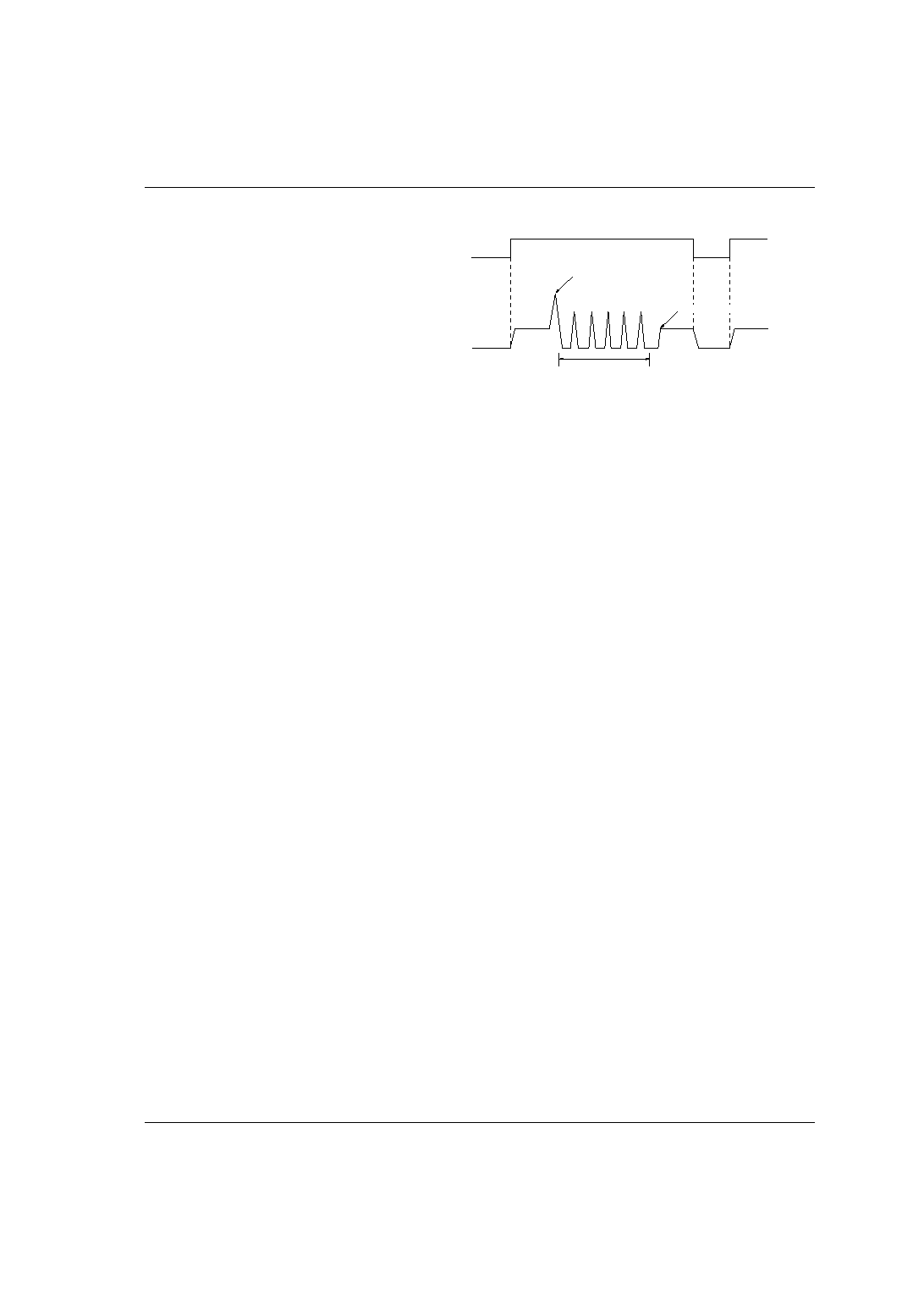
Operation chart (Non-latch type)
Input Current
Output Current
1 Load short detected
2 Function operation
3 Load turn off