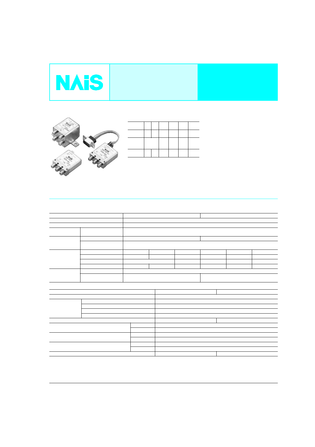
RD
1
RD COAXIAL
SWITCHES
26.5GHz, 18GHz
COAXIAL SWITCH
Transfer type is coming soon.
FEATURES
1. High frequency characteristics
(Impedance 50
)
*: 18 to 26.5GHz characteristics can be applied
26.5GHz type only
2. SPDT and transfer type available
3. High sensitivity
Nominal operating power:
840 mW (SPDT, Failsafe type)
1540 mW (Transfer, Failsafe type)
4. Long life: 5
◊
10
6
(SPDT)
Frequency
(GHz)
≠1
≠4
≠8
≠12.4
≠18
≠26.5*
V.S.W.R.
(max.)
1.1 1.15 1.25
1.35
1.5
1.7
Insertion
loss
(dB. max.)
0.2
0.3
0.4
0.5
0.8
Isolation
(dB. min.)
85
80
70
65
60
55
TYPICAL APPLICATIONS
Wireless and mobile communication
infrastructure
∑ Cellular phone base stations
∑ Amplifier switching
Measurement instruments
∑ All types of inspection equipment
ATTENTION
Transfer type is coming soon.
SPECIFICATIONS
Contact
Characteristics
Arrangement
SPDT
Transfer
Contact material
Gold plating
Initial contact resistance
Max. 100m
Rating
Contact input power*
1
120W 3GHz
(V.S.W.R 1.15 or less, no contact switching, ambient temperature 40∞C [SPDT], 25∞C [Transfer])
Indicator rating
Contact rating
Max. 30V 100mA
Max. 5V 100mA
Initial contact resistance
(Measured by 5V 100mA)
Max. 1
High frequency
characteristics
(Impedance 50
)
to 1 GHz
1 to 4
4 to 8
8 to12.4
12.4 to 18
18 to 26.5
V.S.W.R. (max.)
1.1
1.15
1.25
1.35
1.5
1.7
Insertion loss (dB, max.)
0.2
0.3
0.4
0.5
0.8
Isolation (dB, min.)
85
80
70
65
60
55
Expected life
(min. operation)
Mechanical (at 180 cpm)
5
◊
10
6
Electrical (at 20 cpm)
5
◊
10
6
(5W, to 3GHz, impedance 50
,
V.S.W.R.; max. 1.2)
10
6
(5W, to 3GHz, impedance 50
,
V.S.W.R.; max. 1.2)
SPDT
Transfer
Initial insulation resistance*
2
Min. 1,000 M
Initial breakdown
voltage*
3
Between open contacts
500 Vrms for 1 min.
Between contact and coil
500 Vrms for 1 min.
Between contact and earth terminal
500 Vrms for 1 min.
Between coil and earth terminal
500 Vrms for 1 min.
Operate time*
4
(at 20∞C)
Max. 15ms
Max. 20ms
Shock resistance
Functional*
5
500 m/s
2
Destructive*
6
1,000 m/s
2
Vibration resistance
Functional*
7
10 to 55 Hz at double amplitude of 3mm
Destructive
10 to 55 Hz at double amplitude of 5mm
Conditions for operation, transport and storage*
8
(Not freezing and condensing at low temperature)
Ambient temp
≠55∞C to +85∞C
≠67∞F to +185∞F
Humidity
5 to 85% R.H.
Unit weight (Approx.)
50g
1.76oz
110g
3.88oz
Remarks
*
1
Please verify the usability of input power under actual conditions because heat
generated from connectors can influence connection.
*
2
Measurement at same location as "Initial breakdown voltage" section.
*
3
Detection current: 10mA
*
4
Nominal operating voltage applied to the coil, excluding contact bounce time.
*
5
Half-wave pulse of sine wave: 11ms, detection time: 10
µ
s.
*
6
Half-wave pulse of sine wave: 11ms
*
7
Detection time: 10
µ
s
*
8
Refer to 4. Conditions for operation, transport and storage mentioned in NOTES.
RD
2
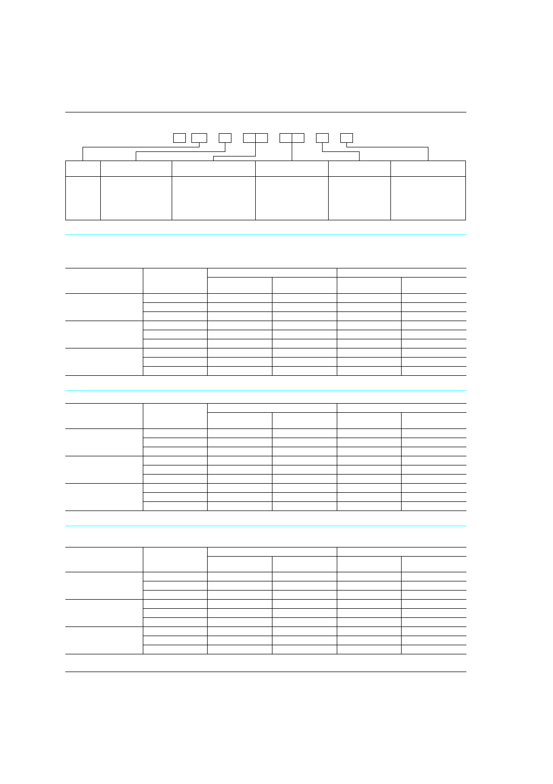
ORDERING INFORMATION
Note: Sealed types are also available. (SPDT type only)
Product
name
RD
Frequency
1: to 18GHz (SPDT)
2: to 18GHz (Transfer)
5: to 26.5GHz (SPDT)
6: to 26.5GHz (Transfer)
Operating function
00: Failsafe
20: Latching
51: Latching with TTL driver
(with self cut-off function)
Nominal operating
voltage, V DC
4H:
05:
12:
24:
4.5V (Failsafe,
Latching type only)
5V (Latching with
TTL driver type only)
12V
24V
Operation terminal
Nil:
C:
Solder terminal
Connector cable
(SPDT type only)
HF data attached
Nil:
Q:
No HF test data
attached
HF test data attached
RD
A
Ex.
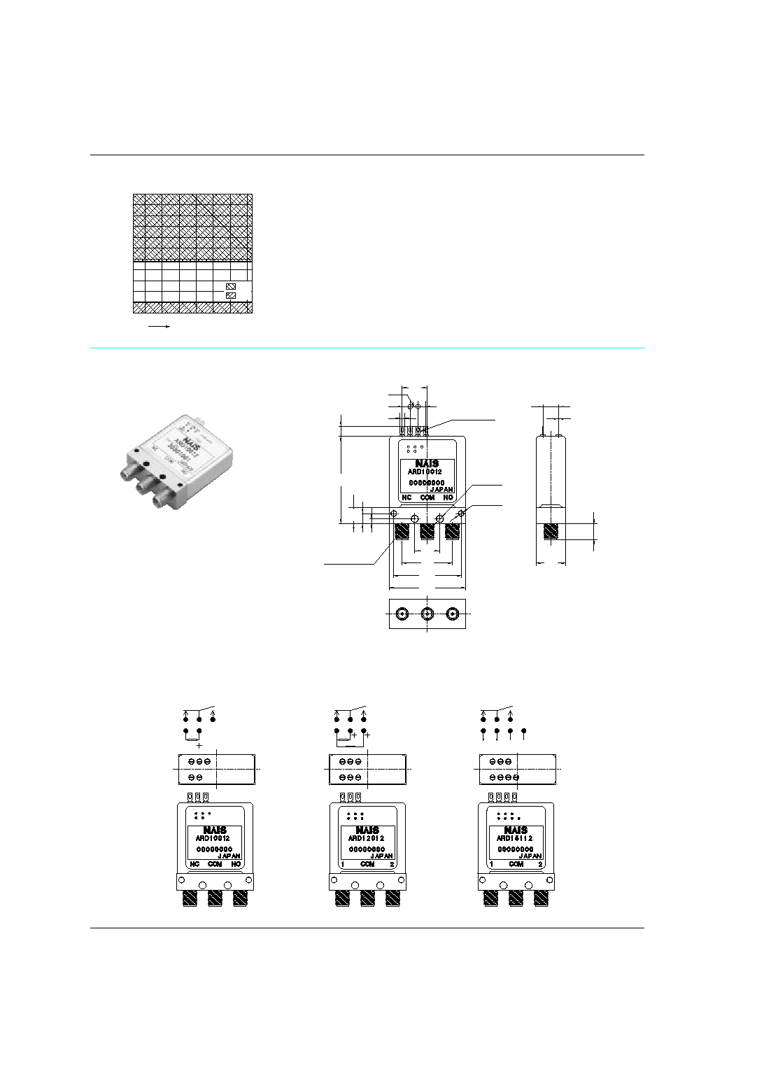
TYPES
1. SPDT
1) Solder terminal
Note: Standard packing; Carton: 1 pc. Case: 20 pcs.
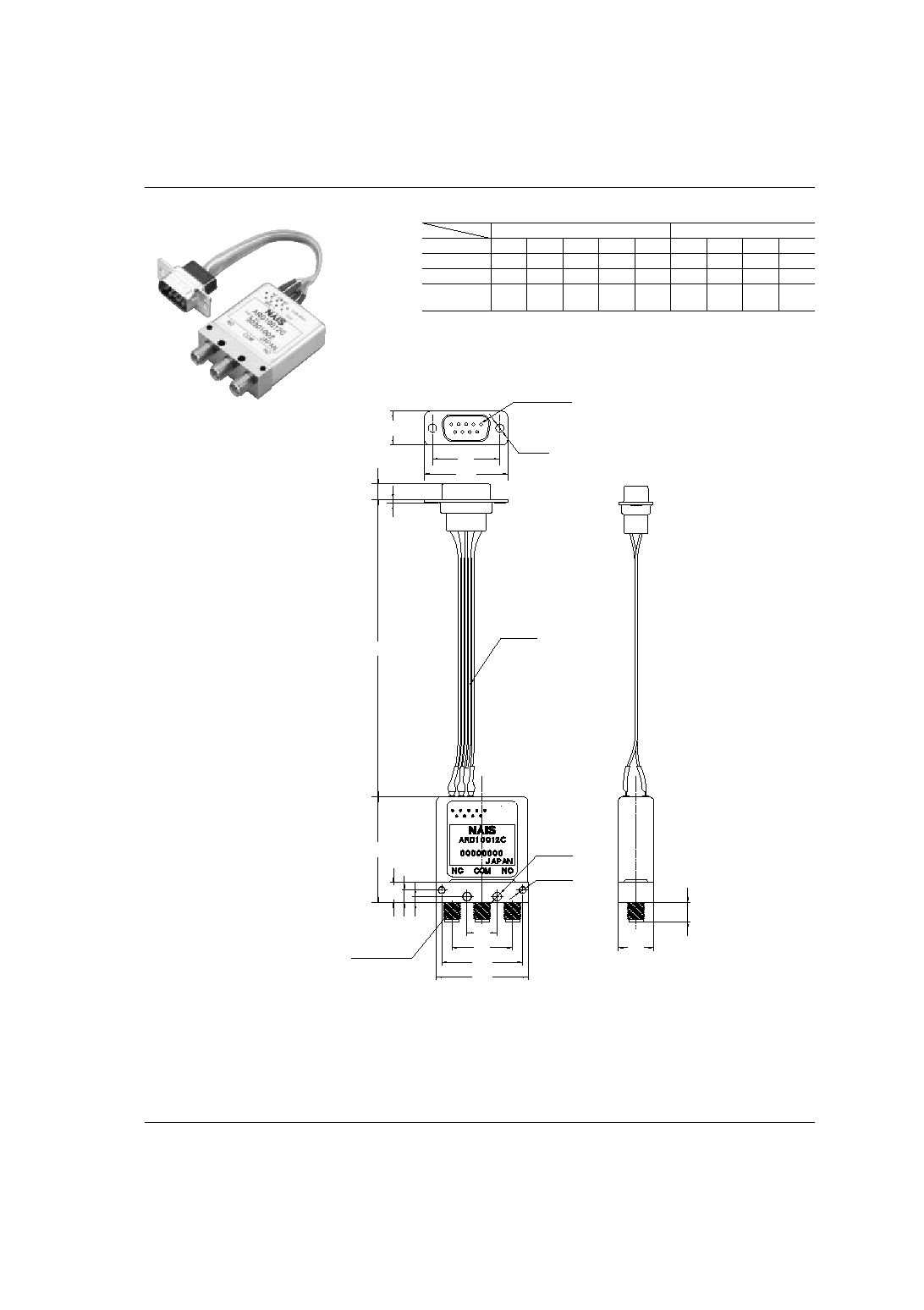
2) Connector cable
Note: Standard packing; Carton: 1 pc. Case: 10 pcs.
2. Transfer
1) Solder terminal
Note: Standard packing; Carton: 1 pc. Case: 10 pcs.
Operating function
Nominal operating
voltage, V DC
18GHz type
26.5GHz type
No HF datasheet
attached
HF datasheet
attached
No HF datasheet
attached
HF datasheet
attached
Failsafe
4.5
ARD1004H
ARD1004HQ
ARD5004H
ARD5004HQ
12
ARD10012
ARD10012Q
ARD50012
ARD50012Q
24
ARD10024
ARD10024Q
ARD50024
ARD50024Q
Latching
4.5
ARD1204H
ARD1204HQ
ARD5204H
ARD5204HQ
12
ARD12012
ARD12012Q
ARD52012
ARD52012Q
24
ARD12024
ARD12024Q
ARD52024
ARD52024Q
Latching with TTL driver
(with self cut-off function)
5
ARD15105
ARD15105Q
ARD55105
ARD55105Q
12
ARD15112
ARD15112Q
ARD55112
ARD55112Q
24
ARD15124
ARD15124Q
ARD55124
ARD55124Q
Operating function
Nominal operating
voltage, V DC
18GHz type
26.5GHz type
No HF datasheet
attached
HF datasheet
attached
No HF datasheet
attached
HF datasheet
attached
Failsafe
4.5
ARD1004HC
ARD1004HCQ
ARD5004HC
ARD5004HCQ
12
ARD10012C
ARD10012CQ
ARD50012C
ARD50012CQ
24
ARD10024C
ARD10024CQ
ARD50024C
ARD50024CQ
Latching
4.5
ARD1204HC
ARD1204HCQ
ARD5204HC
ARD5204HCQ
12
ARD12012C
ARD12012CQ
ARD52012C
ARD52012CQ
24
ARD12024C
ARD12024CQ
ARD52024C
ARD52024CQ
Latching with TTL driver
(with self cut-off function)
5
ARD15105C
ARD15105CQ
ARD55105C
ARD55105CQ
12
ARD15112C
ARD15112CQ
ARD55112C
ARD55112CQ
24
ARD15124C
ARD15124CQ
ARD55124C
ARD55124CQ
Operating function
Nominal operating
voltage, V DC
18GHz type
26.5GHz type
No HF datasheet
attached
HF datasheet
attached
No HF datasheet
attached
HF datasheet
attached
Failsafe
4.5
ARD2004H
ARD2004HQ
ARD6004H
ARD6004HQ
12
ARD20012
ARD20012Q
ARD60012
ARD60012Q
24
ARD20024
ARD20024Q
ARD60024
ARD60024Q
Latching
4.5
ARD2204H
ARD2204HQ
ARD6204H
ARD6204HQ
12
ARD22012
ARD22012Q
ARD62012
ARD62012Q
24
ARD22024
ARD22024Q
ARD62024
ARD62024Q
Latching with TTL driver
(with self cut-off function)
5
ARD25105
ARD25105Q
ARD65105
ARD65105Q
12
ARD25112
ARD25112Q
ARD65112
ARD65112Q
24
ARD25124
ARD25124Q
ARD65124
ARD65124Q

RD
3
COIL DATA (at 20∞C
68∞F
)
1. SPDT
1) Failsafe type
2) Latching type
3) Latching with TTL driver type (with self cut-off function)
2. Transfer
1) Failsafe type
2) Latching type
3) Latching with TTL driver type (with self cut-off function)
Nominal operating voltage,
V DC
Coil resistance,
(±:10%)
Nominal power consumption, mW
4.5
24.2
840
12
172
840
24
594
970
Nominal operating voltage,
V DC
Coil resistance,
(±:10%)
Nominal power consumption, mW
4.5
28.9
700
12
192
750
24
640
900
Nominal operating voltage,
V DC
TTL logic level (see TTL logic level range)
Switching frequency
ON
OFF
5
2.4 to 5.5V
0 to 0.5V
Max. 180 cpm
(ON time : OFF time = 1 : 1)
12
24
Nominal operating voltage,
V DC
Coil resistance,
(±:10%)
Nominal power consumption, mW
4.5
13.2
1540
12
93.6
1540
24
345
1670
Nominal operating voltage,
V DC
Coil resistance,
(±:10%)
Nominal power consumption, mW
4.5
16.8
1200
12
115
1250
24
411
1400
Nominal operating voltage,
V DC
TTL logic level (see TTL logic level range)
Switching frequency
ON
OFF
5
2.4 to 5.5V
0 to 0.5V
Max. 180 cpm
(ON time : OFF time = 1 : 1)
12
24
∑ Operating voltage range
1) Failsafe type
2) Latching type
3) Latching with TTL driver type
(with self cut-off function)
0
4
32
24
28
8
16
12
20
0
2
16
12
14
4
8
6
10
≠55≠40
0
≠20
20
Ambient temperature
∞
C
12
V
0
0.75
6
4.5
5.25
1.5
3
2.25
3.75
4.5
V
24
V
85
40
60
Nominal voltage
Allowable range
for use
Recommended
operation voltage range
Recommended
release voltage range
0
4
32
24
28
8
16
12
20
0
2
16
12
14
4
8
6
10
≠55≠40
0
≠20
20
85
40
60
Ambient temperature
∞
C
12
V
0
0.75
6
4.5
5.25
1.5
3
2.25
3.75
4.5
V
24
V
Allowable range
for use
Recommended
set/reset voltage range
Nominal voltage
0
4
32
24
28
8
16
12
20
0
2
16
12
14
4
8
6
10
≠55≠40
0
≠20
20
85
40
60
Ambient temperature
∞
C
12
V
0
0.83
6.67
5
5.83
1.67
3.33
2.5
4.17
5
V
24
V
Nominal voltage
Allowable range
for use
Recommended set/reset
voltage range