11
RX-RELAYS
SMALL MICRO WAVE RELAY
mm
inch
1. Excellent high frequency
characteristics (~2.5GHz, Impedance
50W)
∑ Insertion loss: 0.2 dB or less
∑ Isolation: 60 dB or more
∑ Insertion loss
∑ V.S.W.R./ Return loss: 1.2dB or less/
20.8dB or more
2. High sensitivity
∑ Nominal operating power: 200 mW
3. Small size
∑ Size: 20.5(L)
◊
12.4(W)
◊
9.4(H) mm
.807(L)
◊
.488(W)
◊
.370(H) inch
*Also available for unit support (contact us
for more details).
20.5
.807
9.4
.370
12.4
.488
0.4
0.5
0
0.1
0.3
0.2
300kHz
1.5GHz
2.5GHz 3GHz
COM-NC
COM-NO
Insertion loss, dB
Frequency
SPECIFICATIONS
Contact
Coil
(at 20∞C,
68∞F
)
Characteristics
Remarks
*1 Measurement at same location as "Initial breakdown voltage" section.
*2 Detection current: 10mA
*3 Nominal operating voltage applied to the coil, excluding contact bounce time.
*4 By resistive method, nominal voltage applied to the coil: Contact carrying power:
20W, at 2.5GHz, Impedance 50
, V.S.W.R.
&
1.2
*5 Half-wave pulse of sine wave: 11ms, detection time: 10
µ
s.
*6 Half-wave pulse of sine wave: 6ms
*7 Detection time: 10
µ
s
*8 Refer to 6. Conditions for operation, transport and storage mentioned in NOTES
Arrangement
1 Form C
Contact material
Gold
Initial contact resistance
Max. 100 m
Rating
Contact rating
10W (2.5 GHz,
Impedance 50
,
V.S.W.R.
&
1.2)
10mA 24V DC
(resistive load)
Contact carrying power
Max. 20W (at 40∞C,
V.S.W.R.
&
1.2, Average)
Max. switching voltage
30 V DC
Max. switching current
0.5 A DC
High frequency
characteristics
(~2.5GHz,
Impedance
50
)
V.S.W.R. (Return loss)
Max. 1.2 (Min. 20.8dB)
Insertion loss
Max. 0.2 dB
Isolation
Min. 60 dB
Input power
Max. 20W (at 40∞C,
V.S.W.R.
&
1.2, Average)
Expected life
(min.
operations)
Mechanical (at 180 cpm)
5
◊
10
6
Electrical
10mA 24 V DC
(resistive load)
3
◊
10
5
10W 2.5 GHz,
Impedance 50
,
V.S.W.R.
&
1.2
10
5
Nominal operating power
Single side stable
200 mW
1 coil latching
200 mW
2 coil latching
400 mW
Initial insulation resistance*
1
Min. 100 M
(at 500 V DC)
Initial
breakdown
voltage*
2
Between open contacts
500 Vrms
Between contact and coil
1,000 Vrms
Between contact and earth
terminal
500 Vrms
Operate time [Set time]*
3
(at 20∞C)
Max. 10ms (Approx. 6ms)
[Max. 10ms (Approx. 5ms)]
Release time (without diode) [Reset
time]*
3
Max. 6ms (Approx. 3ms)
[Max. 10ms (Approx. 5ms)]
Temperature rise (at 20∞C)*
4
Max. 60∞C
Shock resistance
Functional*
5
Min. 200 m/s
2
{20 G}
Destructive*
6
Min. 1,000 m/s
2
{100 G}
Vibration resistance
Functional*
7
10 to 55 Hz
at double amplitude of 3 mm
Destructive
10 to 55 Hz
at double amplitude of 5 mm
Conditions for operation,
transport and storage*
8
(Not freezing and
condensing at low
temperature)
Ambient
temp.
≠40∞C to 70∞C
≠40∞F to 158∞F
Humidity
5 to 85% R.H.
Unit weight
Approx. 5 g
.18 oz
TYPICAL APPLICATIONS
∑ Cellular phone base station (W-CDMA,
FPLMTS, IMT-2000, PCS, DCS)
∑ Cellular phone-related measurement
devices (SP3T/SP4T switches, etc)
∑ Wireless LAN
∑ Wireless Local Loop
ORDERING INFORMATION
1
0
RX
A
Ex.
Contact arrangement
1: 1 Form C
Product name
RX
Note: Standard packing; Carton: 50 pcs. Case 500 pcs.
0: Single side stable
1: 1 coil latching
2: 2 coil latching
03: 3
4H: 4.5
06: 6
09: 9
12: 12
24: 24
Operating function
Coil voltage, V DC
12

RX
13
REFERENCE DATA
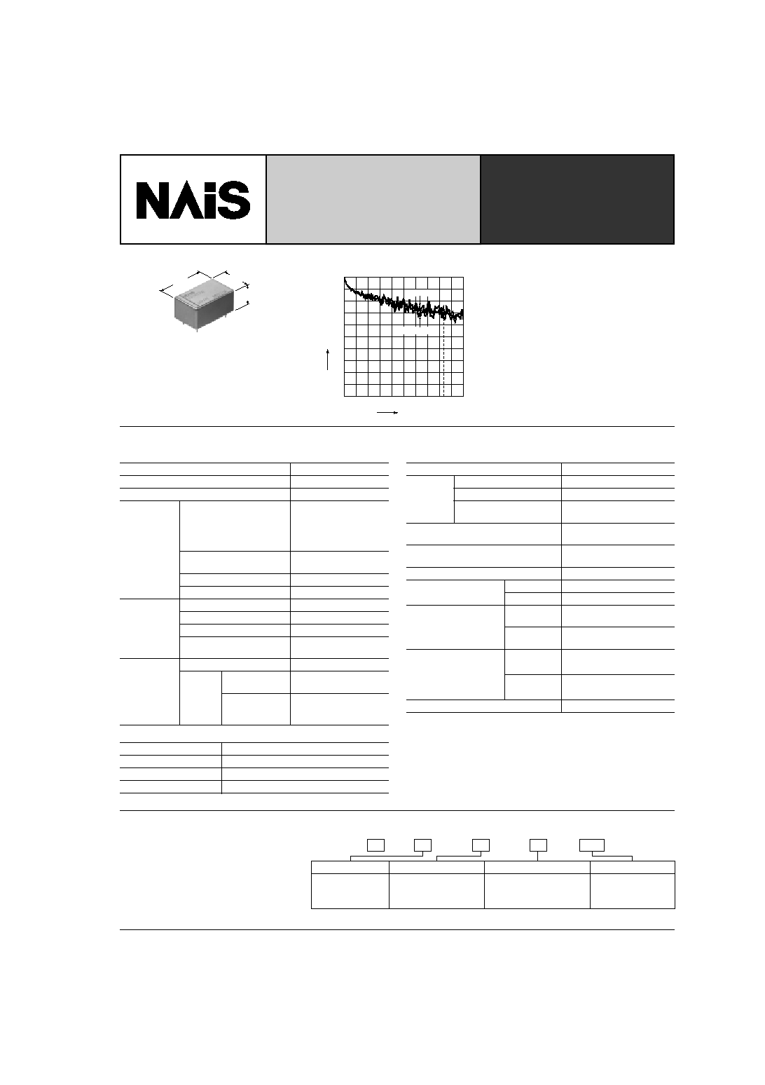
1. High frequency characteristics
Sample: ARX1012
Measuring method: Measured with HP network analyzer (HP8753C).
The details for the high freqency characteristics and the measurement
procedures and conditions are listed in the RX relay test report.
∑ V.S.W.R. (Return loss)
∑ Insertion loss
∑ Isolation
40
50
0
10
30
20
300kHz
1.5GHz
2.5GHz 3GHz
COM-NO
5.0
2.0
1.5
1.2
1.1
COM-NC
Return loss, dB
Frequency
V.S.W.R.
0.4
0.5
0
0.1
0.3
0.2
300kHz
1.5GHz
2.5GHz 3GHz
COM-NC
COM-NO
Insertion loss, dB
Frequency
80
100
0
20
60
40
300kHz
1.5GHz
2.5GHz 3GHz
COM-NC
COM-NO
Isolation, dB
Frequency
NOTES
1. Coil operating power
Pure DC current should be applied to the
coil. The wave form should be rectangular.
lf it includes ripple, the ripple factor should
be less than 5%.
However, check it with the actual circuit
since the characteristics may be slightly
different. The nominal operating voltage
should be applied to the coil for more than
30 ms to set/reset the latching type relay.
2. Coil connection
When connecting coils, refer to the wiring
diagram to prevent mis-operation or
malfunction.
3. External magnetic field
Since RX relays are highly sensitive
polarized relays, their characteristics will
be affected by a strong external magnetic
field. Avoid using the relay under that
condition.
4. Cleaning
For automatic cleaning, the boiling
method is recommended. Avoid ultrasonic
cleaning which subjects the relays to high
frequency vibrations, which may cause
the contacts to stick.
lt is recommended that a fluorinated
hydrocarbon or other alcoholic solvents
be used.
5. Soldering
The soldering shall be performed under
following condition.
Max. 260∞C
500∞F
10s
Max. 350∞C
662∞F
3s
In addition, when soldering the case to the
PC board, the plating may swell
depending on the soldering conditions.
6. Conditions for operation, transport
and storage conditions
1) Ambient temperature, humidity, and
atmospheric pressure during usage,
transport, and storage of the relay:
(1) Temperature:
≠40 to +70∞C
≠40 to +158∞F
(2) Humidity: 5 to 85% RH
(Avoid freezing and condensation.)
The humidity range varies with the
temperature. Use within the range
indicated in the graph below.
(3) Atmospheric pressure: 86 to 106 kPa
Temperature and humidity range for
usage, transport, and storage:
2) Condensation
Condensation forms when there is a
sudden change in temperature under high
temperature and high humidity conditions.
Condensation will cause deterioration of
the relay insulation.
3) Freezing
Condensation or other moisture may
freeze on the relay when the temperature
is lower than 0∞C
32∞F
. This causes
problems such as sticking of movable
parts or operational time lags.
4) Low temperature, low humidity
environments
The plastic becomes brittle if the relay is
exposed to a low temperature, low
humidity environment for long periods of
time.
Temperature,
∞
C
∞
F
85
5
0
32
70
158
≠30
≠22
(Avoid
condensation
when used at
temperatures
higher than
0
∞
C
32
∞
F
)
Humidity, %R.H.
Tolerance range
(Avoid freezing
when used at
temperatures
lower than
0
∞
C
32
∞
F
)
4/30/2003
All Rights Reserved, © Copyright Matsushita Electric Works, Ltd.
Go To Online Catalog